When you click on links to various merchants on this site and make a purchase, this can result in this site earning a commission. Affiliate programs and affiliations include, but are not limited to, the eBay Partner Network.
I'm so excited, I can finally use the trunk!
Ever since I got the car the hatch was near impossible to use. It had to be slammed really hard to latch, the electric release didn't work, and the key is broken from turning so hard. I never bothered to fix it because there was a huge subwoofer in there that took up the whole space (it came that way).
Well now it all works perfectly, electric release included.
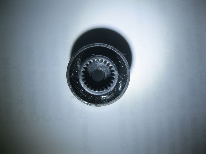
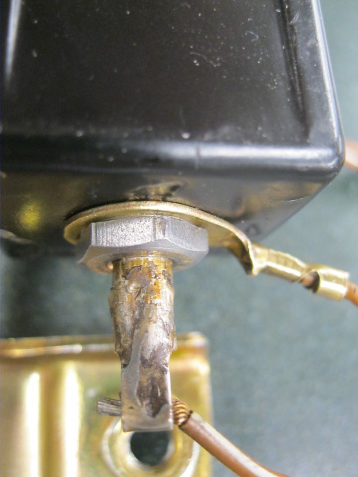
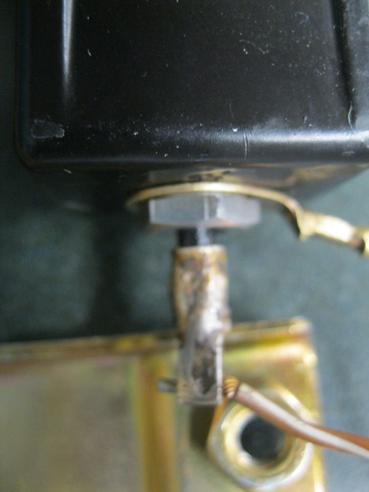
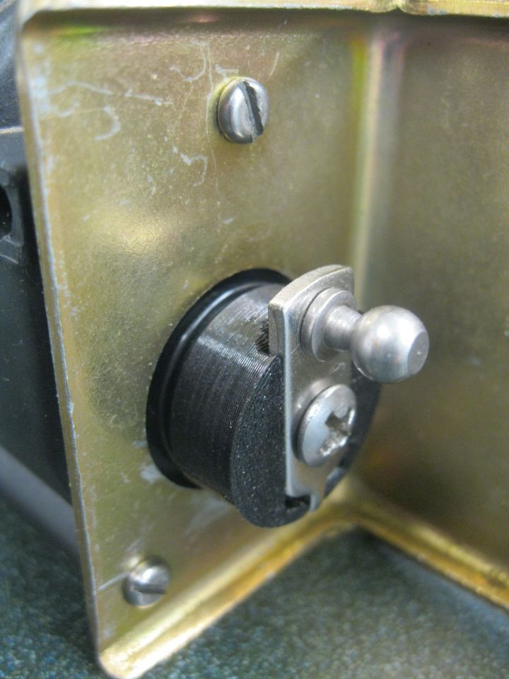
Some anti-rotation dimples and then JB Weld.
A spacer added so the JB Weld doesn't tighten against the brass bushing.
A relief notch for the zip tie that clamps the cracked housing bushing boss.
Sometimes I just don't know when to stop!
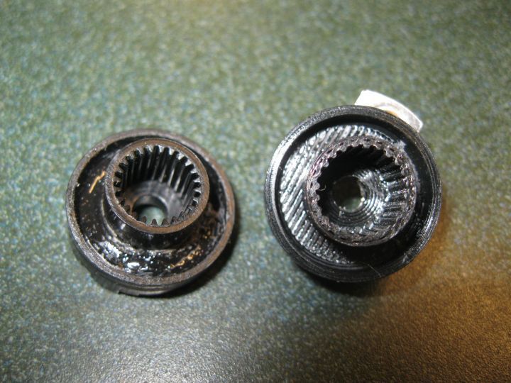
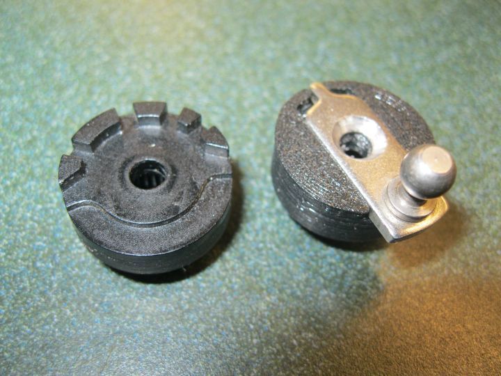
The JB Weld repair worked just fine but I couldn't resist the 3D printer calling.
So I successfully modeled and printed one.
The file is attached in case anyone wants to try.
I changed the extension to pdf because stl files can't be attached. Of course it won't open as a pdf but just save it and change extension back to stl.
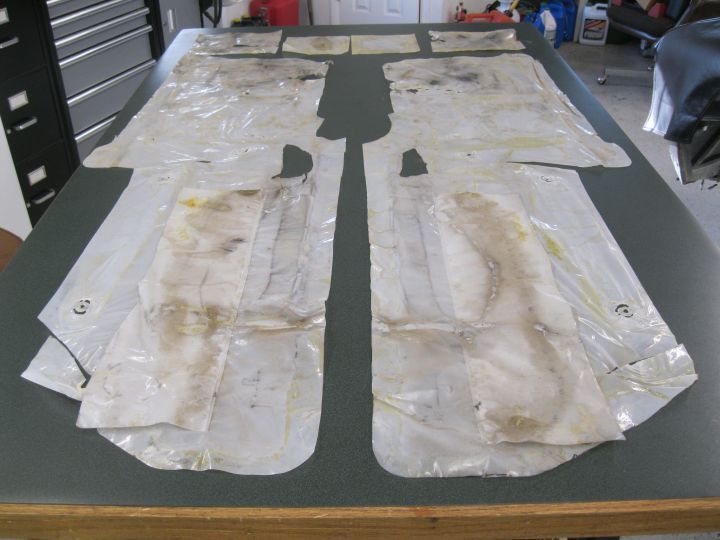
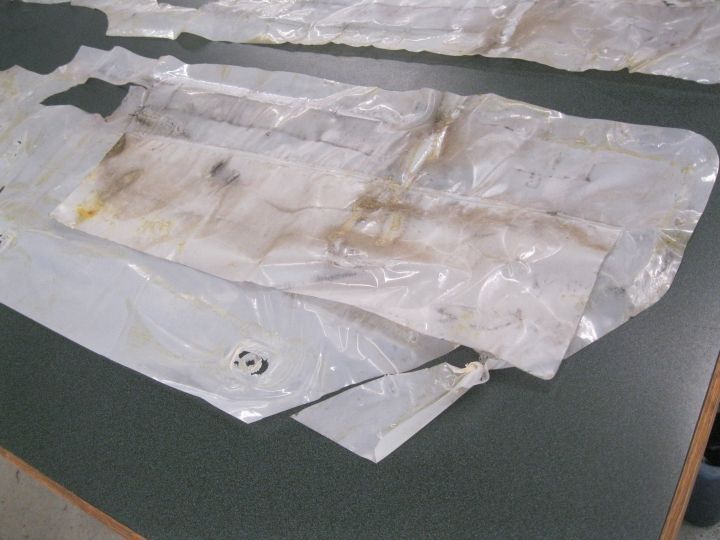
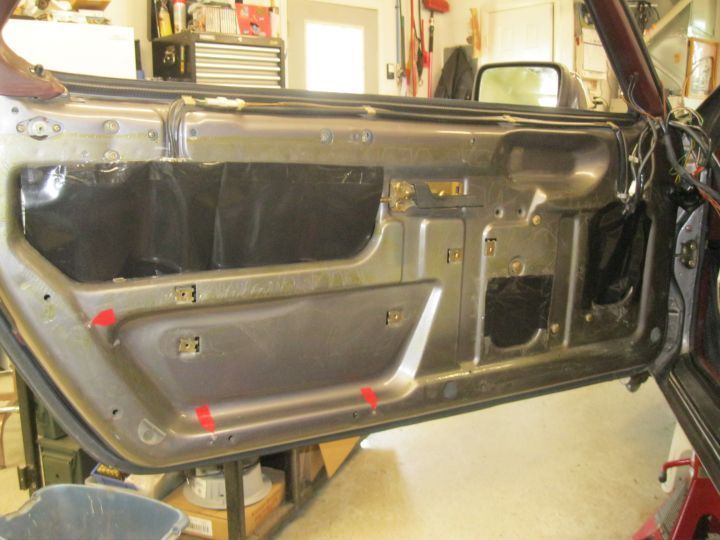
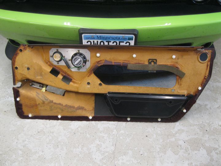
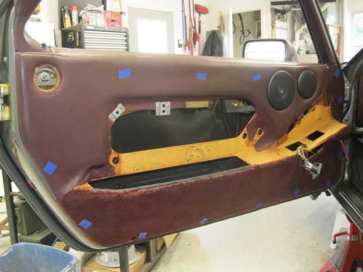
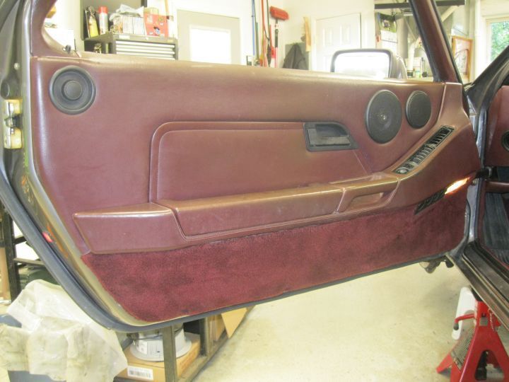
Judging by the flaps, I'd say these are original plastic pieces.
I suppose they could have gone back on but they're a little beat up and there's really no value in keeping them original.
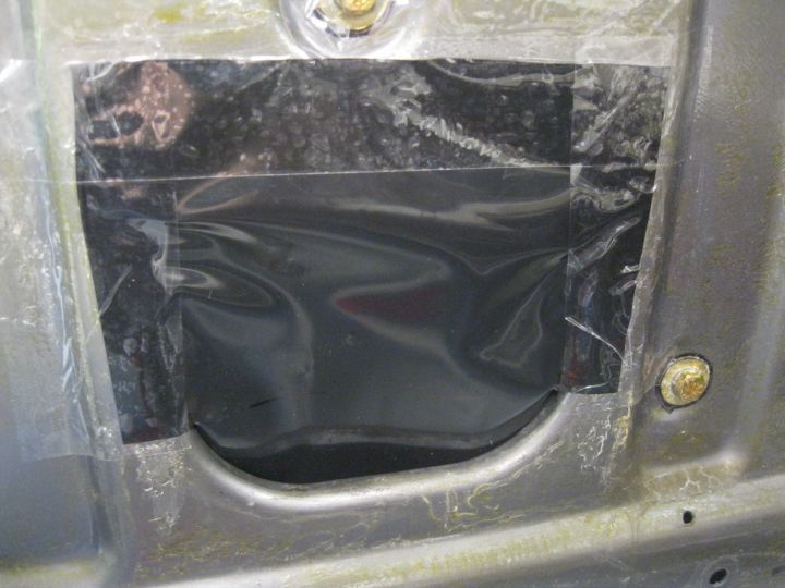
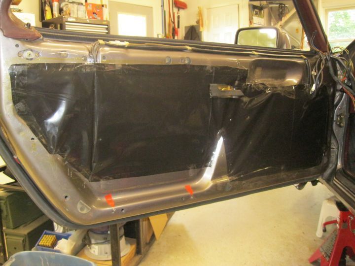
And, I just happened to have some nice 5 mill lying around, albeit not clear, but that doesn't really matter.
I have lots of different adhesives that would have worked but they're all messy so I just used shipping tape. Clean and easy to work with. I think it will be just fine.
Clips are all new and proper: 11 white, 2 black, and 2 natural for the insert cards. DS door also had three screws, PS door had none.
Or about to be dialed.
Took a good chunk of the day off. Went to see SOF at 9 am and that took all morning, then domestic chores.
But I did manage to get some 3D printing in.
Tomorrow is another day.
Started with MAF at 382 ohms and O2 volts about 0.5 with light pretty much solid but did rapid flash when switch turned on.
Video is with MAF at 260 ohms and O2 volts about 0.7. Am I good to go with that?
PS - Notice that "hollow rotating" sound? What could that be, air pump? I'm going to remove belts one at a time to try and identify source.
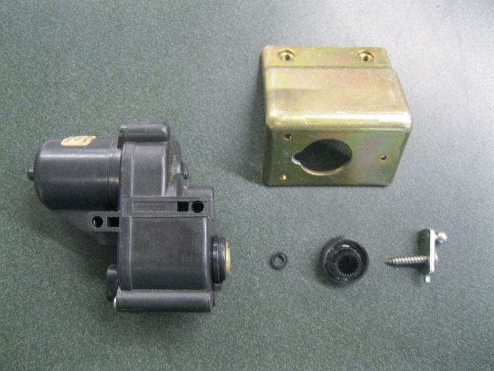
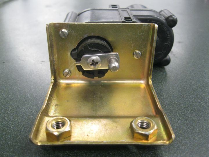
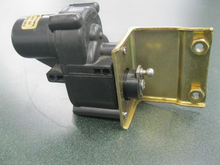
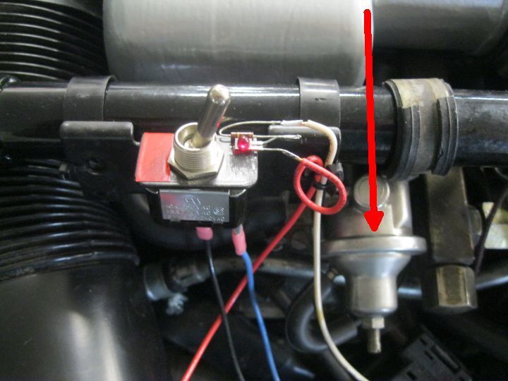
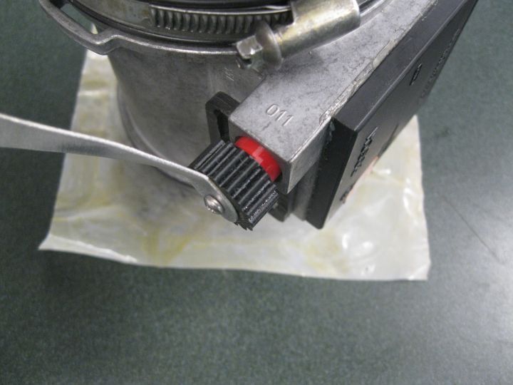
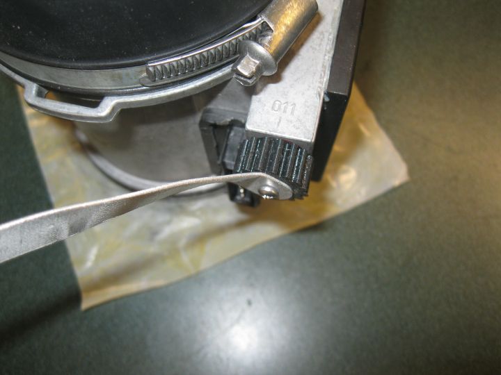
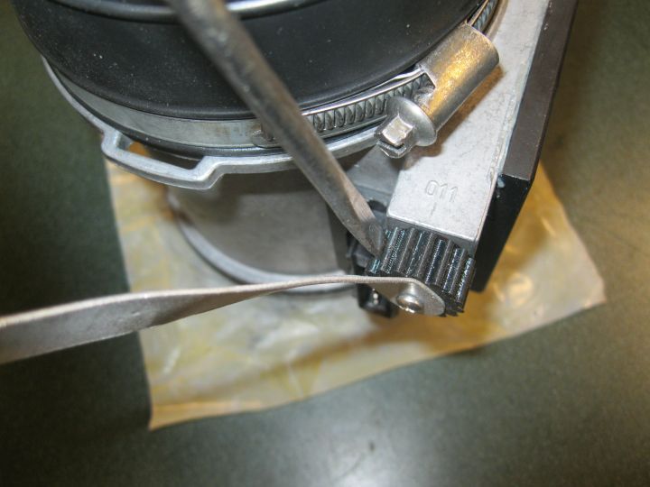
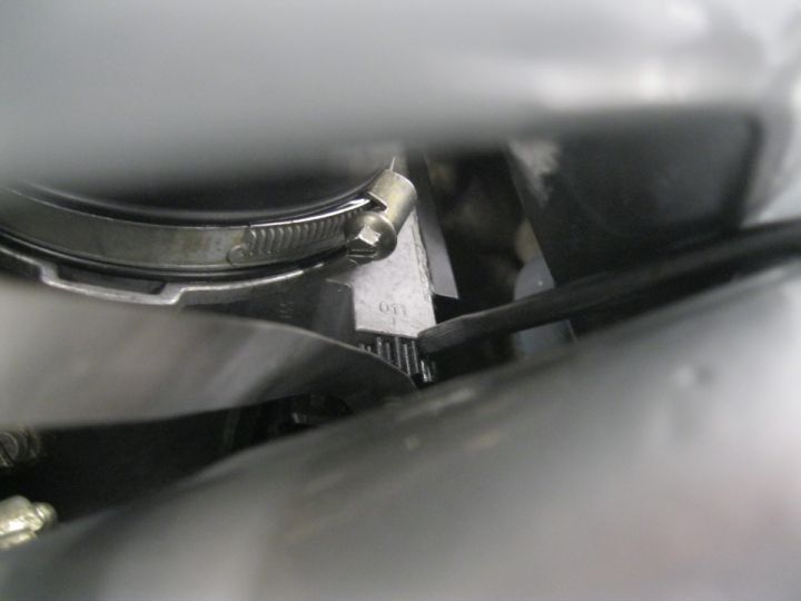
Hey Denny. That is the idle adjuster and there isn't a lock nut on it. You may have already found that out though.
So you made one of Ken's Blink'rs? I may need to hit you up for some knowledge transfer on how to make one. I read through a post on it one time but got a bit confused. I tried to set the idle on my 86.5 when I first got it back together, but started surging really badly every time I tried. I'm not sure if I had the Idle Air Stabilizer properly disabled or not.
Are those 25# injectors you're using plug-and-play? I've been considering replacing my stock ones.
-Ethan
Originally Posted by depami
Is this the idle adjuster?
Is that a lock nut that needs to loosened first?
Thanks.
Thanks Ethan, I already figured out the idle adjuster. But I didn't have to adjust it. When I rebuilt the throttle body I just counted turns and put it back where it was and it idles right at 680 (best I can tell by the dash tach). Even after adjusting the MAF, idle was still right on.
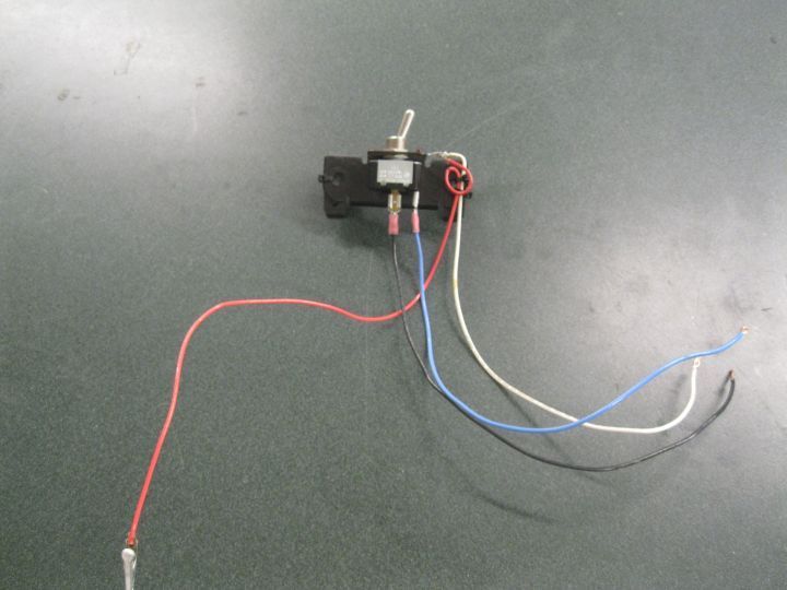
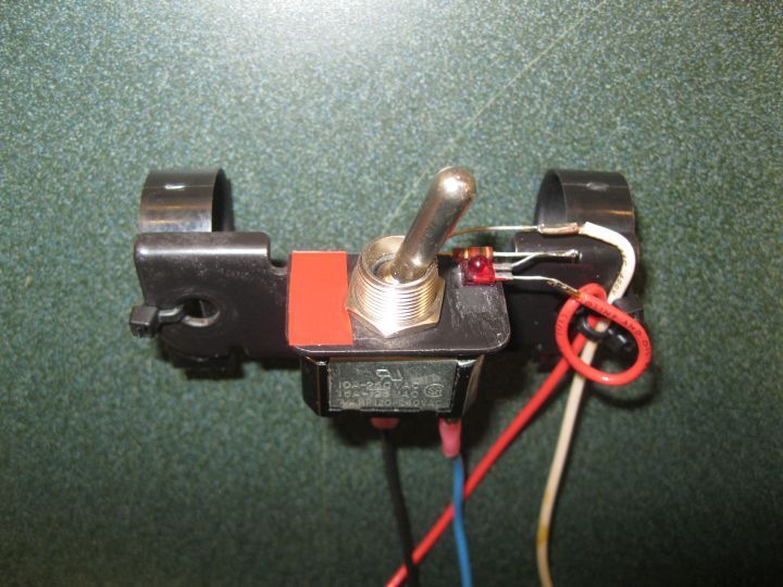
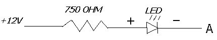
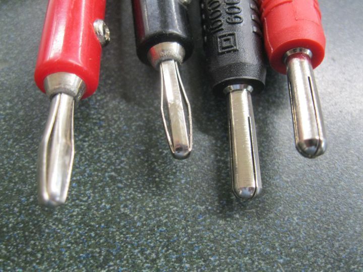
Yes I built a blinker and it's really easy. But then my secondary education is in electronics. (If you go back and look closely at my ignition wire photos you might notice that the wires and distributor caps are marked 1 through 8 using the resistor color code. When my eyes see those colors, my brain sees numbers.) The blinker is just a switch that shuts off auto idle adjust when closed and an LED that is driven by an LH output. The LED needs a series resistor to limit current, or an LED for 12v (built in resistor). One side of the LED/resistor goes to the jump post for power and the other side to the test connector pin that gets grounded by the LH. If you look closely at the images in post 169 you can follow the wires and notice that I color coded the test connector to match the wires. Most LEDs will work from 10mA to 20mA (0.010 - 0.020 Amps). Kens original post showed 750 ohm but I used 1k because that's what I had. Ohms Law E=IR where E = volts, I = amps, R = resistance (ohms). So in my case, 12 / 1000 = 0.012 or 12mA.
The 25# Bosch injectors plug right in and work. I had them in and it ran rich but I had a bad MAF. While waiting for replacement MAF I got all the original Porsche injectors to work so I put them back in. The 25# would probably be just fine with the new MAF but not sure if I'll but them back in or not. Once I finally test drive the thing, if it runs as good as it did before, I'll just leave the original ones in. In which case the Bosch 25# will be available.
Thanks Denny. That's pretty straight forward. The last time I tried to adjust the idle screw the engine started surging like crazy. I don't think I had a good connection at the diagnostic connector for disabling the idle control. I had just stuffed a wire into the b and c c sockets. I'll find some pins that fit and use a switch this time.
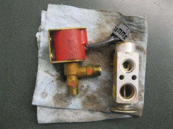
Expansion valve might be stuck. Fortunately they are only 20 bucks so both front and rear will be replaced.
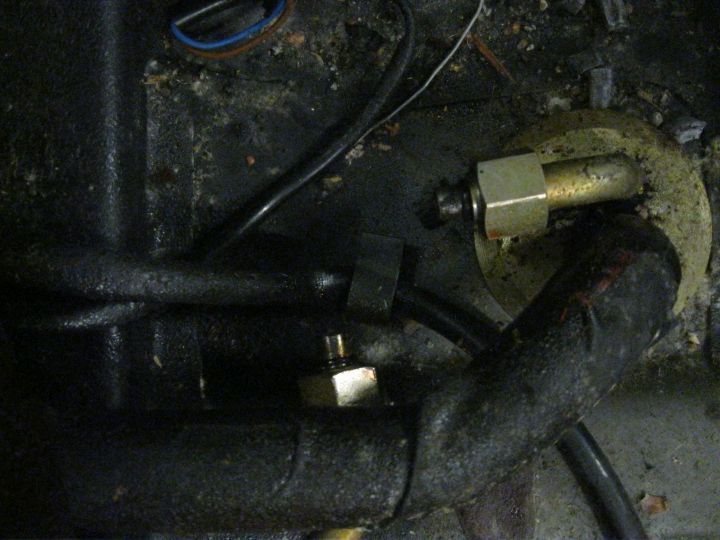
Solenoid valve was stuck too and it's over a hundred bucks but I managed to get it working properly.
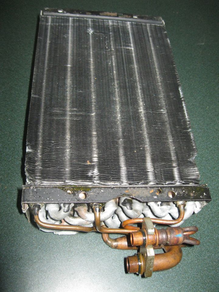
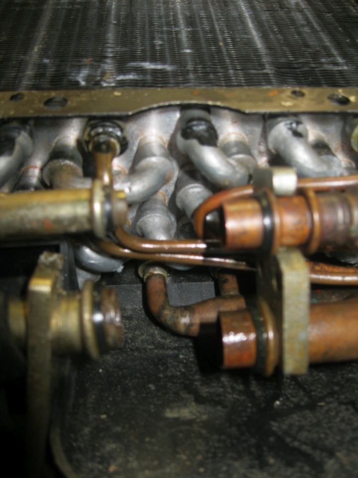
Evaporator is fine other than needing new O-rings.
How many O-rings are in the AC system? I count 29 not including compressor housing body.
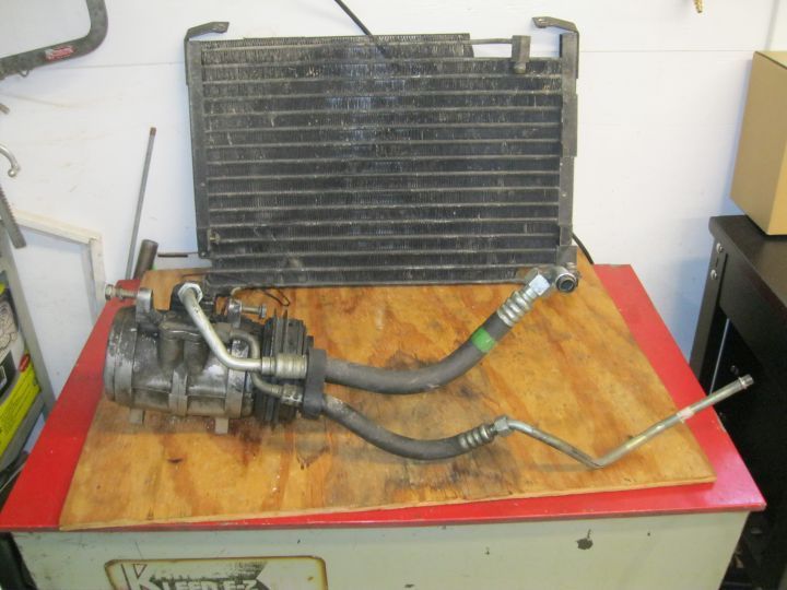
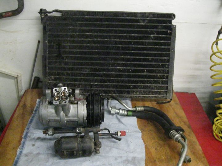
AC has been non-functional for as long as I have owned the car. Gauge connections are R134a but I have no idea what all may have been changed. I did pull a vacuum and it held over night so that's good, but I decided to go through the whole thing anyway. Some O-rings are green and some are black. Don't know what oil was in it but it was dirty so I'll flush as much as I can and then probably use Ester Oil with dye.
Rear evaporator.
Solenoid under passenger seat.
Under side view of bulkhead under passenger seat.
Saving these till after flush.
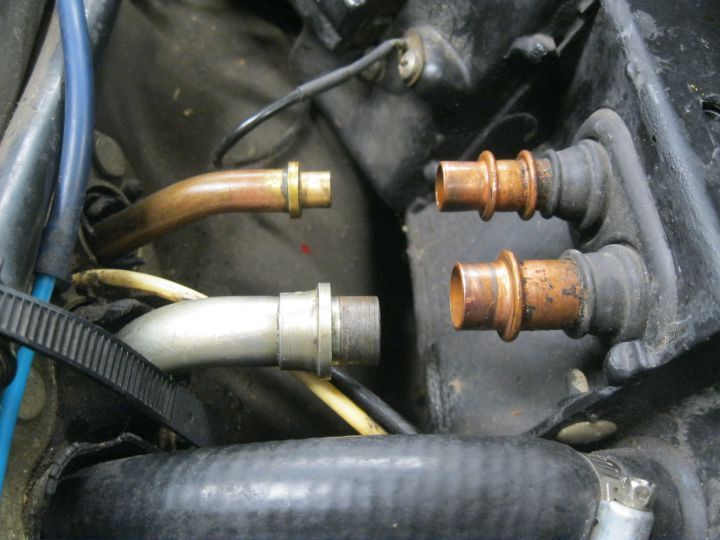
Front evaporator near wiper motor.
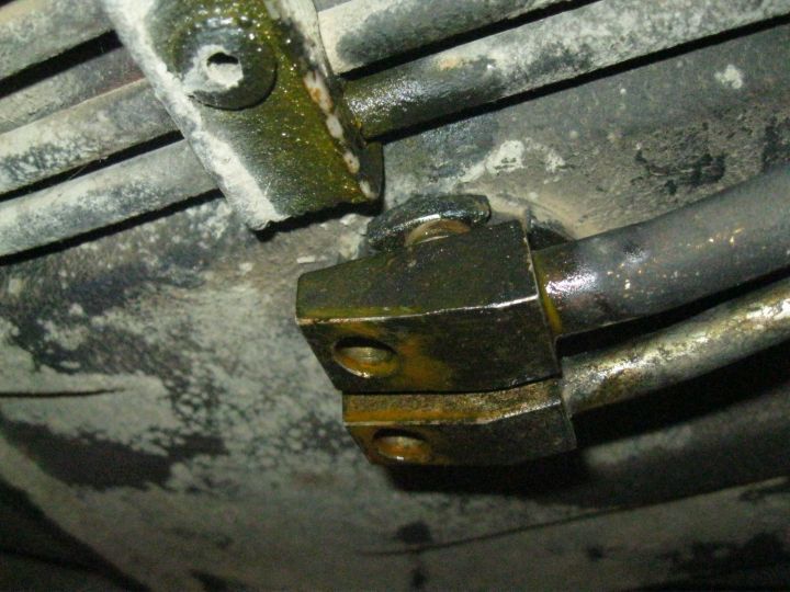
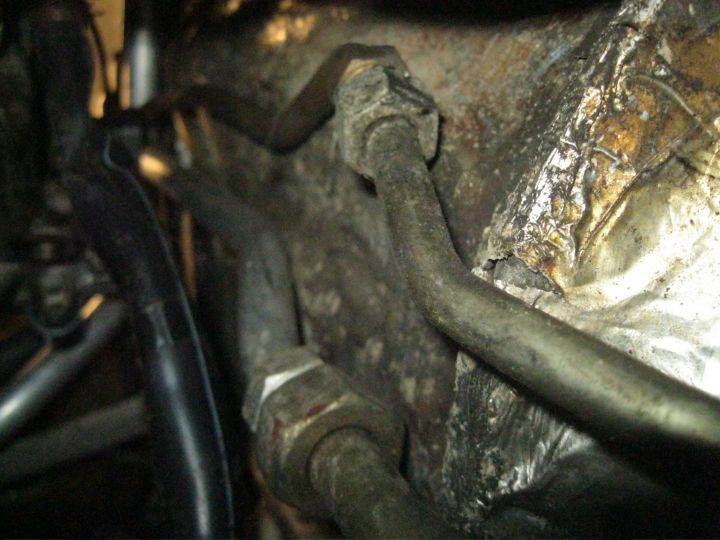
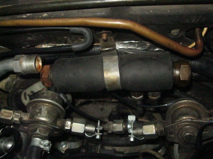
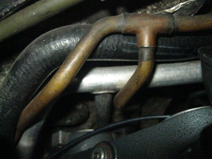
Fuel cooler on firewall.
These were fun. Should I flush fuel cooler?
Tees will make flushing a challenge. Do I even need to flush the hard lines?
I suppose Schrader valves should be changed too.
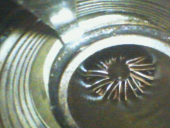
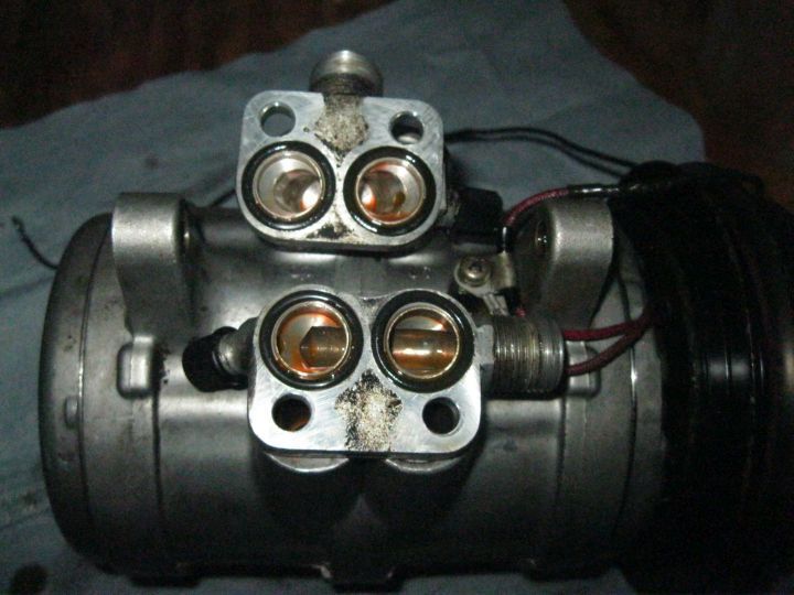
Should I split the compressor and change body and shaft seals or just leave it alone since it has good suction when turned with a drill and considering the system held vacuum?

 06-28-2023, 10:30 PM