When you click on links to various merchants on this site and make a purchase, this can result in this site earning a commission. Affiliate programs and affiliations include, but are not limited to, the eBay Partner Network.
The imbalances of my wife's checkbook and of the mid-range resonance of the S4 intake manifold are both established facts at this point.
I think we now understand exactly what the designers wanted with the S4 intake manifold and why they did what they did. It all makes sense for what they were trying to do. They did rely heavily on the knock retard function and on the catalytic converters, but that allowed them to get a pretty flat torque curve without variable valve timing.
On cam timing: Thinking about magnitudes, I just don't see the belt stretch being a factor in cam timing to the point that it could make any difference, for either version of the Gates belt. In particular, the load on the belt between cam gears is relatively low, so I don't think the belts make any difference on the relative cam timing between banks. I can't prove this, it's just my sense of the magnitudes.
The engine heating up has a meaningful impact on the relative cam timing. As the block heats up, it expands. The expansion pulls the cam gears further apart and changes the cam timing. I did the math some years ago and I was able to match Porsche's cam timing difference spec with the temperature change between cold and running engine and the Reynolds 390 thermal expansion coefficient. I don't know if I could redo the computation, probably would have to take two measurements (distance between the cam gear centers between the banks, the radius of the cam gear), google the thermal expansion coefficient for Reynolds 390 alloy, and scratch my head for a little. In any case, when I did that computation some years ago, I was able to convince myself (but not necessarily others) that the Porsche spec for the cam timing difference simply matches the thermal expansion of the block and there probably weren't any other factors that they thought were important.
That's my opinion anyway.
Make some marks on the cam gears that can be watched with a timing light. Hook up Sharktuner and run the engine with fixed ignition timing. Run the engine on a dyno and watch the marks.
You won't feel quite the same about belt stretch....
Make some marks on the cam gears that can be watched with a timing light. Hook up Sharktuner and run the engine with fixed ignition timing. Run the engine on a dyno and watch the marks. You won't feel quite the same about belt stretch....
I'll see if I can run that timing light test looking thru the cam belt cover venting hole. If it requires getting the engine running without the cam belt covers, forget about it...
Individual timing for four groups of two cylinders, yes. Knocks are recorded in 'permanent' memory in real time so the next time that (individual) engine is at that rpm, a little bit less advance is used. Eventually, all four groups will be a degree or two under their knock threshold, which should be ideal(-ish). A total of 512 cells...vs the original 16 static ones. �Qui�n es m�s macho?
I could go to per cylinder maps if I use half the rpm divisions - the limitation is in the permanent memory, there's plenty of EPROM space in the EZK for static, base maps...hmmm, I could make eight x 64 cell base maps and have eight x 32 cell learned maps...V2.0...
Timing advance tries to optimize the burn rate of the fuel/air mix. If there is more of the mix or better swirl (et cetera, et cetera) there is less need for advance as the mix will burn at a faster rate. The valleys above are hopefully where the best conditions for combustion occur. The peaks aren't terrible though, if you can put in enough advance to burn as much as possible before the exhaust valve opens. (As a side benefit, it is quieter, too.)
No spacer(s) yet. It would be nice if a spacer will let the left side pack more mix in through the mid-range. The ~24� difference in timing at ~4000 above is a little embarrassing for the S4 manifold?
Gone are the days where I hoped it would take another 2� advance at the top end to squeak out another 10 hp. There is a ~10� difference on those maps at 5850...I think it may do well on the dyno.
Ken,
You have restored some faith in my tired old mind. Trying to interpolate your chart I took a look at my current ST2 based mapping on the basis of following the lower side of the curves you plot and found some similar trends for the high load cells so perhaps I am not too far off optimal advance settings [as can be expected with simplistic batch firing] after all.
Perhaps I should put in some more advance across the board to test when cells other than No6 & No2 [my knock event leaders] start to knock. I have seen pings on other cells but they seem more random.
I look forward to reading what you find when the spacer[s] is fitted. It will be interesting to see whether the gap closes at all. If nothing else you will [I suspect] prove whether the believers [like myself] or neah sayers are right about the plenum spacers.
All kudos to you my friend and many thanks for sharing your findings to date- a truly fascinating insight into just what may be going on here for those of us that feel something is happening but no real idea what.
Best wishes to all for Xmas/New Year.
Regards
Fred [probably working]
A heat range or two colder spark plug in #2 and #6 does wonders....because even once you "cure" the intake manifold problem, those cylinders run hotter, simply because of water flow.
You have restored some faith in my tired old mind. Trying to interpolate your chart I took a look at my current ST2 based mapping on the basis of following the lower side of the curves you plot and found some similar trends for the high load cells so perhaps I am not too far off optimal advance settings [as can be expected with simplistic batch firing] after all.
Perhaps I should put in some more advance across the board to test when cells other than No6 & No2 [my knock event leaders] start to knock. I have seen pings on other cells but they seem more random.
Sometimes it seems you can never get rid of the knocks. Some places won't show up until the right conditions are met. Some are rare because the EZK knock retard covers them up. If there is a knock that you can't adjust out early in a WOT pass you may never see where it knocks higher up. (I've had to adjust the factory retard programming somewhat so that I can get a proper record.)
You can see the erosion over time below as the 4/7 group races to the bottom. It's so refreshing now that the lower the valleys get, the faster the car goes.
It will be interesting to see what it will look like if at some point I drink enough coffee to make per cylinder maps...and log another 1000 WOT runs to make the base maps...and...therein lies madness, heh, heh.
A heat range or two colder spark plug in #2 and #6 does wonders....because even once you "cure" the intake manifold problem, those cylinders run hotter, simply because of water flow.
Greg,
That is an interesting suggestion. I use the stock WRD7 or whatever it is with the copper conductor [I understand this plug type gives a relatively wider heat range but no clue as to the reality of such]. Presumably a colder plug would be a WRD8 [assuming it goes that way].
Do you see any signs of carbon or experience other debits using the colder plugs [all cylinders?] or do you rely on "giving it some clog" to ensure you get any carbon to burn off?
No problems, Fred. Maybe a touch of idle roughness for a few seconds after startup in very cold weather. I check the gap weekly when I'm doing a lot of logging runs and they are always clean.
Received the spacers today. Thank you, Greg.
Forgot that the fuel rail has to come off to install the spacer. That will be interesting on the dyno, although, if the advance level doesn't change with the spacer on the left side, I probably won't bother.
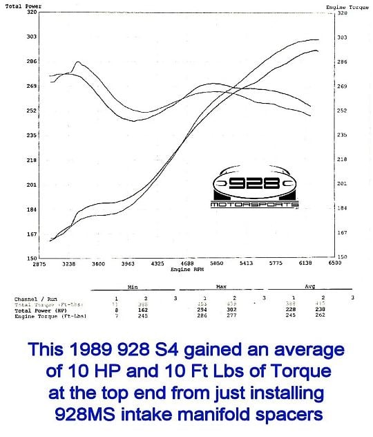
I'd thought about using spacers to give more breathing space around the intake bellmouths, but then saw the dyno results with the spacers from 928 Motorsports.
Could not understand the loss in low end torque. If the plenum resonance now occurred at a lower frequency (larger volume) surely that would just move the torque peak, not reduce it?
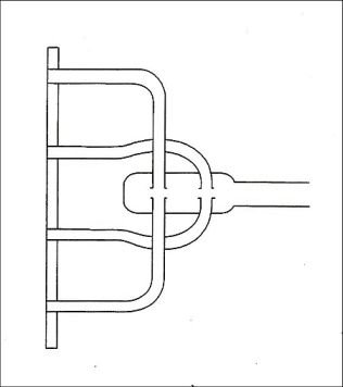
Manifold pulse reinforcement:
Underlying principle: intake bellmouth placement matches the firing order such that the 'closing intake reflects a +ve pressure wave that returns to its bellmouth in time to reinforce the induction wave on the other cylinder. Bellmouth separation not greater than 0.75 tract diameter. Lost the URL in a disk failure.
When this concept is applied to the firing order of the cylinders whose bellmouths appear in the L & R plenums, the low speed resonance mechanism becomes clear.
Also, the loss of low speed torque 'with spacers' is explained: while at first glance the close proximity of the side covers over the intakes appears to shroud the airflow around the intake bellmouths, it otherwise improves the 'pressure wave' coupling between the bellmouths, which is what produces the low-end torque.
The use of 'spacers' has two effects:
- it decreases the pressure wave coupling (loss of low speed torque), but -
- it un-shrouds the bellmouths and allows better high rpm breathing.
Dyno results with 'spacers':
UpFixenDerPorsche.
'90 GT
'89 S4
'03 BMW R1100S
Last edited by UpFixenDerPorsche; 12-25-2014 at 06:47 AM.
In my opinion, that dyno graph is not replicable. Something else was going on with the car as it was tested, which is evident from the stock baseline curve. A lot people have tested these spacers and as far as I can tell, nobody has gotten results like that 928MS dyno graph with a stock or near stock car.
Here's what I think. This is not a fact, it's an opinion. Your mileage will vary if you choose believe me:
Without changing the stock LH/EZK calibration in any way, adding the spacers will
(1) move the first flappy-closed torque peak to a slightly lower rpm. This is because in the dual independent resonator mode, an increase in plenum volume will move the resonant rpm down.
(2) shift the optimal flappy open point to a slightly lower rpm, for the same reasons as above.
(3) since the programmed flappy opening point doesn't change with the addition of spacers, the spacers create a slight dip in the torque curve before the flappy opening point and there will be a slight but discrete step up when the flappy opens
(4) possibly a very small positive effect in the mid range rpm (when the flappy is open) but not large enough to measure on a dyno. This is due to slight unshrouding of some of the intake bellmouths. The unshrouding is very slight, unless the spacers are permanently attached to the manifold and then the manifold ported to maximize the unshrouding allowed by the spacer.
(5) possibly a very small negative effect at high rpms (when the flappy is again closed) but not a large enough to measure on a dyno. This is because the spacers again move the Helmholtz resonance peak to lower rpms, shifting the flappy closed torque curve to lower rpms which will very slightly hurt the high rpm cylinder filling.
I am not against using spacers, in fact I think they are very useful if one wants to accomplish what they actually accomplish. I am only against using these kinds of spacers under the false understanding of what they'll do and then ending up disappointed.
[SIZE="2"]
I'd thought about using spacers to give more breathing space around the intake bellmouths, but then saw the dyno results with the spacers from 928 Motorsports.
Could not understand the loss in low end torque. If the plenum resonance now occurred at a lower frequency (larger volume) surely that would just move the torque peak, not reduce it?

 12-23-2014, 07:29 PM