When you click on links to various merchants on this site and make a purchase, this can result in this site earning a commission. Affiliate programs and affiliations include, but are not limited to, the eBay Partner Network.
I'm accumulating all of the LED's for my brother's 89 digital dash upgrade according to your guide and have discovered that the B8.4D LED's don't seem to be available anymore. Will B8.4D HP's work in their place or will they be too bright?
Thanks,
Duncan
They'll probably be just fine. When you get done, though, please report back and share your findings.
This morning, I took a photo of a Super Bright LEDs B8.4D-R (left) and a B8.4D-RHP (right). The HP throws more light and it has a more uniform pattern.
Oh... and if you're the same Duncan from Melbourne that ordered a couple of AILD-1s the day before yesterday, they shipped that same day.
They'll probably be just fine. When you get done, though, please report back and share your findings.
This morning, I took a photo of a Super Bright LEDs B8.4D-R (left) and a B8.4D-RHP (right). The HP throws more light and it has a more uniform pattern.
I just installed the HP bulbs yesterday. They're quite bright, but I can't say firsthand how much brighter they are than the other LEDs you used in your guide as I don't have them for comparison. Your pic seems to show a significant difference though. Definitely much brighter and more vivid than the incandescent bulbs, and that is all that matters to me.
One thing I can say is that you don't have to modify the board at all to make them fit--they go in perfectly with no modifications needed.
I just ordered up one of your dimmers as well so that I can dim the lights if I find them too bright. Looking forward to the spring so that I can test it out in the wild!
I just ordered up one of your dimmers as well so that I can dim the lights if I find them too bright. Looking forward to testing it out in the wild!
And I'm just preparing yours for shipment right now (and as it's after 5 PM here, so we're into happy hour, making it a more enjoyable task... )
Note that the rheostat-controlled dimmer will dim the main cluster (back)lighting, but not any of the warning/indicator instrument bulbs in the cluster.
Hi there,
This solution looks perfect however I have a 1995 968 and not sure if this would work.
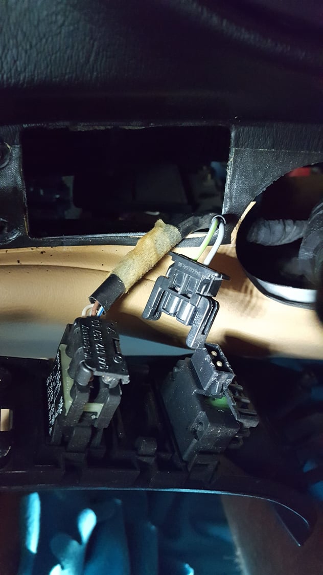
[image removed]
You can see the connector there for what hooks into the back of the dimmer.
Ill be honest, not much of an electrician so some of these topics I don't fully understand. This AILD-1 looks amazing if it would work...
Thanks for any help. Ill post specifically to the 968 forums also.
It should work. That potentiometer/rheostat looks almost identical to the one in the 928. It has a different Porsche part number (944.613.131.00, vs. 928.613.031.00 70 for a 928 '89+), and OEM number (04 8016 00, vs. 04 8016 01 for a 928 '89+); the only difference I note is the white label on the 964's rheostat. It might be a different resistance, though. If it's a significantly different resistance, you could just train the AILD-1 using your rheostat.
If you do want to give it a try, you'd probably want to get one of the "AILD-1 connection kit for '90-'95 Porsche 928" options (either the one for soldering or crimping, whatever you'd prefer). Or just get a connector ("Ready-to-wire, labeled plug for AILD-1; no wires provided") and supply your own wires (since I don't stock the colors that would exactly match your 968; they're different than the ones for the 928); I could help you select properly-matched wires from Eagle Day (1.0 mm2 thinwall (TXL) automotive wire).
It would help to get electrical diagrams for the '95 968, too, so I could see which rheostat wire is input and which is output. I could also help you determine that if you have a multimeter (or even some kind of 12 V test light) available.
Thanks for the response! Sorry for delay in getting back.
I am fine with trying the AILD-1 kit if we think we'll have success. I love the LED look however the glare is not ideal. Is there somethings I can do to verify that this will work before purchasing? Given it is for 928s, obviously happy to poke around here for whatever we need to confirm.
1. Wiring kit- Ill go with the crimping likely. This would mean I wouldn't need any additional wires I assume?
2. Electrical diagram for the 968 is so far impossible to come by. I have ask some Porsche guys here and same result, ie: nothing out there. 944 wiring diagrams do exist however it does seem there was some changes from 944 to 968 in this specific area so not sure how much use that would be.
I do have a 12v battery that I used for testing when I installed the LEDs on the workbench. I do have a multi meter also so I can test whatever we need.
Thanks for the response Ed!
Have you soldered before? Since you're already showing a disconnected rheostat connector, you're really close to just being able to open up that connector, pull out the terminals, de-solder them, and solder new wires (the ones in an AILD-1 connection kit) to them, and then solder some of the other wires to the wires you de-soldered from the rheostat.
Otherwise, you cut those wires (leaving enough to work with) leading to the rheostat connector and then crimp on terminals and then use the AILD-1 connection kit that has wires that terminate in compatible terminals.
It sounds like we need to figure out a couple of things, both which can be done with your multi-meter.
Determining the resistance of the rheostat. With the rheostat disconnected and the multimeter set on ohms/resistance, measure the resistance from one rheostat pin to the other. First, with the rheostat wheel rolled all the way to one end. Then, with the rheostat wheel rolled all the way to the other end. You should get almost a direct short (something close to 0 Ω) at one end and something less than 10 ohms (I'd guess 5 or 6 Ω) at the other end. On a 928, it's somewhere in the 5 Ω to 6 Ω range.
Determining which of the two wires leading to the rheostat is the input (the source current from the light switch/fuse/relay/whatever) and which is the output (connected to the various instrument lights). With the rheostat disconnected and the multimeter set on DC volts, turn on the parking lights (whatever you'd do that would energize the instrument lighting). Put the black lead of the multimeter on a chassis ground somewhere (some bare metal that you're pretty sure is a good electrical ground for the vehicle). With the red lead, probe each of the two pins in the connector that goes to the rheostat. One should read something close to 0 V (this will correspond to the rheostat output), and the other should read something close to 12 V (this will correspond to the rheostat input). Record the wire color codes for output (what showed as 0 V) and input (what showed as 12 V). It might also be a good idea to clean your rheostat before doing these tests, as these rheostats are known to be temperamental, going "high resistance" due to grime or corrosion on the wiper, resistance coil, and/or the other points (e.g., wave washer at the wheel pivot point) in the electrical path.
Armed with that information, I'll be able to confirm that the AILD-1 will work for you (I'm already about 90% sure ) and give you exact instructions on how to hook it up.
Last edited by Ed Scherer; 10-06-2017 at 02:46 PM.
Ed,
This post is awesome, thank you. I need a bit more time to get my act together to dismantle the dash again. I suspect end of October maybe November. Based on your description there this looks like a good option. I REALLY appreciate you help. I will aim to order the AILD1 end of this month when done with track days. Canadian Thanksgiving this weekend so this weekend is a bust .
I think you're right, soldering method sounds easier. I haven't soldered since high school but I am sure i could learn.
More to come Ed...
I've been sold out on these for quite a while. I'll try to get a new batch made within the next few weeks and will notify you when they're available again.

 01-07-2017, 05:50 PM


 .
. 