
PWM dimmer for instrument backlighting after upgrading to LEDs

 09-27-2013, 11:53 PM
#182
Addict
Rennlist Member
Rennlist Member
Thread Starter
FYI, assembled units are available again (14 available at the moment).
I haven't gotten much feedback on installed units yet: how's everything going with those of you who got the first 20 units? Well... 19, I guess, since S/N #1 is in my car . (Thanks, Sean and Bruce, for your feedback; I appreciate it.)
I also just shipped the first "DIY kit" version today (thanks for being an early adopter of the DIY kit, Arnoud). Still trying to figure out how to produce these things�whether pre-assembled or as a DIY kit�without burning a ton of time on it.

I haven't gotten much feedback on installed units yet: how's everything going with those of you who got the first 20 units? Well... 19, I guess, since S/N #1 is in my car
. (Thanks, Sean and Bruce, for your feedback; I appreciate it.)I also just shipped the first "DIY kit" version today (thanks for being an early adopter of the DIY kit, Arnoud). Still trying to figure out how to produce these things�whether pre-assembled or as a DIY kit�without burning a ton of time on it.
 10-19-2013, 04:43 PM
#183
Rennlist Member
Although I assembled it all on Saturday night 5th October 2013, family + work related items have stopped me from posting this thus far on Rennlist (I did informed Ed already).
Pre-preparations:
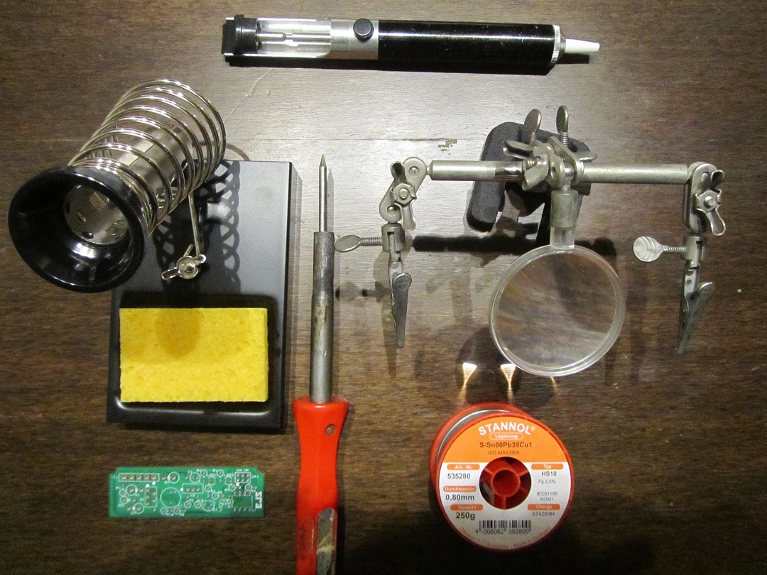
- I put everything on a working table, and only used simple tools being mostly my trusty 35+ year old 25 watt Weller soldering iron.
- For this occasion I bought a brand new small soldering tip (which I can recommend for this type of job's) + new lead-free soldering tin (S-Sn60Pb39Cu1 of 0.8mm diameter).
- Not shown but also used was:
--> a bit of sticky tape (guess what: yep, I used duck tape ), so to hold a few components up while soldering - like for example the 8-pin dil IC-socket.
--> a small wire cutter.
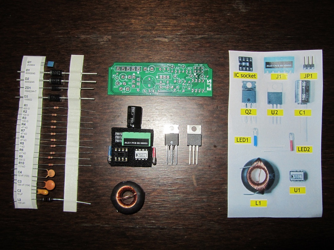
- Ed packed the electronic components in such easy to use friendly way: a total delight! If Ed did this in a manual way it must have taken him some time to place them all as precise and straight as he did!
Assembly experiences:
- Very simple and straight forward, given Ed's provided very detailed instructions manual, including the described assembly order being spot on.
- As I worked super slow, because I pre-checked and measured almost each component, it took me about 90 minutes in total to solder all components. Would I have to do another second or third one, I guess it would take me about 20 minutes from start to finish.
- In case someone would be an absolute beginner in soldering a PCB: do note that the larger diodes do take longer to get the solder flowing, so don't worry about the more time and therefore heat applied for those: all will be fine.
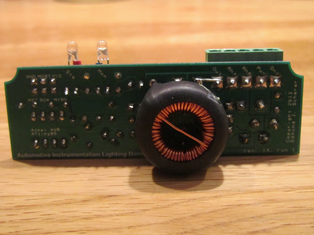
- For those that wonder in underneath photo why there is a bridge on "Out", I'll let Ed explain it in his own words as he did to me: " ...the need for that “bridge” by D2 to J1. It’s because there was (due to a bug in the PCB software when it generates the output Gerber files) an inadequate thermal relief for the J1 “Out” pad (if you look real carefully at a high-res image of the bottom side of the PCB, you’ll only see one little trace emerging from the pad to the copper pour area instead of the intended three). That’ll be fixed in rev. 1B. It will probably work even without the bridge, but I didn’t want to take any chances. ".
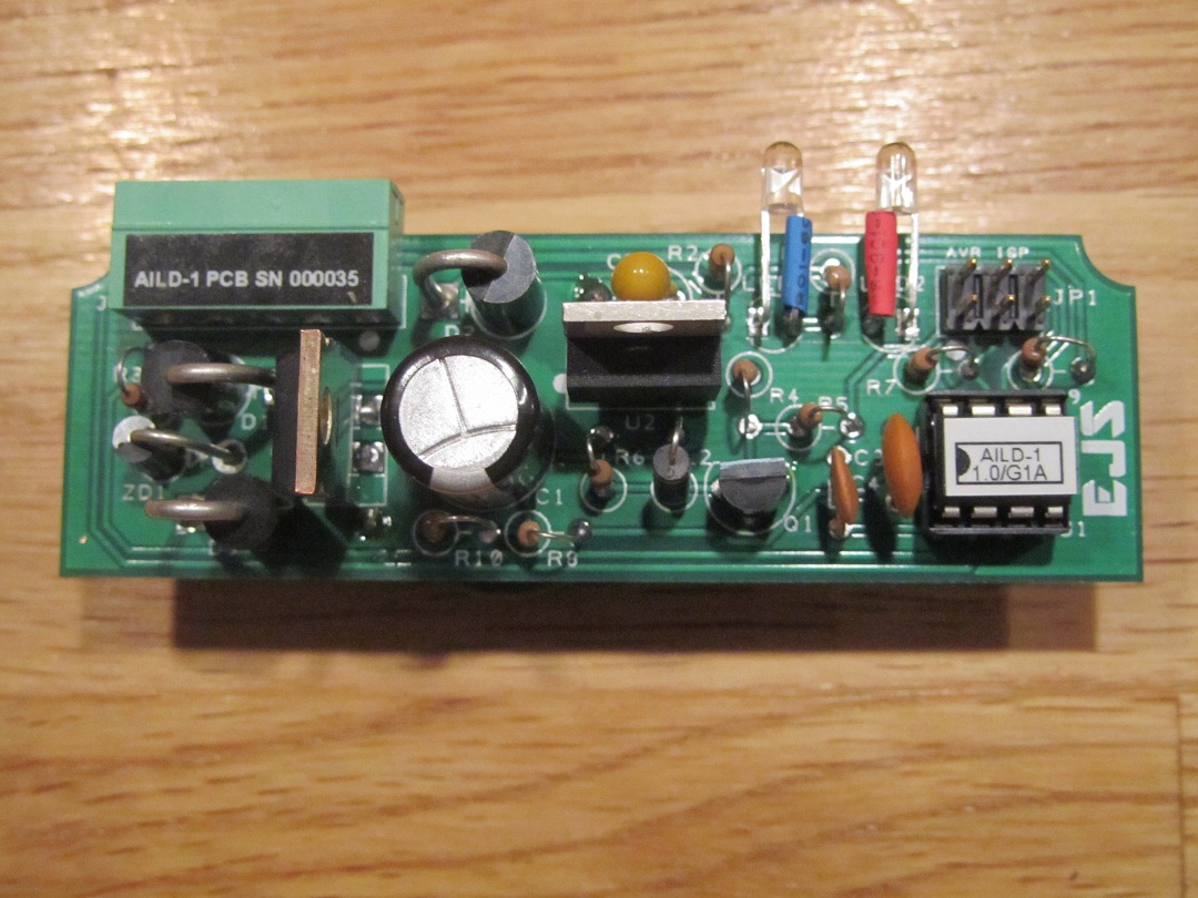
- Note that I lined up the LED's exactly as per Ed's provided very detailed instructions manual.
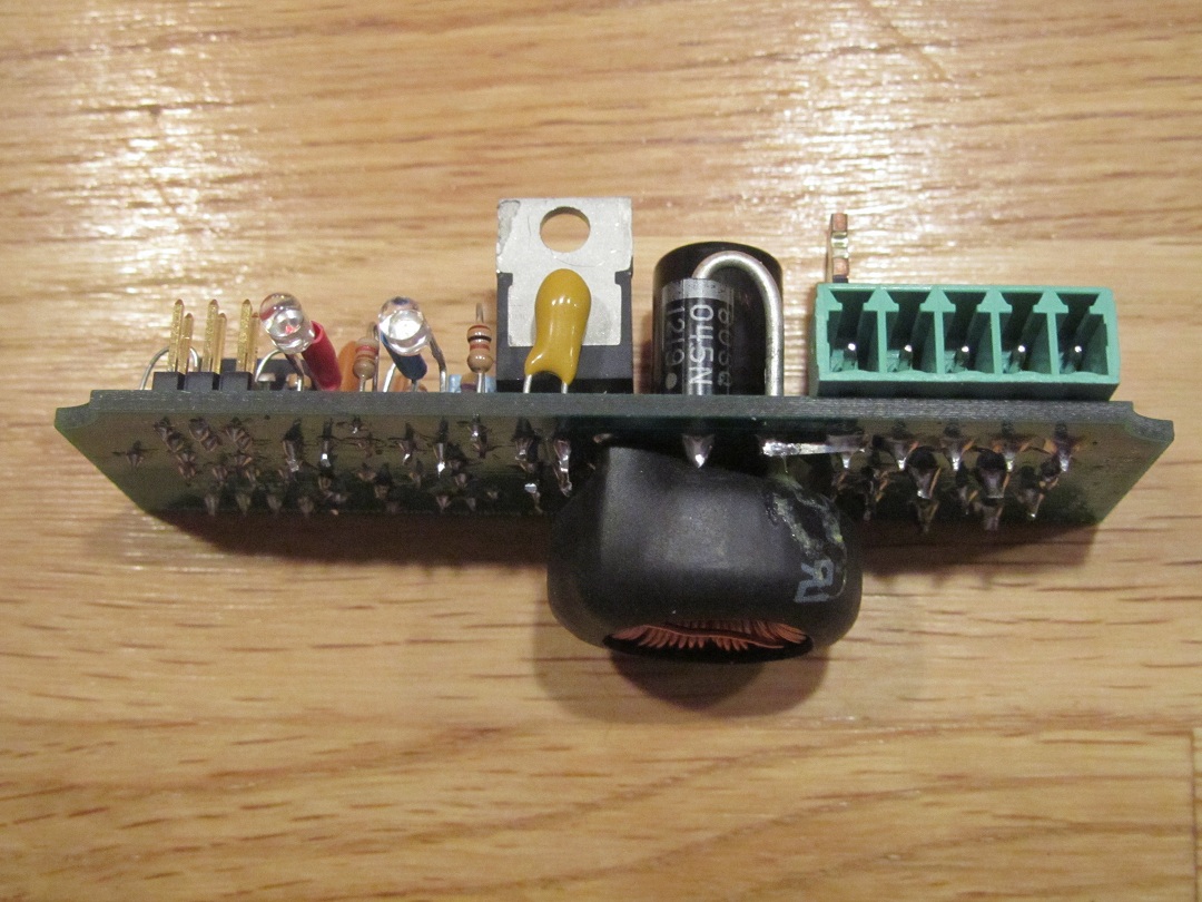
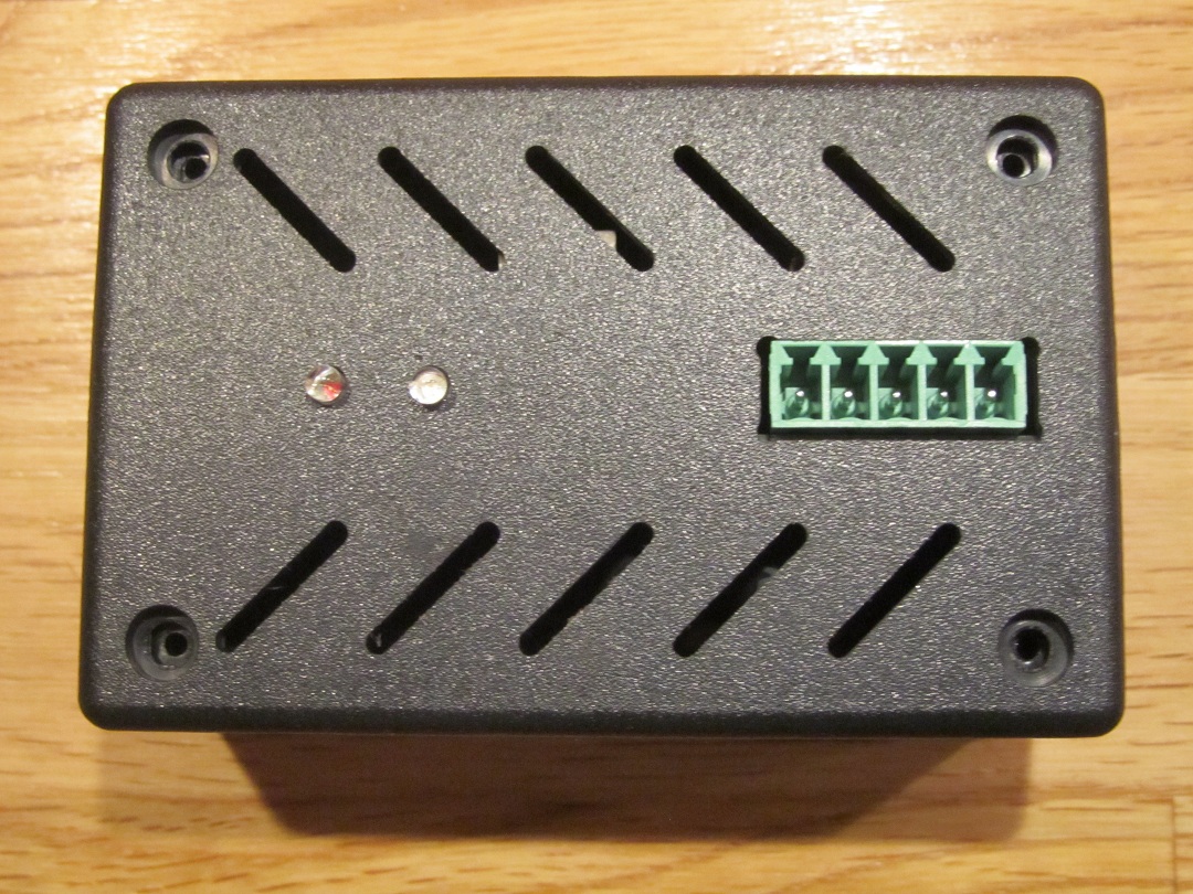
- Fit and finish of the PCB + components into the provided plastic case is exemplary: a perfect "snug" fit.
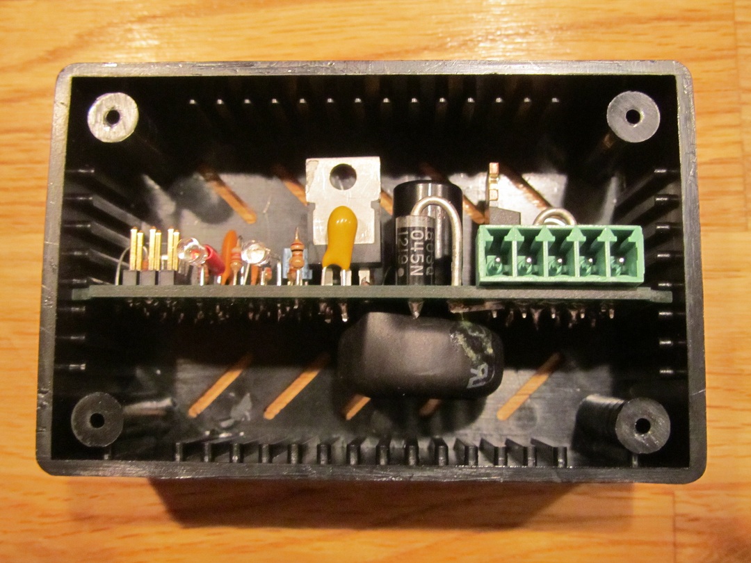
- And guess what: also a perfect line-up of the LED's and the connector @ 1st attempt of putting the lid/top on:
Initial testing:
-Initial test with a standard 12V / 15W car light bulb showed correct working: fade in at start up and dimming between 0 - ~10 ohm with an attached external potentiometer, with the blue indicator LED working accordingly.
My verdict:
- A total professional DIY electronic kit with top-notch very detailed provided installation instructions, idiot proof.
- Sold for a far too low price given all the work that Ed's must have put into this!

Pre-preparations:
- I put everything on a working table, and only used simple tools being mostly my trusty 35+ year old 25 watt Weller soldering iron.
- For this occasion I bought a brand new small soldering tip (which I can recommend for this type of job's) + new lead-free soldering tin (S-Sn60Pb39Cu1 of 0.8mm diameter).
- Not shown but also used was:
--> a bit of sticky tape (guess what: yep, I used duck tape
), so to hold a few components up while soldering - like for example the 8-pin dil IC-socket.--> a small wire cutter.
- Ed packed the electronic components in such easy to use friendly way: a total delight! If Ed did this in a manual way it must have taken him some time to place them all as precise and straight as he did!
Assembly experiences:
- Very simple and straight forward, given Ed's provided very detailed instructions manual, including the described assembly order being spot on.
- As I worked super slow, because I pre-checked and measured almost each component, it took me about 90 minutes in total to solder all components. Would I have to do another second or third one, I guess it would take me about 20 minutes from start to finish.
- In case someone would be an absolute beginner in soldering a PCB: do note that the larger diodes do take longer to get the solder flowing, so don't worry about the more time and therefore heat applied for those: all will be fine.
- For those that wonder in underneath photo why there is a bridge on "Out", I'll let Ed explain it in his own words as he did to me: " ...the need for that “bridge” by D2 to J1. It’s because there was (due to a bug in the PCB software when it generates the output Gerber files) an inadequate thermal relief for the J1 “Out” pad (if you look real carefully at a high-res image of the bottom side of the PCB, you’ll only see one little trace emerging from the pad to the copper pour area instead of the intended three). That’ll be fixed in rev. 1B. It will probably work even without the bridge, but I didn’t want to take any chances. ".
- Note that I lined up the LED's exactly as per Ed's provided very detailed instructions manual.
- Fit and finish of the PCB + components into the provided plastic case is exemplary: a perfect "snug" fit.
- And guess what: also a perfect line-up of the LED's and the connector @ 1st attempt of putting the lid/top on:
Initial testing:
-Initial test with a standard 12V / 15W car light bulb showed correct working: fade in at start up and dimming between 0 - ~10 ohm with an attached external potentiometer, with the blue indicator LED working accordingly.
My verdict:
- A total professional DIY electronic kit with top-notch very detailed provided installation instructions, idiot proof.
- Sold for a far too low price given all the work that Ed's must have put into this!
Last edited by Arnoud; 10-20-2013 at 03:36 AM. Reason: Forgot to mention that obviously a wire cutter is needed too.
10-29-2013, 08:15 PM
#185
Addict
Rennlist Member
Rennlist Member
Thread Starter
Although I assembled it all on Saturday night 5th October 2013, family + work related items have stopped me from posting this thus far on Rennlist
[...] [lots of great feedback and photos omitted] [...]
My verdict:
- A total professional DIY electronic kit with top-notch very detailed provided installation instructions, idiot proof.
- Sold for a far too low price given all the work that Ed's must have put into this!
[...] [lots of great feedback and photos omitted] [...]
My verdict:
- A total professional DIY electronic kit with top-notch very detailed provided installation instructions, idiot proof.
- Sold for a far too low price given all the work that Ed's must have put into this!
... and I just shipped them about an hour ago. Thanks for the order (and two units is nice, as it's the exact same shipping cost as one unit since I can get two in a USPS Priority Mail Small Flat Rate Box).
10-29-2013, 08:59 PM
#186
Advanced

Join Date: Mar 2013
Location: Sierra foothills, CA
Posts: 78
Likes: 0
Received 0 Likes
on
0 Posts
Ed, you just shipped one out to me, too. That really is a great price for a really handy bit of electronics. Have you talked to any of the Asia Pacific electronic companies about building some for you? A number of them will do small quantities... Bet you could do a run of 100 or so and have it be cost effective. Someone may have already suggested that. I will admit that I haven't read every single post in the thread.
But from me to you - thank you very much!
But from me to you - thank you very much!
11-20-2013, 02:49 AM
#187
Rennlist Member
Join Date: Nov 2011
Location: Adelaide, South Australia
Posts: 722
Likes: 0
Received 82 Likes
on
43 Posts
Ed,
I got my 2 dimmer kits thanks and they look very nice.
Any clues on how to get the old mini wedge bulbs out of the cluster switches?
Just grip the bulb and pull I read? That's fine for the top 2 but the others the bulbs don't stick out far enough to grab.
Also I notice in your photos that you have a circuit board on the back of your cluster, rather than the circuit film? is this a GTS board retro fitted?
Thirdly, is there a secret to getting the dash light polarity sorted without having to take the dash in and out?
11-20-2013, 09:56 AM
#188
Addict
Rennlist Member
Rennlist Member
Thread Starter
Have you talked to any of the Asia Pacific electronic companies about building some for you? A number of them will do small quantities... Bet you could do a run of 100 or so and have it be cost effective. Someone may have already suggested that. I will admit that I haven't read every single post in the thread.
You're welcome! Sorry it took me so long to notice and respond to your post.
I hope you got the shipment awhile back, as I shipped your order back in October!

I'm pretty sure I've seen someone post a photo showing the polarities of all the bulbs for a pre-'89 PCB. I'll see if I can find that post and if I do I'll update this post (or add another one) with a link to that post.
01-29-2014, 10:13 PM
#189
Addict
Rennlist Member
Rennlist Member
Thread Starter
Any more interest in these? I've got eight units ready to go and will probably start trying to introduce them to non-928ers (via eBay or whatever). Need to free up the ShopBot for other projects soon, so I need to get a sense of how many enclosures to grind out before doing that.
I also wouldn't mind any feedback from those of you who already got these. Still working OK? Installed OK?
I also wouldn't mind any feedback from those of you who already got these. Still working OK? Installed OK?
01-29-2014, 10:42 PM
#190
Pro
Join Date: Apr 2010
Location: Magnolia TX, just north of Houston, Red 1984 S
Posts: 654
Likes: 0
Received 2 Likes
on
2 Posts
Ed, I could use one of these. How much are they and how do you want paid? Thanks, Jim
OK, just read more of the thread and found
http://www.protizmo.com/Product-Info/AILD-1/
Is that still the right place to order and the price still correct? $40+$5 for the harness+shipping? If all is current I will order from there?
OK, just read more of the thread and found
http://www.protizmo.com/Product-Info/AILD-1/
Is that still the right place to order and the price still correct? $40+$5 for the harness+shipping? If all is current I will order from there?
01-30-2014, 12:00 AM
#192
Addict
Rennlist Member
Rennlist Member
Thread Starter
Ed, I could use one of these. How much are they and how do you want paid? Thanks, Jim
OK, just read more of the thread and found
http://www.protizmo.com/Product-Info/AILD-1/
Is that still the right place to order and the price still correct? $40+$5 for the harness+shipping? If all is current I will order from there?
OK, just read more of the thread and found
http://www.protizmo.com/Product-Info/AILD-1/
Is that still the right place to order and the price still correct? $40+$5 for the harness+shipping? If all is current I will order from there?
Thanks. They'll go out tomorrow.
01-30-2014, 06:59 AM
#195
Addict
Rennlist Member
Rennlist Member
Join Date: Oct 2003
Location: Gone. On the Open Road
Posts: 16,448
Received 1,614 Likes
on
1,053 Posts
Anyway to order these without using Paypal?