

A/C Blower not working - Solved!
 09-02-2010, 07:54 PM
#1
Instructor
Thread Starter

Hello again all,
I was on here a few years ago after I bought a 1980 Euro, but it was too much trouble & $$$ to get it registered in California, so I let it slide until I bought a 1987 S4 off Craigslist. Recently the cabin air blower stopped working. I printed out the wiring diagrams (such as the mess that they are) and started troubleshooting. Here is what I have so far:
1) All fuses are good, including #17
2) Relay X (the relay that powers the blowers and goes to the A/C switch is good)
3) No matter what I do (set it to defrost, put the blower switch on high, etc.) the blowers never spin when the key is on.
4) When I jumper across relay X (30 to 87), then the blowers start spinning at whatever the **** is set to (low, medium, high, etc.) and the A/C button lights up and the compressor activates. So this means that the resistor pack is good.
So the coil for Relay X is not getting power. When I probe it with a multimeter:
5) Pin 85 on relay X is a dead short to ground. Based on what I can discertain from the wiring diagrams (reading tea leaves almost seems easier), this appears correct. However I am confused because in Wally's excellent writeup on 928GT, he states that "The coil is grounded (85) thru switches in the HVAC control head." From what I can trace from the wiring diagram, pin 85 on the relay connects to "bus"(?) 31 which appears to be directly connected to ground, rather than "through switches in the control head". Anyway, it doesn't really matter because relay X's coil appears to be properly grounded.
6) Pin 86 has zero volts when the key is turned on.
So therefore the root of the problem is that pin 86 (the coil) on relay X is not getting power. Again looking at the wiring diagrams, it appears that pin 86 connects to Weld Point 2, which apparently gets it's power from the control head, pins 3 & 11. However, I am not seeing where the control head gets its power from. Is is pin 9? Everything starts to get really confusing at this point. Or am I missing something and Weld Point 2 is powered on another page?
Also, I am embarrassed to admit this, but I can't find the ignition switch on any of the pages. I would expect it to be on page 10 with the starter and battery, but I can't seem to find it anywhere.
I am going to pull the control unit out of the dash tonight and see whether it is getting power on any of its pins. Does anyone know the path from the battery to pin 86 of relay X?
Thanks,
Dan
Last edited by Foz; 09-03-2010 at 07:05 AM.
 09-02-2010, 09:24 PM
#2
Chronic Tool Dropper
Lifetime Rennlist
Member
Lifetime Rennlist
Member

Check Fuse 6 and Relay IV. Relay IV is an accessory relay that is slave to the X-bus relay, which is active when the ignition is in the 'run' position. Verify that there is power to Fuse 6 when the key is in the run position. Fuse 6 provides power to the control head, which ultimately closes power to relay X, the blower relay. I'd start there since it's easy, then go on to the control head.
09-02-2010, 11:10 PM
#3
Team Owner
09-03-2010, 07:02 AM
#4
Instructor
Thread Starter
So following Dr. Bob's suggestions, I checked fuse 6 and relay IV - Both good. When the key was turned on the relay IV clicked and 12 volts appeared at fuse 6.
I then tried Mrmerlin's suggestion, and pulled relay V to check it for corrosion, but on my car, "relay" V is actually the flasher. So I moved on to the control head, and pulled it out.
Lo and behold, the second I popped the cover off it, the problem was obvious:
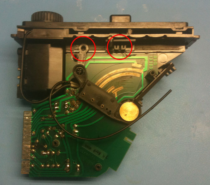
The contact arm had become disconnected from the "mode selector" ****. I popped the **** off with pliers, reattached the arm, put the **** back on, hooked everything back up and voila, A/C and blower running again:

So seeing how the design is very robust and couldn't possibly have come apart by itself, I started to think about how this had happened. My best guess is that one day when I was cleaning the interior of the car, I noticed that the arrows on the A/C head unit ***** were pointing the wrong way (i.e. away from the temperature settings and mode settings). I think I then popped off the ***** and rotated them the correct way and re-inserted them, which happened to dislodge the contact arm. Since it isn't my daily driver, I didn't notice that the blower wasn't working until the next time I drove it, and failed to make the connection with the **** swap. So I guess the moral of the story (if there is one) is to be careful when removing and re-inserting the A/C control head *****.
One final question: When I had it apart, there were several "wires to nowhere" (see photo above). One of them was flopping around in the path of the contact arm. I reinserted them into these plastic grooves that appeared to be designed to hold them. I am guessing that they are some type of temperature sensor, but am not sure of their function. [Edit] After looking at some other posts, they appear to be light conduits. Oops. I guess I'll hook them up the next time I tear it apart (probably when the Gruner relay explodes).
Anyway, much thanks to Dr. Bob and Mrmerlin for their suggestions. If anyone finds this post in the future for a similar problem, these links helped me out a great deal:
Pirtle's "How to remove the center console":
http://members.rennlist.com/pirtle/svc_cons.html
Wally's excellent writeup on the HVAC system:
http://www.928gt.com/t-wallyhvac.aspx
I then tried Mrmerlin's suggestion, and pulled relay V to check it for corrosion, but on my car, "relay" V is actually the flasher. So I moved on to the control head, and pulled it out.
Lo and behold, the second I popped the cover off it, the problem was obvious:
The contact arm had become disconnected from the "mode selector" ****. I popped the **** off with pliers, reattached the arm, put the **** back on, hooked everything back up and voila, A/C and blower running again:
So seeing how the design is very robust and couldn't possibly have come apart by itself, I started to think about how this had happened. My best guess is that one day when I was cleaning the interior of the car, I noticed that the arrows on the A/C head unit ***** were pointing the wrong way (i.e. away from the temperature settings and mode settings). I think I then popped off the ***** and rotated them the correct way and re-inserted them, which happened to dislodge the contact arm. Since it isn't my daily driver, I didn't notice that the blower wasn't working until the next time I drove it, and failed to make the connection with the **** swap. So I guess the moral of the story (if there is one) is to be careful when removing and re-inserting the A/C control head *****.
One final question: When I had it apart, there were several "wires to nowhere" (see photo above). One of them was flopping around in the path of the contact arm. I reinserted them into these plastic grooves that appeared to be designed to hold them. I am guessing that they are some type of temperature sensor, but am not sure of their function. [Edit] After looking at some other posts, they appear to be light conduits. Oops. I guess I'll hook them up the next time I tear it apart (probably when the Gruner relay explodes).
Anyway, much thanks to Dr. Bob and Mrmerlin for their suggestions. If anyone finds this post in the future for a similar problem, these links helped me out a great deal:
Pirtle's "How to remove the center console":
http://members.rennlist.com/pirtle/svc_cons.html
Wally's excellent writeup on the HVAC system:
http://www.928gt.com/t-wallyhvac.aspx
09-03-2010, 10:18 AM
#5
Rennlist Member
Rennlist Site Sponsor

Glad that you got it fixed! Sorry that I was late to the party...
"The coil is grounded (85) thru switches in the HVAC control head."
That is wrong. As you pointed out, pin 85 is hard-grounded to bus 31. The power to the coil comes from Fuse #6 thru one of several switches in the head unit.
I have no idea why I screwed that up...
"The coil is grounded (85) thru switches in the HVAC control head."
That is wrong. As you pointed out, pin 85 is hard-grounded to bus 31. The power to the coil comes from Fuse #6 thru one of several switches in the head unit.
I have no idea why I screwed that up...