

'88 Flex Plate and Crank End Play Check Procedure w/pics
 01-03-2010, 01:01 AM
#1
Three Wheelin'
Thread Starter
Join Date: Sep 2007
Location: Ridgecrest, California
Posts: 1,363
Likes: 0
Received 149 Likes
on
33 Posts
Over the last couple of weeks, I had the chance to get under Idaho and perform this check since I'm fairly certain it has not been performed on the car to date. This is a simplified procedure with not so many pictures but I'd thought I'd share with my fellow newbies that might want to try this check for themselves. This check should be performed regularly to measure the wear on the Thrust Bearing and release any existing flex plate tension that would contribute to Thrust Bearing wear. I believe this check is only critical on 32v engines with automatic transmissions. Others on this forum may have more info on this last statement.
First lift the car so it is safe and secure and plenty of room underneath to work.
Remove the rear belly pan and the front belly pan.
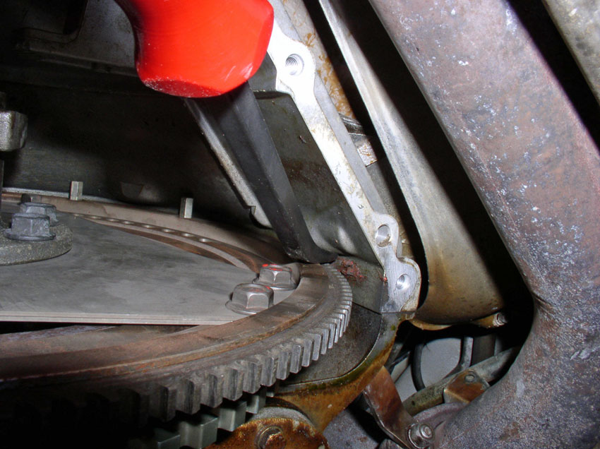
If you have the stock exhaust installed with heat shields and you've never taken the flywheel cover off, you will probably have to drop the exhaust system from the exhaust manifold a few inches in order to get at the rearmost bolts of the flywheel cover. The flywheel cover has six 13mm bolts holding it in place (3 bolts on each side) and the two rearmost bolts are right above the exhaust. See pic below.
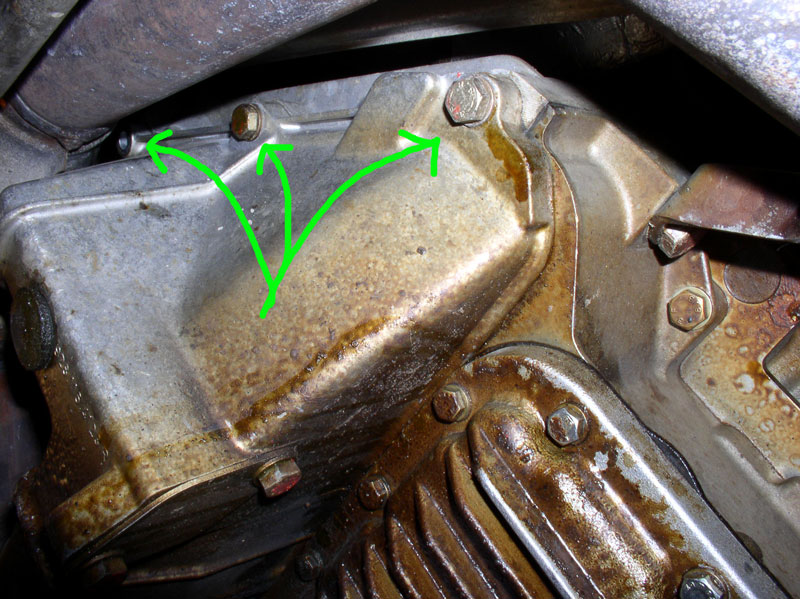
I had to remove the six exhaust flange bolts/nuts (3 on each exhaust manifold) and detach the air pump injection tube from the connection bolt near the exhaust manifold flange. I supported the exhaust system with a small hydraulic floor jack while I removed the two rearmost bolts on the flywheel cover. Then I removed the other four 13mm bolts from the flywheel cover and removed the cover (see pic below). I decided that I would not replace the 2 rearmost bolts in the flywheel cover since I'd be taking the cover off annually to perform this check. If you also choose to take this route, after the flywheel cover is removed, you can reconnect the exhaust sytem and air pump injection line as before and remove the floor jack to make more room. The flywheel cover will be re-installed with four 13mm bolts instead of six.
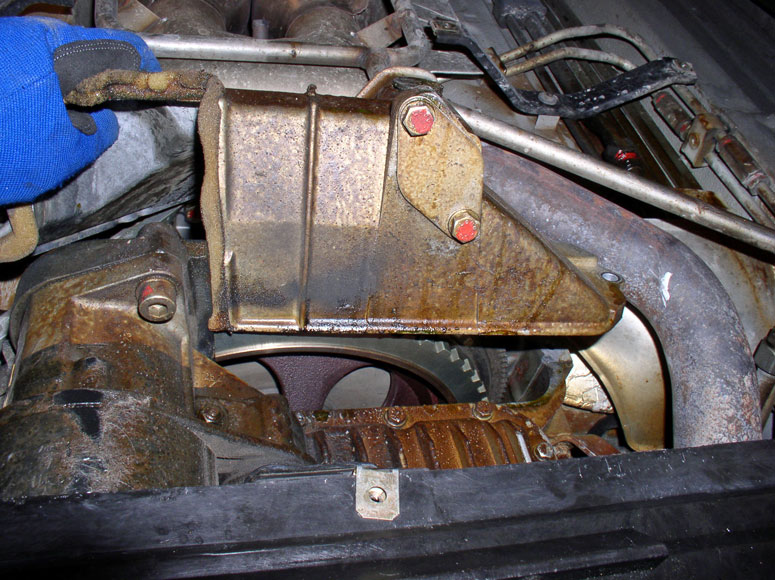
After the cover is removed, the flywheel is exposed.
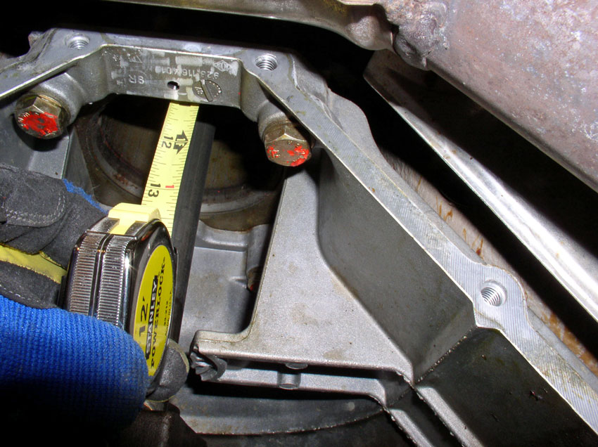
I took a picture of the front Torque Tube bearing for historical purposes...
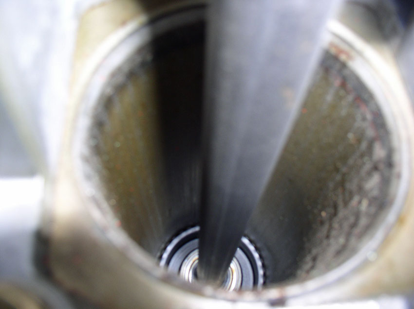
...and measured the distance between the bearing and the front of the Torque Tube (TT) casing. It's just under 11.25". I will check this measurement next year at this time to see if there is any movement. Idaho has about 25K miles on it.
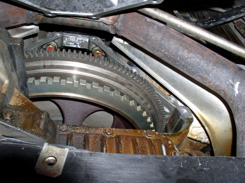
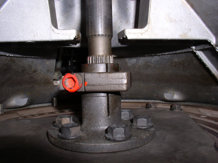
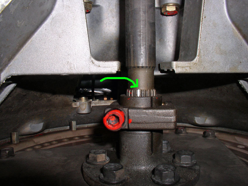
Next, I checked the flex plate tension at the TT clamp. You will need to rotate the engine (crank) clockwise enough so you can get access to the 8mm allen head bolt on the TT clamp.
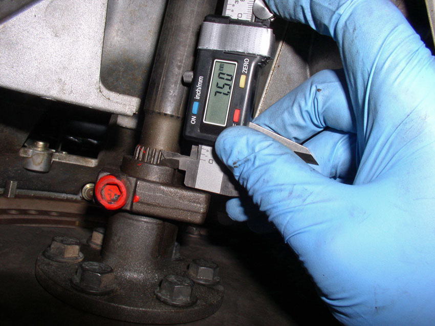
I then used a digital micrometer to mesure the amount of spline exposed toward the rear of the clamp. I measured 7.5mm before releasing the clamp and flexplate tension.
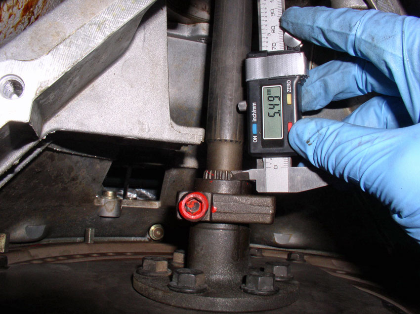
After loosening the allen head bolt, you can actually watch the clamp slide rearward on the splines as the tension is released from the flex plate. I took another measurement after loosening the bolt and I measured about 5.5mm. There was about 2mm of tension on the flexplate which results in forward pressure on the crank Thrust Bearing.
Next, I marked one of the splines with white paint (after tension was released) starting at the rear facing surface of the clamp (see pic below). The next time I check the flex plate tension, I should be able to tell if the clamp has moved visually indicated by any gap between the white mark and the rearward clamp face.
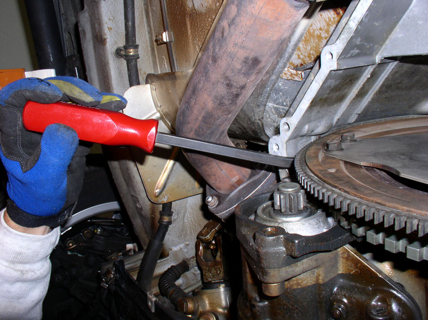
While the clamp was still loose, I checked the crank end play. Using a small pry bar, lever against the engine block and flywheel to move the flywheel rearward. It does not take a lot of force.
Then using the digital micrometer, pick a suitable location to measure distance between the engine block and flywheel. In this case the distance is 19.76mm.
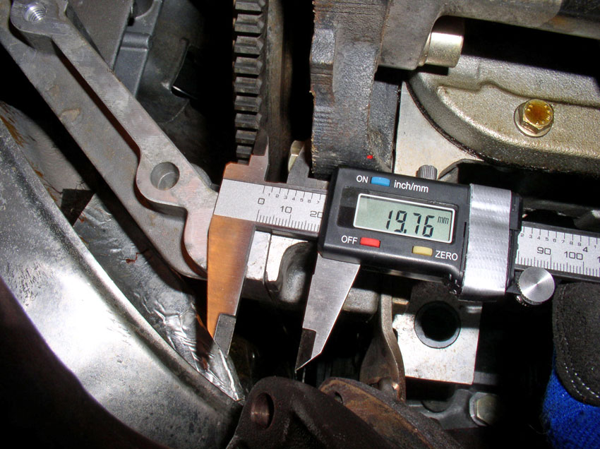
While holding the micrometer in place, take the pry bar and now lever against the bellhousing and flywheel to move the flywheel forward toward the front of the car (see pic below).
You should see the distance close on the micrometer. My distance closed to a distance of 19.56mm for a crank endplay measurement of 0.2mm. The WSM states new endplay is between 0.11mm and 0.31mm with a wear limit of 0.4mm. This measurement indicates the end play is within spec. If you record the measurements each year, you can monitor, regularly, any changes in Thrust Bearing wear.
To finish this check procedure, I levered the flywheel rearward and torqued the allen head clamp to 65 Ftlbs. Then installed the flywheel cover and installed the four forward 13mm bolts and torqued these to 15 Ftlbs.
After that, you can replace the front then rear belly pans and safely lower the car.
Feel free to comment or add any advice or improvements to this simple procedure. As always, THANKS for reading!
First lift the car so it is safe and secure and plenty of room underneath to work.
Remove the rear belly pan and the front belly pan.
If you have the stock exhaust installed with heat shields and you've never taken the flywheel cover off, you will probably have to drop the exhaust system from the exhaust manifold a few inches in order to get at the rearmost bolts of the flywheel cover. The flywheel cover has six 13mm bolts holding it in place (3 bolts on each side) and the two rearmost bolts are right above the exhaust. See pic below.
I had to remove the six exhaust flange bolts/nuts (3 on each exhaust manifold) and detach the air pump injection tube from the connection bolt near the exhaust manifold flange. I supported the exhaust system with a small hydraulic floor jack while I removed the two rearmost bolts on the flywheel cover. Then I removed the other four 13mm bolts from the flywheel cover and removed the cover (see pic below). I decided that I would not replace the 2 rearmost bolts in the flywheel cover since I'd be taking the cover off annually to perform this check. If you also choose to take this route, after the flywheel cover is removed, you can reconnect the exhaust sytem and air pump injection line as before and remove the floor jack to make more room. The flywheel cover will be re-installed with four 13mm bolts instead of six.
After the cover is removed, the flywheel is exposed.
I took a picture of the front Torque Tube bearing for historical purposes...
...and measured the distance between the bearing and the front of the Torque Tube (TT) casing. It's just under 11.25". I will check this measurement next year at this time to see if there is any movement. Idaho has about 25K miles on it.
Next, I checked the flex plate tension at the TT clamp. You will need to rotate the engine (crank) clockwise enough so you can get access to the 8mm allen head bolt on the TT clamp.
I then used a digital micrometer to mesure the amount of spline exposed toward the rear of the clamp. I measured 7.5mm before releasing the clamp and flexplate tension.
After loosening the allen head bolt, you can actually watch the clamp slide rearward on the splines as the tension is released from the flex plate. I took another measurement after loosening the bolt and I measured about 5.5mm. There was about 2mm of tension on the flexplate which results in forward pressure on the crank Thrust Bearing.
Next, I marked one of the splines with white paint (after tension was released) starting at the rear facing surface of the clamp (see pic below). The next time I check the flex plate tension, I should be able to tell if the clamp has moved visually indicated by any gap between the white mark and the rearward clamp face.
While the clamp was still loose, I checked the crank end play. Using a small pry bar, lever against the engine block and flywheel to move the flywheel rearward. It does not take a lot of force.
Then using the digital micrometer, pick a suitable location to measure distance between the engine block and flywheel. In this case the distance is 19.76mm.
While holding the micrometer in place, take the pry bar and now lever against the bellhousing and flywheel to move the flywheel forward toward the front of the car (see pic below).
You should see the distance close on the micrometer. My distance closed to a distance of 19.56mm for a crank endplay measurement of 0.2mm. The WSM states new endplay is between 0.11mm and 0.31mm with a wear limit of 0.4mm. This measurement indicates the end play is within spec. If you record the measurements each year, you can monitor, regularly, any changes in Thrust Bearing wear.
To finish this check procedure, I levered the flywheel rearward and torqued the allen head clamp to 65 Ftlbs. Then installed the flywheel cover and installed the four forward 13mm bolts and torqued these to 15 Ftlbs.
After that, you can replace the front then rear belly pans and safely lower the car.
Feel free to comment or add any advice or improvements to this simple procedure. As always, THANKS for reading!
 01-03-2010, 01:20 AM
#2
Drifting

To measur the thrust bearing free play, you will never get good repeatability by using a caliper. Best to use a dial gage for this. Like in this thread..
https://rennlist.com/forums/928-foru...pictorial.html

https://rennlist.com/forums/928-foru...pictorial.html
01-03-2010, 04:54 AM
#4
Rennlist Member
There isn't much steel underneath to act as a firm base for the end play gauge. Tricky to use the exhaust pipes for this purpose, though doable.
But, you can take a small floor jack to pin a piece of steel rectangular tubing against the bottom of the car and use it as a mount for the magnetic base. Just don't lift the car off the jackstands.
But, you can take a small floor jack to pin a piece of steel rectangular tubing against the bottom of the car and use it as a mount for the magnetic base. Just don't lift the car off the jackstands.
01-03-2010, 06:13 AM
#5
Rennlist Member
Excellent photo's and good report. Agree withthe comment to use a dial gauge for the end float check though.
As someone who was heavily involved in TBF investigations some 10 years ago I would be concerned that you detected this lateral movement. To me this suggests you have "TBF susceptability". The flex plate should not move- plain and simple. I did not suffer TBF but I could not stop the clamp from moving. After resetting, it only took about two weeks and it was back with about 3mm pre-tension. I could tell when this happened because I could feel a small but annoying vibration at exactly 3050 rpm when cruising in top gear [about 140 kph or roughly 88 mph]. If you feel this or have felt it be warned.
Constantine's clamp solution is the ideal approach, I see there is now another option with an auxiliary clamp [PKlamp] which is also quite a c lever piece of lateral thinking although I would be interested to see some lab tests to prove the degree of effectiveness of that approach which logically should be better than stock at the very least.
I still use the loctite approach [I believe I was the second owner to try this after Earl Gilstrom came up with the idea]. In your position I would not have re-clamped without the loctite or one of the other solutions so monitor your set up carefully. Apologies but I cannot remember for sure the Loctite number but I have a feeling it was Loctite 270. You degrease with carb cleaner [or something equally appropriate first] and then work the Loctite into the splines best you can moving the assembly backwards and forwards. You then leave it for 24 hours to set before placing any load on it.
It worked on my late S4 and it is working on my GTS chassis with my late S4 engine- the original GTS engine suffered terminal TBF which is why I was able to purchase this superb example for a giveaway price. I recovered the crankshaft after polishing out the thrust face but in current state it would have a logical end float of 0.5mm which is just outside the formally allowable range, but would still work OK I suspect- if I can ever get round to it. It will be academic if I decide to force induct my motor- I am confident the loctite will still hold it.
By the way, when I wrecked my S4 four years ago, the enigne was pushed back in the chassis, the bel housing cracked, the drive bent at the taper knuckle but the flex plate clamp [with Loctite] held in the middle of all that! It now holds my current flex plate [I think we re-used the S4 flexplate].
Regards
Fred R
01-03-2010, 07:25 AM
#6
Addict
Lifetime Rennlist
Member
Lifetime Rennlist
Member
There isn't much steel underneath to act as a firm base for the end play gauge. Tricky to use the exhaust pipes for this purpose, though doable.
But, you can take a small floor jack to pin a piece of steel rectangular tubing against the bottom of the car and use it as a mount for the magnetic base. Just don't lift the car off the jackstands.
But, you can take a small floor jack to pin a piece of steel rectangular tubing against the bottom of the car and use it as a mount for the magnetic base. Just don't lift the car off the jackstands.
01-03-2010, 08:53 AM
#7
Rennlist Member
I would be concerned about using 270 because you have to take out the TT someday to replace the bearings. 270 is intended to make a connection that doesn't get disassembled. How do you remove it? Heat up with torch or heat gun and then use MEK on the bolt and bolt hole threads to clean? Loctite 262 is made to "someday" be taken apart. Perhaps you used 262? Just curious because I am putting the PKlamp on next time I check and want to be very sure my flex plate stays locked.
Last edited by jeff spahn; 01-03-2010 at 09:00 AM. Reason: Add to data
Trending Topics
01-03-2010, 10:00 AM
#9
Rennlist Member
Could you elaborate on the 25MM TT and factory shims. I am not familiar with that.
01-03-2010, 12:05 PM
#10
Rennlist Member
I would be concerned about using 270 because you have to take out the TT someday to replace the bearings. 270 is intended to make a connection that doesn't get disassembled. How do you remove it? Heat up with torch or heat gun and then use MEK on the bolt and bolt hole threads to clean? Loctite 262 is made to "someday" be taken apart. Perhaps you used 262? Just curious because I am putting the PKlamp on next time I check and want to be very sure my flex plate stays locked.
We had no problems breaking the Loctite seal when we dismantled the S4 wreck but in all fairness I was a bit concerned about that possibility. Note that the pinch bolt is not Loctited- there is no need for that and if it was, you would not use this particular variant. The archives will probably yield the grade recommended but 270 is indeed intended for a permanent joint. Once set in position, there should be no need to change it in he future unless you rebuild the torque tube bearings. If you did get stuck remember the 6 bolts on the coupling flanges can be undone as an alternative.
Remember, when TBF does set in, invariably there will be no fore-warning and the first people are aware the problem has manifested itself is when they come to start the car next time and it has seized because the white metal bearing material has welded it up. By this time, the bearing shells have probably spun and the crankcase is history. If your flex plate has a history of moving on its splines I would not drive it until you have implemented one of the accepted robust solutions but that is my opinion. Indeed, I would not drive any S4/GTS auto that I owned without this mod implemented, history or not.
Regards
Fred
01-03-2010, 12:53 PM
#11
Rennlist Member
I seem to remember that the grade of loctite recommended was 290 but I could not get that locally so purchased 270 instead.
As I am aware, the only difference is that 290 tends to work its way through threaded joints without dissassembly so not really of concern in our joint design if you can wet the surface. Both 270 and 290 are specified to break up when heated to 250C and have similar properties when cured. Off the car it was easy to remove, but on the car may be more difficult.
Make no mistake, I like Constantine's design, it is a very elegant mechanical design and would have no hesitation about using it. Te original Porsche design is scandalous for a car of this class and the consequences it appears to have caused. For the other clamp design, I would like to know a bit more about it before using it.
Regards
Fred
01-03-2010, 12:55 PM
#12
Three Wheelin'
Thread Starter
Join Date: Sep 2007
Location: Ridgecrest, California
Posts: 1,363
Likes: 0
Received 149 Likes
on
33 Posts
Thanks ALL for the great feedback and advice. I have already purchased and have in hand 2 of Constantine's Superclamps and plan to install one of them next on Virginia ('87) - my wife's daily driver. The second clamp I plan to install on Idaho ('88) - my wife's garage queen. That will be later but fortunately, Idaho does not get driven a lot. I'm also interested in the PKlamp as a simple fix and I understand Roger sells these. I was thinking of getting one just to try it out and maybe install it on Oregon ('87) - my next daily driver. THANKS again for the insight!
01-03-2010, 03:52 PM
#13
Addict
Rennlist Member
Rennlist Member
Dwayne, see PET on what kind of setup '83-85 automatics have besides same factory clamp all 4sp automatics use.
01-03-2010, 07:35 PM
#14
Race Director
great write up dwayne!! I did the same thing years ago on sharky...& ended up with exactly the same endplay results even with 140K+ on the engine!
https://rennlist.com/forums/928-foru...ing-check.html
https://rennlist.com/forums/928-foru...ing-check.html
01-03-2010, 07:38 PM
#15
Rennlist Member
As the fun of dropping the exhaust may be enough to discourage some from committing to do this essential check on auto trans cars, the hacksaw blade makes quite short work of the back two lower bell housing bolts: details & rational described here some years ago.