

Stroker Scraper Kit

Man of many SIGs
Rennlist Member
Rennlist Member

Joined: May 2005
Posts: 8,724
Likes: 12
From: Florida, USA

Rennlist Member
Joined: Feb 2003
Posts: 29,828
Likes: 218
From: saratoga, ca
So, what is the main purpose of the scraper system?
if you are dry sumped, is there no real reason for the system?
If the need is power based, Joe and mark have the same rear wheel hp, yet one is dry sumped and the other is not. It is a very interesting product, and its great that Carl is coming up with such inovated products, but what is the problem and if there is one, who is likely to have it?
Rest in Peace
Rennlist Member
Rennlist Member
Joined: May 2006
Posts: 9,903
Likes: 2
From: Bird lover in Sharpsburg
Nordschleife Master
Joined: Jan 2009
Posts: 5,609
Likes: 84
From: MA
Ok, now that the pros have spoken (and I've partially recovered from today's GDP release with a bottle of wine, but that's another story), here's some amateur speculation of what one might try in an oil control system.
Three ideas, all copied from other engines:
(1) an integrated spacer-scraper cut from aluminum
(2) curved oil pan fin extensions
(3) windage screen over the sump deep end
I tried to do what Kevin Johnson suggested and think about it from the original designer's perspective. First, understand what strategy he took. How is the design supposed to work. Second, what constraints the original designer faced.
With the risk of being philosophical, one has to ask the question how to improve on the original design. One could try to be just better than the original designer, and solve the problem better within the constraints than he did. Absent a major technological breakthru, that's not likely. Alternatively, one could relax some of the constraints that the original designer faced and then alter his strategy slightly.
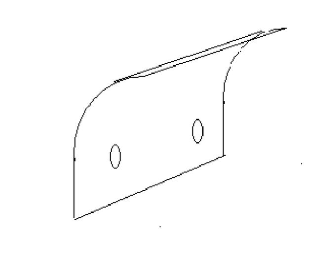
So here's what I am thinking about. First, cut a 3/8 inch spacer for the pan than integrates a crank scraper. The crank scraper would be on the passenger side. This would be too expensive for a car company's accountants, but might be just fine for someone like me who's paying $250 for the spacer anyway.
SpacerScraper.jpg
The original designer IMO faced the budget constraint, mainly having to produce a pan that is easy to cast. Without the casting constraint, the fins on the bottom of the oil pan could take much more interesting shapes. One such shape is this:
TornadoPump.jpg
Bolt (or weld, depending on a lot of things) these curved scrapers to the sides of the existing oil pan fins. Now, we have these scrapers that are at 45 degree or so angle relative to the crank centerline, so the windage gets under the curved part just right. The 45-degree angle deflects the oil and air towards the deep end of the sump.
In addition, the curve helps in the following way. I believe (but do not know) that the screen that Kevin, Greg, and Louis all use in their systems mainly functions as a device that prevents the oil from being reflected or bounced of from the oil pan bottom back to the crank. That's a big problem and needs a solution. I think that the curved part would use the velocity of the separating oil to screen the oil under the curve and stop the reflection of oil from the pan bottom. The advantage over a screen would be that the "tornado pump" that moves oil towards the deep part of the sump would still work.
Finally, there's a place for the unidirectional screen. These screens seem to help in all the systems that I've seen in two ways. Mostly this is learned from reading Kevin's posts on the internet. First, because they reduce the velocity, they stop reflection or bounce back. Second, because they reduce the velocity, when oil droplets hit oil surface, they trap less air in.
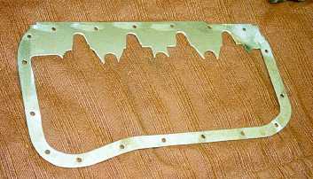
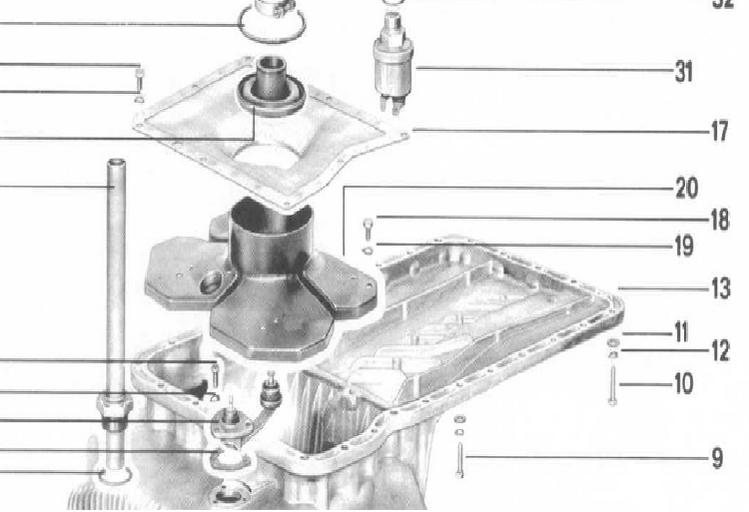
How about placing a unidirectional screen on top of the deep part of the sump? That is, make piece #17 of the old school 928 engine from that unidirectional screen stuff:
WindageScreen.jpg
What these three measures do not address is oil draining from the heads.
My thinking has benefited from a lot hints that Jim Morton gave me over the phone a couple of months ago. Just recently, I've started to really understand that conversation. Errors and misunderstandings are all me, of course!
Critique welcome!
Three ideas, all copied from other engines:
(1) an integrated spacer-scraper cut from aluminum
(2) curved oil pan fin extensions
(3) windage screen over the sump deep end
I tried to do what Kevin Johnson suggested and think about it from the original designer's perspective. First, understand what strategy he took. How is the design supposed to work. Second, what constraints the original designer faced.
With the risk of being philosophical, one has to ask the question how to improve on the original design. One could try to be just better than the original designer, and solve the problem better within the constraints than he did. Absent a major technological breakthru, that's not likely. Alternatively, one could relax some of the constraints that the original designer faced and then alter his strategy slightly.
So here's what I am thinking about. First, cut a 3/8 inch spacer for the pan than integrates a crank scraper. The crank scraper would be on the passenger side. This would be too expensive for a car company's accountants, but might be just fine for someone like me who's paying $250 for the spacer anyway.
SpacerScraper.jpg
The original designer IMO faced the budget constraint, mainly having to produce a pan that is easy to cast. Without the casting constraint, the fins on the bottom of the oil pan could take much more interesting shapes. One such shape is this:
TornadoPump.jpg
Bolt (or weld, depending on a lot of things) these curved scrapers to the sides of the existing oil pan fins. Now, we have these scrapers that are at 45 degree or so angle relative to the crank centerline, so the windage gets under the curved part just right. The 45-degree angle deflects the oil and air towards the deep end of the sump.
In addition, the curve helps in the following way. I believe (but do not know) that the screen that Kevin, Greg, and Louis all use in their systems mainly functions as a device that prevents the oil from being reflected or bounced of from the oil pan bottom back to the crank. That's a big problem and needs a solution. I think that the curved part would use the velocity of the separating oil to screen the oil under the curve and stop the reflection of oil from the pan bottom. The advantage over a screen would be that the "tornado pump" that moves oil towards the deep part of the sump would still work.
Finally, there's a place for the unidirectional screen. These screens seem to help in all the systems that I've seen in two ways. Mostly this is learned from reading Kevin's posts on the internet. First, because they reduce the velocity, they stop reflection or bounce back. Second, because they reduce the velocity, when oil droplets hit oil surface, they trap less air in.
How about placing a unidirectional screen on top of the deep part of the sump? That is, make piece #17 of the old school 928 engine from that unidirectional screen stuff:
WindageScreen.jpg
What these three measures do not address is oil draining from the heads.
My thinking has benefited from a lot hints that Jim Morton gave me over the phone a couple of months ago. Just recently, I've started to really understand that conversation. Errors and misunderstandings are all me, of course!
Critique welcome!
Rennlist Member
Joined: May 2001
Posts: 4,871
Likes: 40
From: Puyallup, WA
Tuomo,
Just a couple of observations:
I think having the scrapers on the spacer is going to put them too low on the crank to be effective, unless they are actually tilted up toward the centerline of the crank. All the scrapers I've seen to date for the 928 sit up in girdle, higher than the pan rail.
Windage screen won't keep oil in the sump if the sump is full and the car is subject to lateral G's, it's not that strong of a barrier.

Racer
Joined: Jul 2004
Posts: 409
Likes: 0
Ok, now that the pros have spoken (and I've partially recovered from today's GDP release with a bottle of wine, but that's another story), here's some amateur speculation of what one might try in an oil control system.
Three ideas, all copied from other engines:
(1) an integrated spacer-scraper cut from aluminum
(2) curved oil pan fin extensions
(3) windage screen over the sump deep end
I tried to do what Kevin Johnson suggested and think about it from the original designer's perspective. First, understand what strategy he took. How is the design supposed to work. Second, what constraints the original designer faced.
With the risk of being philosophical, one has to ask the question how to improve on the original design. One could try to be just better than the original designer, and solve the problem better within the constraints than he did. Absent a major technological breakthru, that's not likely. Alternatively, one could relax some of the constraints that the original designer faced and then alter his strategy slightly.
So here's what I am thinking about. First, cut a 3/8 inch spacer for the pan than integrates a crank scraper. The crank scraper would be on the passenger side. This would be too expensive for a car company's accountants, but might be just fine for someone like me who's paying $250 for the spacer anyway.
Aside: John Beardmore does fantastic work. I really admire him. The subsequent mods he does to the Fiat dry sump (based on the Ford Kent Cosworth edition) are brilliant. Triumph also used screening like this in the Mark 1 2000 straight six until accounting nabbed them.
Adam is correct about the plane defined by the oil pan rail of the block. It is borderline to be effective as a primary scraper. Particularly so if you are using a later variant of the Porsche crank where the swept diameter of the counterweights is "above" that plane, i.e. interior to the block.
Adam is also correct about messing with the bedplate (but more on that in a bit) unless you are willing to regularly advise an align hone or check. Note the elaborate factory fastener torque sequence.
The plane on the bedplate defined by the fastener pads for the 10mm studs is an existing platform that will support the Beardmore style of scraper but which will still allow intersection with the full swept path of the rotating assembly. Louie and Greg both have used it. [Edit: I think Louie actually used the plane slightly above that one with the 8mm fasteners]
The spacer is a great idea -- 3/8" (9.925mm) is about what Porsche dropped the 944 pan (8mm). Just remember that this will affect other components (starter, for example -- I am sure there are others). To minimize the impact, while you are having the spacer made, have receiver grooves cut for a polymer cord insert -- look at a Ford Zetec E alloy sump casting (Focus model). [Edit: Make that the Raceline sump for the Zetec. Or look at the later alloy sump for a Ford 2.3 OHC or the alloy sump for a GM 4.3 V6.]
The original designer IMO faced the budget constraint, mainly having to produce a pan that is easy to cast. Without the casting constraint, the fins on the bottom of the oil pan could take much more interesting shapes. One such shape is this:
Attachment 395816
Bolt (or weld, depending on a lot of things) these curved scrapers to the sides of the existing oil pan fins. Now, we have these scrapers that are at 45 degree or so angle relative to the crank centerline, so the windage gets under the curved part just right. The 45-degree angle deflects the oil and air towards the deep end of the sump.
In addition, the curve helps in the following way. I believe (but do not know) that the screen that Kevin, Greg, and Louis all use in their systems mainly functions as a device that prevents the oil from being reflected or bounced of from the oil pan bottom back to the crank. That's a big problem and needs a solution. I think that the curved part would use the velocity of the separating oil to screen the oil under the curve and stop the reflection of oil from the pan bottom. The advantage over a screen would be that the "tornado pump" that moves oil towards the deep part of the sump would still work.
Finally, there's a place for the unidirectional screen. These screens seem to help in all the systems that I've seen in two ways. Mostly this is learned from reading Kevin's posts on the internet. First, because they reduce the velocity, they stop reflection or bounce back. Second, because they reduce the velocity, when oil droplets hit oil surface, they trap less air in.
How about placing a unidirectional screen on top of the deep part of the sump? That is, make piece #17 of the old school 928 engine from that unidirectional screen stuff:
Attachment 395817
How about placing a unidirectional screen on top of the deep part of the sump? That is, make piece #17 of the old school 928 engine from that unidirectional screen stuff:
Attachment 395817
Last edited by Kevin Johnson; Oct 30, 2009 at 09:52 AM. Reason: not enough coffee: Elixir des Lebens
Racer
Joined: Jul 2004
Posts: 409
Likes: 0
One of the maintenance issues with the Panzerkampfwagens was that the factory engineers were continually trying to improve the designs because the [lives] of the occupants depended on it.
I cannot imagine anyone who might be related to the philosophy behind the current discussion and tanks in WWII. Hmmm. Maybe I can at that. France was pretty pissed off about that.
I cannot imagine anyone who might be related to the philosophy behind the current discussion and tanks in WWII. Hmmm. Maybe I can at that. France was pretty pissed off about that.
Last edited by Kevin Johnson; Oct 30, 2009 at 09:38 AM. Reason: being anal
Rennlist Member
Joined: Feb 2003
Posts: 29,828
Likes: 218
From: saratoga, ca
I guess I just dont understand what is trying to be improved. I think the panzer factory engineers were trying to improve safety by improving things that could be improved to make them safter or and more dependable. Does the scraper improve anything? save HP by reducing whipping loses? keep more oil in the pan for less chance of oil starvation? what about the fact that all that oil whipping around could assist with piston bottom and pin lubrication?
All the work is extremely interesting and from a flow perspective, i understand what can happen with such a contraption. BUT, what is the goal here?
Hasnt there been some engine failures with these types of devices installed?
I have a hard time thinking about using something like this, after 105 race days with a bone stock engine running the snot out of it and no issues, or hints of dependabilty issues.
One of the maintenance issues with the Panzerkampfwagens was that the factory engineers were continually trying to improve the designs because the [lives] of the occupants depended on it.
I cannot imagine anyone who might be related to the philosophy behind the current discussion and tanks in WWII. Hmmm. Maybe I can at that. France was pretty pissed off about that.
I cannot imagine anyone who might be related to the philosophy behind the current discussion and tanks in WWII. Hmmm. Maybe I can at that. France was pretty pissed off about that.
Racer
Joined: Jul 2004
Posts: 409
Likes: 0
Yes, it does. This is probably why Porsche used and continues to use the technology.
Yes.
I mentioned briefly in another thread that the use of crank scrapers in a dry sump pan increased the output of the engine by 5% at 6500 rpms.
Yes. There has been a lot of attention paid to the vector that can be imparted to oil in the pan towards the sump. Less attention has been paid to the slow return from the heads of foamed oil. Look at Louie's video. For the umpteenth time. This tripped up Porsche in the M96/M97 as well.
All the work is extremely interesting and from a flow perspective, i understand what can happen with such a contraption. BUT, what is the goal here?
Hasnt there been some engine failures with these types of devices installed?
I have a hard time thinking about using something like this, after 105 race days with a bone stock engine running the snot out of it and no issues, or hints of dependabilty issues.
Hasnt there been some engine failures with these types of devices installed?
I have a hard time thinking about using something like this, after 105 race days with a bone stock engine running the snot out of it and no issues, or hints of dependabilty issues.
Something to think about...
Rennlist Member
Joined: Feb 2003
Posts: 29,828
Likes: 218
From: saratoga, ca
you can see my videos. all shifts are at or near redline, you cant push the engine any harder than I am. WOT is WOT and redline is redline, and duration between drivers will be minimum. The times I run are top WC touring times at a track near you. After running 7 full racing seasons, and no issues, along with that engine taken apart and oil analysed to see what was happening, that could be a clue that things are good with wear patterns under extreme use.
you tell me of how this engine could be pushed harder at one of the most demanding tracks in the world.
http://www.youtube.com/watch?v=ddvWNNBDEp4
Anyway, if you are not racing the 928, its probably not an issue. 5% HP saved is very optimistic and not proven. for example, dry sumped vs non drysumped has not yeilded any HP gains in the countless dyno runs between Mark A and Joe F and their identical engines. in fact the stock set up from Joe , has generally made more HP. Plus, that number is very dependent on several factors. rate of change of acceleration , being the most dominant. are we talking quick revs , like blips for shifs, 1st gear or 5th gear??? These are HUGE factors for HP savings. Just saying 5%, is plain silly.
I would be more concerned with the return of the oil to the pan, as Greg B has mentioned. Factory designs vs us using napkin drawings of how it should be designed, is a little risky, in my opinion.
mk
I
Porsche had the same opinion in the final year where they hand selected engines to provide back door factory support. Those engines failed near the end of the season. I know you feel you push the car to its maxima. It could just be that there are other drivers that push it harder both at present and in the past.
Something to think about...