


Stroker Scraper Kit
Thread Starter
Developer
Joined: Dec 2001
Posts: 7,005
Likes: 64
From: Horicon, WI
Thank you Mike.
Tuomo, thats a good question. I'm in the shop right now, but should be able to show some pics and provide some small explanations later today. If you search, there is quite a bit on the internet on how crank scrapers work.
Tuomo, thats a good question. I'm in the shop right now, but should be able to show some pics and provide some small explanations later today. If you search, there is quite a bit on the internet on how crank scrapers work.
Pro
Joined: Nov 2003
Posts: 529
Likes: 0
From: Reston VA
Thought you might find this interesting...
We are developing a crack scraper and windage tray system for stroker cranks, and here are a couple pictures to show the process.
These are a mod to the crankscraper and windage tray system we co-developed with Ishihara-Johnson several years ago, and when I have the patterns finished these will go to IJ for manufacture like last time.
In addition to making changes for the longer stroke, we are also relieving the scraper for the larger bearing boss of the steel rods we are using in the big engines. This one is a 6.4L build.
The yellow marks indicate where more material needs to be removed, then I take the scraper off and into the shop to do so. The paint marks are burned off. The scraper is deburred and cleaned, then brought in for another fitting, and the process starts again.


Former Vendor
Joined: Feb 2005
Posts: 15,228
Likes: 2,530
From: Anaheim
I have a question about the scraper. There's a scraping blade on both sides of the crank. When the crank turns and whips oil with it, one of the blades will scrape oil below the blade and into the sump. That's good. However, the other blade will scrape oil above the blade. How will the system guide this oil that is scraped onto the upper side of the blade into the sump?
Real eye opener to suddenly realize that there is 20 quarts of oil being held above the crankshaft....in suspension....and to think about how quick this can happen with a wet sumped engine with 8 quarts. Of course, there is no sump tank to watch...so you'll never know this is happening...until the rod comes through the block.
Nordschleife Master
Joined: Jan 2009
Posts: 5,609
Likes: 84
From: MA
CrackScraper.jpg
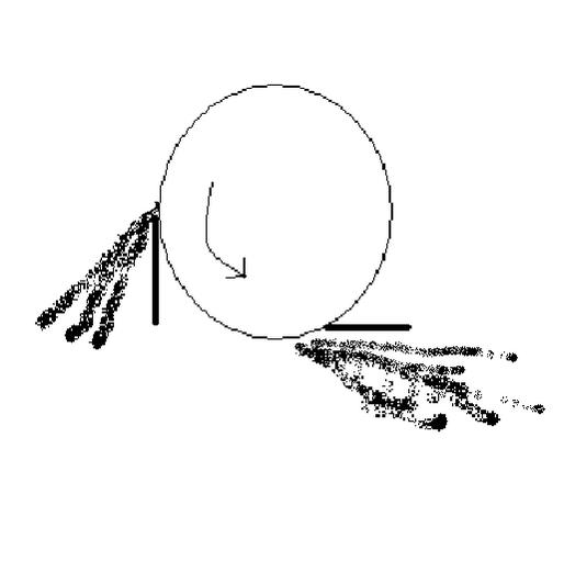
This way, the scraped oil from both scrapers will shoot to the sump.
Now, I understand that scraping is not the only concern with 928. It may be that what that second horizontal scraper is really doing is stopping the oil from surging from that side when the car corners. I don't know. I assume Kevin Johnson had his reasons. However, I am wondering about how the oil accumulating on top of the second horizontal scraper is supposed to find its way to the sump.
Former Vendor
Joined: Feb 2005
Posts: 15,228
Likes: 2,530
From: Anaheim
Yes, I do. Although you have removed the pictures and all reference to the pictures, for some unknown reason, the questions are still the same. Is the knife edge the leading edge, like you say, or is the rounded edge the leading edge?
Nordschleife Master
Joined: Jan 2009
Posts: 5,609
Likes: 84
From: MA
Moving on back to scrapers.
How did you solve the problem of cumulating oil above the scraper in your dry-sump example? Only installed a scraper on one side only?
I am looking at your web page at http://www.precisionmtrwerks.com/products/products.htm. These are interesting. Since I haven't tried anything yet amnd you have worked on these engiens for a long time, please consider the below juet as ignorant questions.
The pan spacer has to be part of the solution, because it allows for increased sump capacity. The pickup has to of course also be lowered.
I have one question about the pan spacer, though. With the pan spacer, the fins in the bottom of the oil pan are no longer as close to the crank as they used to be. Those fins are at 45 degree angle, and when the crank rotates (clockwise), the oil hits these fins and presumably gets deflected towards the front of the pan. I believe that this was one of the ideas that the original designer had in mind.

Doesn't installing the pan spacer eliminate this presumably beneficial effect? Would it make sense to install extensions to the fins in the bottom of the pan if used with the spacer?
The same question applies to the windage tray, both your and Kevin Johnson's. Doesn't the windage tray prevent the oil pan fins from doing their jobs?
The whole windage tray is a two edged sword, isn't it? On the one hand, it keeps the oil in the sump from hitting the crank when the car accelerates hard in some direction. That's good. On the other hand, it keeps the oil from draining back to the sump. That's bad. Since people are finding that installing a windage tray helps in many designs, it must be the case that the former effect must dominate the latter.
The following is pure speculation. One would think that for the windage tray to work, one would have to somehow use the energy of the oil spinning with the crank, scrape it off to shoot thru an opening in the windage tray. This opening in turn would have to be in a place that the surging oil can't reach easily from the bottom of the pan.
The whole sump oil flow seems to be all about designing passages thru which the oil only wants to go in one direction.
Last edited by ptuomov; Oct 27, 2009 at 08:18 PM.
Thread Starter
Developer
Joined: Dec 2001
Posts: 7,005
Likes: 64
From: Horicon, WI
Greg - you are right. The round nose is the leading edge and the chisel-point is the trailing edge. I removed the pictures - no mystery here. I can't sit at the keyboard for long and its faster to remove a picture that raises more questions than it answers.
Rennlist Stories
The Best Porsche Posts for Porsche Enthusiasts

Talos Takes Your 991 Porsche 911 GT3 to the Next Level for a Cool $1.13 Million
Verdad Gallardo
9 Vehicles Porsche Helped Engineer that Aren't Porsches
Verdad Gallardo
9 Features and Characteristics That Only Porsche People Understand
Verdad Gallardo
I've Written 500 Rennlist Articles: Here's How Porsche Has Changed Along the Way
Joe Kucinski
10 Most Unnecessary Porsches Ever Built (And Why We Love Them)
Verdad Gallardo
Porsche 911 GT3 S/C vs 718 Spyder RS: 10 Categories, One Winner
Joe Kucinski
This Builder Is Turning Heads With Its Slantnose 911 Creation
Verdad Gallardo
Porsche 911 GT3 Artisan Edition Pays Homage to Japanese Culture
Verdad Gallardo
Porsche Reveals Coupe Variant of the Electric Cayenne With a Fresh Look
Verdad Gallardo
Thread Starter
Developer
Joined: Dec 2001
Posts: 7,005
Likes: 64
From: Horicon, WI
Tuomo,
maybe this will help. I'm going to show two iterations in the current crankshaft scraper and windage tray system.
Keep in mind that the photos at the start of this post are of only parts of this kit -not the whole thing installed as-run. There are many separate pieces that assist with getting the oil down and keeping it down.
These pics represent the state of the scraper and windage tray system when it was here in 2007. Note the open center section. This is when we partyicipated with IJ in a redesign of the system and making new and better patterns for the scrapers.
Thread Starter
Developer
Joined: Dec 2001
Posts: 7,005
Likes: 64
From: Horicon, WI
...and here is what that 2007 development produced: the 2008 version.
Note the increased use of unidirectional screening under the crank center. Kevin Johnson's excellent idea. It allows oil to flow thru in one direction easily, not so easily to get back thru the other way.
The four L-shaped items on the floor are diverters that divert the oil coming down from the heads around the counterweights instead of running right into the spinning counterweight like it does OEM.
Also note the hinged gates. They are up-side down in this photo - of course they hang down from the engine when installed.
They allow oil to easily return to the front sump, yet under hard acceleration thay swing shut to prevent oil from climbing the ramp up to the rear of the pan where it will get into the rotating assembly.
The CW on bearings, oil, and entrained air is that main bearings can tolerate as much as 50% entrained air in the oil before they fail, but rod bearings will only handle a max of 30% entrained air in the oil before they fail.
Rennlist Member

Joined: Feb 2003
Posts: 29,828
Likes: 218
From: saratoga, ca
So, it kind of proves that if this is not designed absolutely correctly, that it could cause MUCH more of a risk than not having one. maybe Doty's motor met this fate. how would he know, unless he has a record of the accusump releasing oil, and what if it wasnt fast enough? could the bearings run dry at high rpm and the oil all being suspended above the crank?
I kind of like the fact that our engines. Mine, Joe's, and others like it, can be beat to snot, and not have any issues in a stock configuration.
why change???? Do we really understand what the real goal is here?
Confused.
I kind of like the fact that our engines. Mine, Joe's, and others like it, can be beat to snot, and not have any issues in a stock configuration.
why change???? Do we really understand what the real goal is here?
Confused.
We had a custom dry sump pan, with a custom scraper (no names, here) that did this very thing....it would suck the dry sump tank empty when you did any steady state rpm's above 5,000 rpms. EMPTY! And it only took a few seconds, to do this. Of course, as soon as you let off and let the rpms drop back, the tank filled right back up. You had to be looking at the tank, in order to see it do this....or the rod bearings.
Real eye opener to suddenly realize that there is 20 quarts of oil being held above the crankshaft....in suspension....and to think about how quick this can happen with a wet sumped engine with 8 quarts. Of course, there is no sump tank to watch...so you'll never know this is happening...until the rod comes through the block.
Real eye opener to suddenly realize that there is 20 quarts of oil being held above the crankshaft....in suspension....and to think about how quick this can happen with a wet sumped engine with 8 quarts. Of course, there is no sump tank to watch...so you'll never know this is happening...until the rod comes through the block.
Rennlist Member
Joined: Feb 2003
Posts: 29,828
Likes: 218
From: saratoga, ca
If Im understanding you, wouldnt the one "scraper" be enough then? the vertical piece looks a little redundant. You would think that it should only be on one side to avoid the oil from being suspended during high rpm.
Based on what I've read on the internet, I would have assumed that the best way to install two scrapers would be as follows:
Attachment 395239
This way, the scraped oil from both scrapers will shoot to the sump.
Now, I understand that scraping is not the only concern with 928. It may be that what that second horizontal scraper is really doing is stopping the oil from surging from that side when the car corners. I don't know. I assume Kevin Johnson had his reasons. However, I am wondering about how the oil accumulating on top of the second horizontal scraper is supposed to find its way to the sump.
Rennlist Member
Joined: May 2001
Posts: 5,282
Likes: 16
From: Austin, TX

Carl, I too am thankful for your product development. Although, I'll probably never have need for this, I do benefit from several of your products currently installed on my 928.
Nordschleife Master
Joined: Jan 2009
Posts: 5,609
Likes: 84
From: MA
Doesn't the screen under the center section disable the deflectors in the bottom of the pan?