
Girdle oil passage modifications
 10-11-2009, 11:24 PM
#61
Racer

Join Date: Jul 2004
Posts: 409
Likes: 0
Received 0 Likes
on
0 Posts
However even after all the improvements I made to my oiling system...I was still seeing 3ish bar in turns...oddly enough most of them were right turns...the pressure didn't drop as much in left turns? Odd...very odd...
However after 4 run sessions totalling almost 1.5 hours on track....the oil was spotlessly clean...I've never seen oil that clean after hard running
However after 4 run sessions totalling almost 1.5 hours on track....the oil was spotlessly clean...I've never seen oil that clean after hard running
Scrubbing bubbles.

 10-12-2009, 12:04 AM
#62
Nordschleife Master
Thread Starter
I went out to the shop and grabbed a twenty foot section of PVC pipe and drilled spaced holes down its length on the drill press. I plugged one end with wax and made a port on the other in soft wax for me to shoot the garden hose sprayer down it. After the pipe filled with water and pressure built up the holes near the terminal end of the tube did not squirt as high as the ones near the front. It was not a big effect, though.
10-12-2009, 12:24 AM
#63
Nordschleife Master
Thread Starter
If you are concerned about the pressure dropping in the distributing passage at the section that I colored yellow in the earlier photos, making that passage wider will slow down the fluid and increase the pressure.
I am not suggesting that this girdle modification is an alternative to keeping the oil pan pickup submerged in oil or keeping the oil from being whipped into a chocolate milkshake. It's not. But it may be an alternative to the "Taylor" drilling of the crank.
10-12-2009, 08:38 AM
#64
Racer
Join Date: Jul 2004
Posts: 409
Likes: 0
Received 0 Likes
on
0 Posts
If you are concerned about the pressure dropping in the distributing passage at the section that I colored yellow in the earlier photos, making that passage wider will slow down the fluid and increase the pressure.
I am not suggesting that this girdle modification is an alternative to keeping the oil pan pickup submerged in oil or keeping the oil from being whipped into a chocolate milkshake. It's not. But it may be an alternative to the "Taylor" drilling of the crank.
I am not suggesting that this girdle modification is an alternative to keeping the oil pan pickup submerged in oil or keeping the oil from being whipped into a chocolate milkshake. It's not. But it may be an alternative to the "Taylor" drilling of the crank.
In the ensuing years I believe there were people that commented that this solution was inadequate for racing.
In a larger sense, this continuing internet pursuit is analogous to the recent, unsuccessful, almost decade long engineering efforts at Porsche to solve the M96/M97 issue. Huge effort and expense to try to correct the _symptoms_ of the problem rather than the _causes_ of the problem. There is a very expensive and hard earned lesson in there somewhere. It would probably make a wonderful lecture for beginning engineering students of what to watch out for.
10-12-2009, 10:06 AM
#65
Nordschleife Master
Thread Starter
Originally Posted by ptuomov
At every point when an oil passage splits from the distributing channel, the cross-sectional area of the distributing channel was brought down. That makes sense. Except at the 2/6 rod bearing split. That exception makes no sense.
I do not believe there is an exception. Some time ago, Erkka measured the cross sectional areas and posted a color coded chart. I don't have the figures in front of me but I remember the blue circular passage from the oil pump being larger than the green "well" area.At every point when an oil passage splits from the distributing channel, the cross-sectional area of the distributing channel was brought down. That makes sense. Except at the 2/6 rod bearing split. That exception makes no sense.
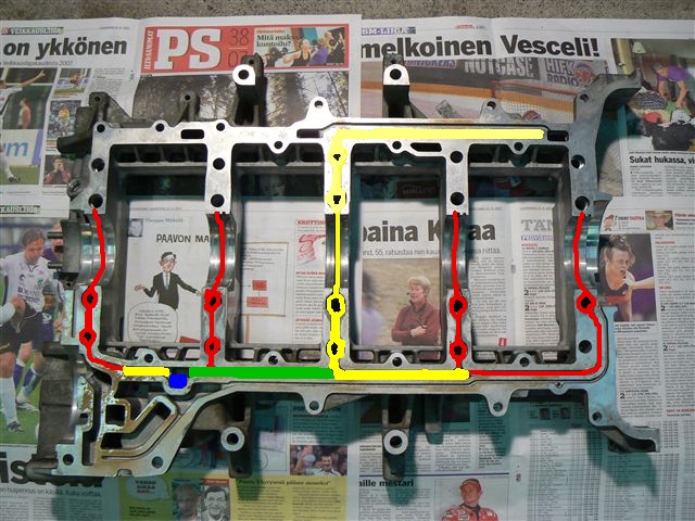
Blue = "the well" = 15mm wide round feed pipe from oil filter = 177mm^2
Green = 8.5mm wide x 16mm deep = 136mm^2
Yellow = 8.5mm wide x 10mm deep = 85mm^2
Light yellow = 7.5mm wide x 11 deep = 83mm^2
Red = 5mm wide x 5 mm deep = 25mm^2
"Yellow" includes both the short straight section from the blue section to the #1 main bearing and from the green section to the end of the #3 main bearing and towards the main bearing #4 and #5. "Light yellow" is the section from #3 main to what eventually leads to the upper right head.
In my opinion, it's clear that the first short section of the green passage should have a larger cross-sectional area than the rest of the green section. The cross-sectional area of the distributing passage does not change when the #2 main passage breaks off from the distributing channel. That looks like an error to me.
Now, let me just say again that it would be foolish to expect this kind of modifications to solve all the problems. For example, if the oil pickup gets uncovered because of the accelerations and/or because oil is not being returned to the sump, then no crank drilling or girdle modifications will solve that problem. What this can solve is the uneven distribution of oil to the main bearings 1, 2, 4, and 5.
10-12-2009, 05:48 PM
#66
Racer
Join Date: Jul 2004
Posts: 409
Likes: 0
Received 0 Likes
on
0 Posts
... Now, let me just say again that it would be foolish to expect this kind of modifications to solve all the problems. For example, if the oil pickup gets uncovered because of the accelerations and/or because oil is not being returned to the sump, then no crank drilling or girdle modifications will solve that problem. What this can solve is the uneven distribution of oil to the main bearings 1, 2, 4, and 5.
Everyone raise your hand who has had the oil pressure drop to zero during hard running in a wetsump 928 Porsche over the past 30 or so years. (??) Dropping to zero AFTER the bearings fail doesn't count.
When the pickup is uncovered the pressure will drop to zero. Granted that there is dampening in the stock type oil pressure gauges. On BMW spec racers installing an accurate and sensitive oil pressure gauge starts the terror.
I don't think the pickup being uncovered or insufficient oil return is really an issue at all in the 928.
What is an issue are pressure drops which indicate entrained air in the oil. When the entrained air is over about 30% bearing damage to the rods is highly likely. The damage is cumulative.
How will modifying the oil passages in the bedplate removed entrained air from the oil? Where will that removed air go? When you cross drill a crank where will that air go?
You must stop the air from being mixed into the oil in the first place as best you can. Dry sumps do this by removing the oil as quickly as possible.
Dry sumps condition the oil after it has been collected. If they don't, guess what, the bearings will fail. This periodically happens with dry sump systems that are pushed beyond their capacity. Sometimes this will only show up after hours and hours and hours on the track. It can be so transient in nature that it will disappear when the car comes into the pits and idles for a bit.
There has been a lot of research (look for recent SAE papers) on measuring aeration levels in real time. If the problem was simply pickups being uncovered or oil return issues this is almost trivial to solve.
10-12-2009, 10:37 PM
#67
Nordschleife Master
Thread Starter
First:
Then:
Kevin --
In my opinion, I have answered your question above, three times. Drilling the girdle will not remove air from the oil, and will not help with that issue. It might spread the air bubbles more evenly between the mains, but might not. I think I have consistently talked about distributing normal oil evenly, not curing the problems associated with the aerated oil.
On a somewhat related topic, a couple of months ago, you asked me to take a look at some of the Mazda four-banger cranks and compare them to 928's crank. I have looked at a couple and even own one junk Mazda crank. They are drilled the following way: one cross drill thru the main journal center, one cross drill thru the rod journal center, and a long passage connecting the cross-drill mid points. The long passage is plugged from both ends. Now, when I am comparing this schema to the 928 crank drilling, I see a small difference in the rod journal that allows one main to feed both rods. Is this a meaningful difference? Or was your point that the schema is almost the same and the Mazda has no trouble reving past 8000 rpm? Or something else? I am trying to educate myself here, and making an effort, please help me out a bit.
Now, let me just say again that it would be foolish to expect this kind of modifications to solve all the problems. For example, if the oil pickup gets uncovered because of the accelerations and/or because oil is not being returned to the sump, then no crank drilling or girdle modifications will solve that problem. What this can solve is the uneven distribution of oil to the main bearings 1, 2, 4, and 5.
In my opinion, I have answered your question above, three times. Drilling the girdle will not remove air from the oil, and will not help with that issue. It might spread the air bubbles more evenly between the mains, but might not. I think I have consistently talked about distributing normal oil evenly, not curing the problems associated with the aerated oil.
On a somewhat related topic, a couple of months ago, you asked me to take a look at some of the Mazda four-banger cranks and compare them to 928's crank. I have looked at a couple and even own one junk Mazda crank. They are drilled the following way: one cross drill thru the main journal center, one cross drill thru the rod journal center, and a long passage connecting the cross-drill mid points. The long passage is plugged from both ends. Now, when I am comparing this schema to the 928 crank drilling, I see a small difference in the rod journal that allows one main to feed both rods. Is this a meaningful difference? Or was your point that the schema is almost the same and the Mazda has no trouble reving past 8000 rpm? Or something else? I am trying to educate myself here, and making an effort, please help me out a bit.
10-13-2009, 12:10 AM
#68
Racer
Join Date: Jul 2004
Posts: 409
Likes: 0
Received 0 Likes
on
0 Posts
First:
Originally Posted by 1. Originally Posted by ptuomov
If the oil is aerated, all bets are off since I have no idea what causes the oil and air to split and go their separate ways. So windage trays, sump baffles, crank scrapers, drainage pipes from heads, etc. are still needed.
The oil _is_ aerated. It is key to understand this.
Quote=2. Originally Posted by ptuomov]
I am not suggesting that this girdle modification is an alternative to keeping the oil pan pickup submerged in oil or keeping the oil from being whipped into a chocolate milkshake. It's not. But it may be an alternative to the "Taylor" drilling of the crank.
I am not suggesting that this girdle modification is an alternative to keeping the oil pan pickup submerged in oil or keeping the oil from being whipped into a chocolate milkshake. It's not. But it may be an alternative to the "Taylor" drilling of the crank.
Originally Posted by 3. Originally Posted by ptuomov
Now, let me just say again that it would be foolish to expect this kind of modifications to solve all the problems. For example, if the oil pickup gets uncovered because of the accelerations and/or because oil is not being returned to the sump, then no crank drilling or girdle modifications will solve that problem. What this can solve is the uneven distribution of oil to the main bearings 1, 2, 4, and 5.
Then:
Kevin --
In my opinion, I have answered your question above, three times. Drilling the girdle will not remove air from the oil, and will not help with that issue. It might spread the air bubbles more evenly between the mains, but might not. I think I have consistently talked about distributing normal oil evenly, not curing the problems associated with the aerated oil.
Originally Posted by Originally Posted by Kevin Johnson
How will modifying the oil passages in the bedplate removed entrained air from the oil? Where will that removed air go? When you cross drill a crank where will that air go?
In my opinion, I have answered your question above, three times. Drilling the girdle will not remove air from the oil, and will not help with that issue. It might spread the air bubbles more evenly between the mains, but might not. I think I have consistently talked about distributing normal oil evenly, not curing the problems associated with the aerated oil.
But the aerated oil is the problem so you are not addressing it. You are proposing a solution to replace or further improve a drilling solution which has as its reason for use the solution of a bearing failure problem stemming from aeration.
It hurts just following this.
On a somewhat related topic, a couple of months ago, you asked me to take a look at some of the Mazda four-banger cranks and compare them to 928's crank. I have looked at a couple and even own one junk Mazda crank. They are drilled the following way: one cross drill thru the main journal center, one cross drill thru the rod journal center, and a long passage connecting the cross-drill mid points. The long passage is plugged from both ends. Now, when I am comparing this schema to the 928 crank drilling, I see a small difference in the rod journal that allows one main to feed both rods. Is this a meaningful difference? Or was your point that the schema is almost the same and the Mazda has no trouble reving past 8000 rpm? Or something else? I am trying to educate myself here, and making an effort, please help me out a bit.
Look at the angles of the cross drilling on the rod journals. If you want to further stratify an aerated charge in a �centrifuge� the Porsche drilling is how to do it. The Mazda drilling assumes aerated oil and goes for the best compromise for oiling with this medium. The Porsche drilling assumes neat oil. You are thinking like the Porsche designers.
You have to get into the minds of the designers.
For the M96/M97 it was axiomatic that more oil is best. When the most possible oil was designed into the system that area was then closed off from critique.
10-13-2009, 01:02 AM
#69
Nordschleife Master
Thread Starter
Kevin --
Despite you making statements that "it hurts just following this" I am going to ask you a couple of more questions. I am asking these questions because I respect your knowledge, not because I enjoy comments like that.
These are questions I am not debating you. I am not trying to make a point. I obviously believe you know what you are talking abut, I am one of your customers who spent $800 or so on your system. I am simply asking.
- Do you think that the Taylor drilling helps in case there is clean oil at all main bearings at equal pressure? Define clean oil here as you wish, I am thinking about oil that has little air mixed in.
- Do you think that the Taylor drilling helps in case there is clean oil at all main bearings at equal pressure EXCEPT in main #2 which has a lower pressure (but still clean oil)?
- Do you think that the Taylor drilling helps in case there is equally bad aerated oil at all main bearings at equal pressure?
- Do you think that the Taylor drilling helps in case there is especially bad aerated oil at the main #2, significantly worse than in other main bearings?
- You say that the stock crank works as a centrifuge that separates air and oil. Is there anything in the stock crank drilling between main #2 to rod journals 2/6 that would predict that the air would go to either rod 2 or rod 6 and not the other? If the crank works as an air oil separator as you say, the air has to go to either rod 2 or rod 6 and the oil to the other, right? Or do you mean that an air bubble is formed inside the passage which increases the minimum required oil pressure in the main #2 that is required to overcome the centrifugal force and pushing oil inside the main journal?
Respectfully yours,
Tuomo
10-13-2009, 08:46 AM
#70
Racer
Join Date: Jul 2004
Posts: 409
Likes: 0
Received 0 Likes
on
0 Posts
Hi Tuomo,
I did not mean for the words to be a personal attack.
I will let Taylor defend their work. This is just a neutral statement.
I think several people have mentioned conservatively cleaning up the bedplate passages, breaking sharp edges and so forth. I wholely agree with that. It is possible that coatings would improve upon but preserve the basic design. I think the basic design is more than adequate.
I believe the stock Porsche crank has an adequate drilling. I feel very confident that it can be improved upon with simple albeit time consuming techniques. I thought that I had mentioned these before but I will repeat them here. These techniques will help avoid localized pressure drops that can allow bubbles to coalesce.*
The drillings in the crank intersect oneanother. Because the passages are straight and made by entering the crank from the outside there are a number of blind passages created. The edges created allow for turbulence and this will encourage localized pressure drops which will encourage air to coalesce and then be stratified in the flowing oil which would encourage further coalescing.
My suggestion is to remove the plugs and carefully thread the passage. With careful measuring it should be possible to avoid threading the entire passage and introduce sharp threads to the flow. Create threaded male plugs to just fill the passage. Index the threaded male plugs. Contour the ends of the plugs so that they change the angles and surfaces exposed to the flow to more propitious ones. A lot of work? Yes. However, someone having access to advanced machining facilities could use CAD and CNC machining.
There is a fairly large and highly specialized business opportunity there, Porsche cranks being just a small portion of the market.
You can readily scale up the model to test the theory. I think the principles therein are well established.
So now I have criticized but offered a constructive suggestion that could provide someone with a steady income, I think.
* There is no substitute for doing further study on the subject. There are, minimally, SAE papers available that discuss the problem of air entrainment in hydraulic valve lifter design. Then you can drill down and follow the references. The theory can be extracted and applied to other portions of the circuit. Unfortunately you have to pay for SAE papers and such unless you happen to live in Massachusetts and can visit M.I.T. and read the articles and books in the stacks.
Kind regards,
Kevin
Kevin --
Despite you making statements that "it hurts just following this" I am going to ask you a couple of more questions. I am asking these questions because I respect your knowledge, not because I enjoy comments like that.
These are questions I am not debating you. I am not trying to make a point. I obviously believe you know what you are talking abut, I am one of your customers who spent $800 or so on your system. I am simply asking.
- Do you think that the Taylor drilling helps in case there is clean oil at all main bearings at equal pressure? Define clean oil here as you wish, I am thinking about oil that has little air mixed in.
- Do you think that the Taylor drilling helps in case there is clean oil at all main bearings at equal pressure EXCEPT in main #2 which has a lower pressure (but still clean oil)?
- Do you think that the Taylor drilling helps in case there is equally bad aerated oil at all main bearings at equal pressure?
- Do you think that the Taylor drilling helps in case there is especially bad aerated oil at the main #2, significantly worse than in other main bearings?
- You say that the stock crank works as a centrifuge that separates air and oil. Is there anything in the stock crank drilling between main #2 to rod journals 2/6 that would predict that the air would go to either rod 2 or rod 6 and not the other? If the crank works as an air oil separator as you say, the air has to go to either rod 2 or rod 6 and the oil to the other, right? Or do you mean that an air bubble is formed inside the passage which increases the minimum required oil pressure in the main #2 that is required to overcome the centrifugal force and pushing oil inside the main journal?
Respectfully yours,
Tuomo
Despite you making statements that "it hurts just following this" I am going to ask you a couple of more questions. I am asking these questions because I respect your knowledge, not because I enjoy comments like that.
These are questions I am not debating you. I am not trying to make a point. I obviously believe you know what you are talking abut, I am one of your customers who spent $800 or so on your system. I am simply asking.
- Do you think that the Taylor drilling helps in case there is clean oil at all main bearings at equal pressure? Define clean oil here as you wish, I am thinking about oil that has little air mixed in.
- Do you think that the Taylor drilling helps in case there is clean oil at all main bearings at equal pressure EXCEPT in main #2 which has a lower pressure (but still clean oil)?
- Do you think that the Taylor drilling helps in case there is equally bad aerated oil at all main bearings at equal pressure?
- Do you think that the Taylor drilling helps in case there is especially bad aerated oil at the main #2, significantly worse than in other main bearings?
- You say that the stock crank works as a centrifuge that separates air and oil. Is there anything in the stock crank drilling between main #2 to rod journals 2/6 that would predict that the air would go to either rod 2 or rod 6 and not the other? If the crank works as an air oil separator as you say, the air has to go to either rod 2 or rod 6 and the oil to the other, right? Or do you mean that an air bubble is formed inside the passage which increases the minimum required oil pressure in the main #2 that is required to overcome the centrifugal force and pushing oil inside the main journal?
Respectfully yours,
Tuomo
10-13-2009, 02:02 PM
#71
Nordschleife Master
Thread Starter
Thanks Kevin, that's helpful. I have access to MIT libraries and live in Cambridge, also have bought SAE papers in the past, so your pointers are appreciated.
10-13-2009, 02:02 PM
#72
Addict
Lifetime Rennlist
Member
Lifetime Rennlist
Member
The old very brown 1980. All 198 hp at the rear wheels running on 225x50x15 tires at the Streets of Willow in a couple of the corners the oil pressure needle sweeps VERY low and jumps back as I exit the corner , RPM is around 4,500 or so .....It has survived this for a number of years but I would not be at all surprised if I pounded out the bearings at the next event. Because it is a low powered USA 1980 I seldom pull to redline since it goes down on power above about 5,200. Redline racing has been the oil for the last few years. When I find myself in need of another motor if I were to build one it would have the taylor mod done maybe an accusump but odds are I would just drop in a cheap used 2 valve
10-13-2009, 02:09 PM
#73
Racer
Join Date: Jul 2004
Posts: 409
Likes: 0
Received 0 Likes
on
0 Posts
The old very brown 1980. All 198 hp at the rear wheels running on 225x50x15 tires at the Streets of Willow in a couple of the corners the oil pressure needle sweeps VERY low and jumps back as I exit the corner , RPM is around 4,500 or so .....It has survived this for a number of years but I would not be at all surprised if I pounded out the bearings at the next event. Because it is a low powered USA 1980 I seldom pull to redline since it goes down on power above about 5,200. Redline racing has been the oil for the last few years. When I find myself in need of another motor if I were to build one it would have the taylor mod done maybe an accusump but odds are I would just drop in a cheap used 2 valve
"The factory oil pressure warning light is set to come on at around 7-8psi. Your warning light probably never illuminates while driving.
"Once I installed an oil pressure gauge, I found that in the fast left hand corners (like T3 at Roebling) the car was dropping from 50PSI to around 16. Not good. Especially at 5000+ RPM. Even running a quart over full didn't help. Talk about too much information!"
That is air entrainment, for example.
10-13-2009, 02:19 PM
#75

Sounds like the behavior of the M20B25 in the Spec E30:
"The factory oil pressure warning light is set to come on at around 7-8psi. Your warning light probably never illuminates while driving.
"Once I installed an oil pressure gauge, I found that in the fast left hand corners (like T3 at Roebling) the car was dropping from 50PSI to around 16. Not good. Especially at 5000+ RPM. Even running a quart over full didn't help. Talk about too much information!"
That is air entrainment, for example.