
Girdle oil passage modifications
 10-01-2009, 02:14 PM
#1
Nordschleife Master
Thread Starter
I am interested in people's opinions and experiences on the '87+ main girdle oil passage modifications. The search only generated closed threads which had degenerated to ABS braking debates.
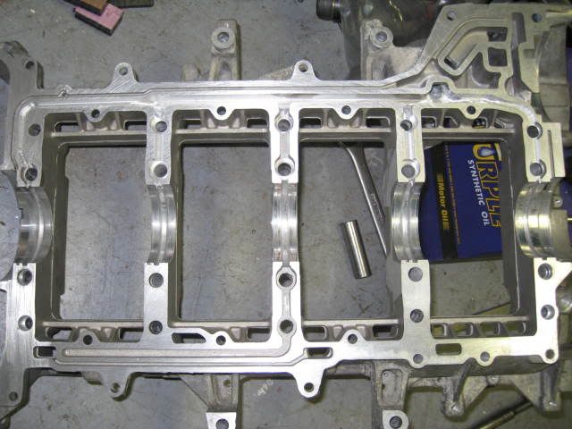
As a reference, here's a photo:
Specifically, here are the topics that I would be interested in hearing about, even if it's just speculation:
Minimizing flow restrictions. How to minimize the oil restriction before the oil makes it to the long channel that distributes oil to main bearings? I'm calling this spot "the well", its the round hole in the upper right corner of the photo that feeds the channel between the entrances to the mains #1 and #2.
The extent of restrictions. What's the pressure drop from the pump to "the well" without modifications? Has anyone measured the impact of modifications on this pressure drop?
Cavitation damage? Has anyone seen any signs of cavitation damage anywhere in the passages, before or after "the well?" Someone noted that there's some evidence of the girdle separating from the block near the oil passages. Is it possible that the violent energy release by collapsing cavitation bubbles is the cause of this damage?
How much will each main flow? Suppose that all mains are fed at equal pressure. How much more or less leakage there is at the thrust bearing #3 than there is at other mains? Is the clearance and thus the flow the same? Even though #3 doesn't feed rod bearings int he usual configuration? One could assume that the flow is proprotional to the cube of the radial clearance and proportional to the bearing diameter.
Static pressure at the main entrances. What the's oil flow speed in the distributing channel after the well at each of the entrances to the mains? I want to find out the static pressure that each of these entrances to the mains is seeing. If the oil is travelining much faster in the distributing channel at one of the main bearing entrances, that main bearing entrance is going to see a lower pressure.
Is the Taylor drilling necessary? Suppose that I can port the girdle in a way that it feeds mains #1, #2, #4, and #5 _exactly_ the same way. (I am not claiming I can, but humor me.) Would crank oil passages with a single main feeding each rod journal be enough then? In other words, would the Taylor drilling modification of feeding each rod journal from two mains be unnecessary in that case?
Measurements? Has anyone tried pumping oil thru any of this and actually measured the flow?
Cavitation II / oil-air separation? Does anyone understand how air separates from oil in these channels?
 10-01-2009, 02:49 PM
#2
Shameful Thread Killer
Rennlist Member
Rennlist Member
I can be of some help here as I've done some work on my GT engine. Note that all of this work is empirical without a shred of confirming pressure change or flow rate improvement. All work was done on both the girdle and the corresponding area of the block.
1 Casting flash cleaning. In the galleries where the oil drains back from the heads, there is a lot of flash(can be seen above in the upper and lower wall area). This flash will aireate the returning oil, and tend to keep it in a froth. Taking off the flash should allow it to run smoothly back into the pan.
2 Edge radiusing. Start at the area where the oil leaves the pump. You'll find a lot of sharp edges. Take your dremel or the angle die grinder and radius everything. I started with a die grinder, and a carbide cutter for the rough work, then worked down to an abrasive bit. Problem with the abrasive bits is that they get clogged with Al pretty quick. Work your way everywhere the oil goes except the mating surface of the girdle and the block, leave that alone. Work the areas to and from the filter and cooler lines too.
3 The second main via back from the pump has a restriction in the channel to limit the amount of oil that is forced into that journal. This might be one of the problems with the 2/6 journal oiling. I widened mine a bit to keep the oil up in that area.
4 I saw no cavitation damage. The fact that the oil is under pressure when it leaves the pump prolly accounts for this. Cavitation can only occur where there is the possibility of the fluid reaching it's vapor pressure. So, that's works against cavitation. You would need really high amounts of kinetic energy and a very sharp shear to achieve vapor pressure change in a pressurized fluid.
5. Cavitation II. I do understand(somewhat) how the fluids and the air interact in the drainback channels. fluid goes down, and air - or more accurately, byproducts of combustion go up to the head and out the vents. This is an important distinction. We all think of the crankcase air as being oil vapor. But tests done on aircraft engines, and other engines show that the vapor is made up primarily of the low VOCs and CO and NOx and even water vapor which are the products of combustion. We need to get that stuff out of the crankcase, and in the general scheme of things, it's rerouted back into the intake and used at a source of air to be run through again. Sadly, this is a result of emission rules, and it leaves a mess in the intakes of our engines, and deposits on the runners, and even the pistons.
When we mix in some of the oil which is in vapor suspension, it's a real problem to condense the oil, and return it to the case and yet allow the acidic combustion elements to escape to the atmosphere eventually. A true conundrum. What can help, is to limit the aeration of the oil as it returns to the sump.
I have no opinion of the flow rates at the various main journals. I also can't help with the Taylor drilling. I did no drilling on my block. I added the GTS baffle, and made sure the oil pump gears where still good. In hindsight, I should have replaced the oil pump, but it seems to be working well so far.
10-01-2009, 02:58 PM
#3
Race Director
Tuomo
It appears the bulk of oiling issues are centered at 2-6....I have never heard of oiling issues in any other bearing.....
With that said the upgrades I chose for the widow (track shark) did include slight massaging to the girdle oil passages (not sure exactly since I didn't do it, but was told a tiny bit) a taylor drilled crank among other things.... It does appear strokers that come with taylor-chevy drilling have less oilling issues than stock crank track driven 928's....but they tend to have vastly improved oiling systems too.....
10-01-2009, 04:28 PM
#4
Nordschleife Master
Minimizing flow restrictions. How to minimize the oil restriction before the oil makes it to the long channel that distributes oil to main bearings? I'm calling this spot "the well", its the round hole in the upper right corner of the photo that feeds the channel between the entrances to the mains #1 and #2.
Cavitation damage? Has anyone seen any signs of cavitation damage anywhere in the passages, before or after "the well?" Someone noted that there's some evidence of the girdle separating from the block near the oil passages. Is it possible that the violent energy release by collapsing cavitation bubbles is the cause of this damage?
I highly doubt that cavitation bubbles are the cause for this. If they were then the larger the passage, the more pronounced that it would be in theory.
How much will each main flow? Suppose that all mains are fed at equal pressure. How much more or less leakage there is at the thrust bearing #3 than there is at other mains? Is the clearance and thus the flow the same? Even though #3 doesn't feed rod bearings int he usual configuration? One could assume that the flow is proprotional to the cube of the radial clearance and proportional to the bearing diameter.
Static pressure at the main entrances. What the's oil flow speed in the distributing channel after the well at each of the entrances to the mains? I want to find out the static pressure that each of these entrances to the mains is seeing. If the oil is travelining much faster in the distributing channel at one of the main bearing entrances, that main bearing entrance is going to see a lower pressure.
Is the Taylor drilling necessary? Suppose that I can port the girdle in a way that it feeds mains #1, #2, #4, and #5 _exactly_ the same way. (I am not claiming I can, but humor me.) Would crank oil passages with a single main feeding each rod journal be enough then? In other words, would the Taylor drilling modification of feeding each rod journal from two mains be unnecessary in that case?
In the other thread you are refering to, there was a comment that increasing the flow in these passages would increas the flowrate into the heads further increasing the problem.
If one is to inspect the block you will see that the oil channels which supply oil to the heads are taken from 2 spots. When looking at the picture you linked to and you see the "well" the first pickup is just to the right (front of engine), of the well. Doing these mods will not increase the oil supply to the drivers side head in any way shape or form. The other side is taken off the rearward supply line which crosses over at the center main bridge. This area will again see no real increase in flow as the openings have only really been increased up until the bearings where the bearing channel which sits under the bearing shells will be the limiting orifice in the oil being supplied to that second side.
Plus the amount of oil let into the heads is determined by the tolerances of the parts such as cams, lifter buckets, etc. Or a built in restrictor. Like on the 87+ heads you can use a 944S2 valve to lower the oil flow into the heads.
I am curious on your comment Brian on the strokers having vastly improved oiling systems. What other modification do they get?
I will be like Doc cleaning up alot of the casting lines in the girdle. But I am going full drysump with an air/oil seperator pump and a larger resevior to eliminate picking up airated oil into the engine.
10-01-2009, 04:50 PM
#5
Shameful Thread Killer
Rennlist Member
Rennlist Member
I respectfully disagree with Colin on the cavitation comment. Cavitation can only occur where a liquid is in a position to change state from liquid to gas, and back again. The damage caused by this is the difference in energy as the medium changes states. A high pressure environment, even only slightly higher than ambient will prohibit cavitation from taking place. While there may be bubbles in the oil being pumped, this has nothing to do with cavitation, but is a natural byproduct of the design of the oil system.
For a historical perspective, Tucker learned this the hard way when he tried unsuccessfully to operate the valves of an engine by crankcase oil. It proved to be too compressible to be suitable to use for valve actuation. Ford also learned this the hard way when they relied on crankcase oil for the pressure product in their mechanical fuel injection on some trucks. Neither had anything to do with cavitation, but everything to do with aeration.
Dry sump oiling systems are designed to reduce the aeration with a fairly wide, flat catch can that has a lot of surface area, and is not very deep. Long narrow sumps aren't suitable, because the air remains entrained in the oil on it's circuit. Same concept to a wet sump, where the oil can spread out in the pan and some of the bubble can escape before being picked up. If the oil is regularly impacted by the throw of the crankshaft, that leads to serious air entrainment, and lots of bubbles in the oil circuit, thus leading to bearing lube starvation.
10-01-2009, 05:18 PM
#6
Nordschleife Master
Doc,
With the hydraulic systems that I had used and built for years, if our supply line to the pump was too small, or if the oil became a little frothed and got sucked into the pumps then we saw cavitation damage on the insides of the pumps. If continued to run this way then the damage would continue into the valvebanks, motors etc.
That is where my experiance and knowledge comes from on the cavitation front.
10-01-2009, 06:07 PM
#7
Nordschleife Master
The other problem is the supply to the bearings. That's a problem in the crank design. The girdles role in that is providing sufficient oil at a sufficient pressure. I don't believe that the girdle is restrictive to flow.
The information that is needed is what is the flow rate through each passage. One thing that is clear is the the area of the passages is much greater than the area of the bearing clearances. In fluid mechanics, the restrictions don't simply "add up," it's the largest restriction that dominates the flow rate.
I should go get some bearings out, but the holes in the bearings that fee the mains and then the rods are much smaller than the passages. Maybe those need to be hogged out to give more flow before worrying about the girdle.
I don't think those are limiting flow.
Everyone notices how they step down in size. This is because the further passages are flowing less and just don't need to be as big. Leaving the material makes them stronger.
If we knew the flow rate then the drop could be calculated. As I advocated above, I think the restrictions are at the bearing feed holes and, also, at the bearing clearances themselves.
This is a non-issue for oil. The air is not absorbed, it's entrained. And the vapor pressure of oil has got to be really low, like 0.01 bar. It's just not going to happen.
Lots more flows through 3 than the others as it's feeding a main and the heads with either 16 or 32 lifters. 1, 2 4 and 5 will all be the same as those feed a main and two rods.
This would be very interesting data.
If you want to run high RPMs for a long time I think it is. Preventing foam or air getting sucked into the engine is the first big step. No one has blown a rod bearing with a drilled crank and a dry sump.
No. (If so, they're not telling.)
Oil doesn't absorb air. Even water absorbs miniscule amounts, really. If the pick-up sucks foam or air, then there are problems. The air is bubbles caught in the liquid. It's not molecules absorbed into the oil itself.
So what am I doing to avoid my second 2/6 failure? I run an I-J windage system and will be doing oil analysis and checking the filter when I start tracking my 928 again. Why no drilled crank? No money and I think that the windage system will provide clean, or cleaner, oil to the pickup and I'm going to drive less aggressively/stupidly and keep RPMs down especially in corners.
Trending Topics
10-01-2009, 06:10 PM
#8
Nordschleife Master
Thread Starter
Some responses to Colin:
My (possibly incorrect) understanding of the cavitation phenomenon is different.
Assume no grossly aerated oil, but normal oil conditions. As Doc explained above, cavitation occurs when the static pressure in the fluid is low. Higher supply pressure reduces the likelihood of cavitation. How can cavitation then occur in the pressurized oil? If there is a local flow restriction that temporarily accelerates the oil to a high speed. At that point, the kinetic pressure rises and static pressure is reduced, possibly causing a cavitation bubble. Once the fluid slows down again, the cavitation bubble collapses, causing a reaction analogous to an explosion. This is a powerful reaction which can burn holes to steel and break oil.
It is in principle possible that the oil is accelerated at the turn to the mains and then slows down in the passage to main, causing cavitation damage. In practice, I don't know.
I don't have a crank or girdle in front of me. (I am at work, obviously not doing work. Acceptable since it's the after hours, in fact some would say preferrable to the bar downstairs.) I may be completely off base. However, it is my understanding that in stock configuration, the center main aka main #3 aka the thrust bearing does not feed any rod bearings. That's why the stock bearing doesn't have a groove.
Here's what Dennis Kao writes on his web page:
http://gallery.lasttenth.com/main.php?g2_itemId=1440
For a stock 928 crankshaft the:
1-5 rod journal is connected to the #1 main cross-drill.
2-6 rod journal is connected to the #2 main cross-drill.
3-7 rod journal is connected to the #4 main cross-drill.
4-8 rod journal is connected to the #5 main cross-drill.
The #3 main (center thrust bearing journal) has no cross -drill
Taylor leaves all of these existing oil passages in place but then adds a bunch more.
They add:
new cross-drills at #2, #3 and #4 mains
connect 1-5 rod journal to #2 main
connect 2-6 & 3-7 rod journals to #3 main
connect 4-8 rod journal to #4 main
If we assume equal flow from all main bearings, we can use the cross sectional area at each point to compute the speed. If the speed is equal, then the static pressure is equal. I think one should be able to make some educated guesses here.
I have never really understood this. I understand that there is some effort to push the oil inside the main journal center because of the 35mm main journal. However, since the rod is on an outer orbit, there will be a large force sucking in the oil. Net effect should be that it's always easier to push oil to the the rods bearings in the outer orbit at high rpm.
It's like a water tower. You don't need to ahve a monotonic path from a water tower to your faucet. All you need is the faucet to be lower than the water tower water level. Same thing when siphoning gas from a tank.
Now, it's possible that path zig-zagging between orbits is going to cause cavitation and/or air-oil separation, which is bad. But I find the basic centrifugal force argument in absence of cavitation/aeration to be logically incorrect.
Someone please educate me.
I think that we need to know more about the local static pressures int he fluid to be sure about this not being the problem. Which, as you say, is easier said than done.
The Porsche 928 cup car attempt used those for some, presumably good, reason.
""Cavitation damage? Has anyone seen any signs of cavitation damage anywhere in the passages, before or after "the well?" Someone noted that there's some evidence of the girdle separating from the block near the oil passages. Is it possible that the violent energy release by collapsing cavitation bubbles is the cause of this damage? ""
"Cavitation is much more present at much much higher pressures, think 3500+ PSI. It can happen at lower pressures, but is far less likely and does have a great deal to do with heat. I noted that there was indications of the lower girdle floating from excessive oil pressure. This was ONLY apparent around the oil channel passages. The larger the passage the LESS that was noted. The largest passage being to the center main showed very little.
I increased the size of this passage as well as the others to not only aid in providing more flow to each of the bearings. But also to help aleviate this "floating" of the girdle. I highly doubt that cavitation bubbles are the cause for this. If they were then the larger the passage, the more pronounced that it would be in theory."
Assume no grossly aerated oil, but normal oil conditions. As Doc explained above, cavitation occurs when the static pressure in the fluid is low. Higher supply pressure reduces the likelihood of cavitation. How can cavitation then occur in the pressurized oil? If there is a local flow restriction that temporarily accelerates the oil to a high speed. At that point, the kinetic pressure rises and static pressure is reduced, possibly causing a cavitation bubble. Once the fluid slows down again, the cavitation bubble collapses, causing a reaction analogous to an explosion. This is a powerful reaction which can burn holes to steel and break oil.
It is in principle possible that the oil is accelerated at the turn to the mains and then slows down in the passage to main, causing cavitation damage. In practice, I don't know.
""How much will each main flow? Suppose that all mains are fed at equal pressure. How much more or less leakage there is at the thrust bearing #3 than there is at other mains? Is the clearance and thus the flow the same? Even though #3 doesn't feed rod bearings in the usual configuration? One could assume that the flow is proprotional to the cube of the radial clearance and proportional to the bearing diameter.""
"Actually #3, being the center main, is the main bearing which feeds oil to the rod bearings. This is one reason that it had a larger passage than others from the factory."
"Actually #3, being the center main, is the main bearing which feeds oil to the rod bearings. This is one reason that it had a larger passage than others from the factory."
"The taylor drilled crank from the pictures that I have seen also allows the crank to get oil from the second bearing for the rods. I do plan on adding this to my crank, which will be able to utilize the greater amount of flow allowed to the #2 passage."
http://gallery.lasttenth.com/main.php?g2_itemId=1440
For a stock 928 crankshaft the:
1-5 rod journal is connected to the #1 main cross-drill.
2-6 rod journal is connected to the #2 main cross-drill.
3-7 rod journal is connected to the #4 main cross-drill.
4-8 rod journal is connected to the #5 main cross-drill.
The #3 main (center thrust bearing journal) has no cross -drill
Taylor leaves all of these existing oil passages in place but then adds a bunch more.
They add:
new cross-drills at #2, #3 and #4 mains
connect 1-5 rod journal to #2 main
connect 2-6 & 3-7 rod journals to #3 main
connect 4-8 rod journal to #4 main
""Static pressure at the main entrances. What the's oil flow speed in the distributing channel after the well at each of the entrances to the mains? I want to find out the static pressure that each of these entrances to the mains is seeing. If the oil is travelining much faster in the distributing channel at one of the main bearing entrances, that main bearing entrance is going to see a lower pressure."
"I believe that the pressure differentials at these pressures will be very minimal. Though this is an interesting line of thought that you have I highly doubt that anyone will have tested this. The reason being is that there are a ton of variables that one has to consider."
"I believe that the pressure differentials at these pressures will be very minimal. Though this is an interesting line of thought that you have I highly doubt that anyone will have tested this. The reason being is that there are a ton of variables that one has to consider."
""Is the Taylor drilling necessary? Suppose that I can port the girdle in a way that it feeds mains #1, #2, #4, and #5 _exactly_ the same way. (I am not claiming I can, but humor me.) Would crank oil passages with a single main feeding each rod journal be enough then? In other words, would the Taylor drilling modification of feeding each rod journal from two mains be unnecessary in that case?""
"The taylor drilling also prevents oil starvation from gravitational forces when spinning. If I was planning on spinning over 6200 RPM for extended periods of time then I would be getting the crank drilled for sure."
"The taylor drilling also prevents oil starvation from gravitational forces when spinning. If I was planning on spinning over 6200 RPM for extended periods of time then I would be getting the crank drilled for sure."
It's like a water tower. You don't need to ahve a monotonic path from a water tower to your faucet. All you need is the faucet to be lower than the water tower water level. Same thing when siphoning gas from a tank.
Now, it's possible that path zig-zagging between orbits is going to cause cavitation and/or air-oil separation, which is bad. But I find the basic centrifugal force argument in absence of cavitation/aeration to be logically incorrect.
Someone please educate me.
""Cavitation II / oil-air separation? Does anyone understand how air separates from oil in these channels?""
"It should not be able to. It should remain suspended in the oil until pushed out of the bearing areas and allowed to settle. The oil becomes airated from many things one of which is being whipped by the crank. Once the oil becomes too airated then the oil pump picks it up and that is when the damage occours."
"It should not be able to. It should remain suspended in the oil until pushed out of the bearing areas and allowed to settle. The oil becomes airated from many things one of which is being whipped by the crank. Once the oil becomes too airated then the oil pump picks it up and that is when the damage occours."
"Plus the amount of oil let into the heads is determined by the tolerances of the parts such as cams, lifter buckets, etc. Or a built in restrictor. Like on the 87+ heads you can use a 944S2 valve to lower the oil flow into the heads."
10-01-2009, 06:15 PM
#9
Shameful Thread Killer
Rennlist Member
Rennlist Member
You saw cavitation damage on the low side of the impellers on those pumps, which is what I've shared. Cavitation cannot happen unless there is a state change from liquid to gas. On the low side of the pump that is a high likelyhood, on the high side, it is not.
Using water as an example media, one could build a pump with a head of up to 10M or about 33Ft. At that point, the vapor pressure of water is reached and no matter how hard you suck, all you will get in the delivery line after the head of 33Ft is going to be water vapor. The same phenomenon is found in pump systems where the delivery line is bent, or as you've said too small to support the flow rates of the media, where the pressure head is reduced artificially. Bends, valves, wall surface tension all play a part in the pressure head on the low side, where cavitation can occur. Once the media passes the pump, the ability to have cavitation is very much reduced. You would need a media that has a low VP, low viscosity, and is a good thermal conductor - like fuel, which is the only media that I'm familiar with that commonly gets to it's vapor point after the pump. Oil in a crankcase would need to have a low pressure area, high flow rate, very sharp shear points, and very high heat. I don't think crankcase oil would reach it's VP in any situation like this.
The only fluids I've ever worked pumping have been Uranium-Hexaflouride in slurry reactors. We didn't worry much about cavitation there because it was an anhydrous environment, and the pressures were right on up there on the hot side. The heat exchange pressures of course demanded that the water vaporize, and we did have some cavitation issues on the condensate, but it was a balancing act that we finally got right by improving by supply lines to lower the effective pressure head at the inlets.
If you have some pitting, or scarring on the pressure side of the oil galleries, I'd like to investigate that, cause it sure sounds funny.
10-01-2009, 06:17 PM
#10
Nordschleife Master
Thread Starter
http://www.noria.com/learning_center...oup=Hydraulics
http://en.wikipedia.org/wiki/Cavitation
10-01-2009, 06:20 PM
#11
Shameful Thread Killer
Rennlist Member
Rennlist Member
If the oil moves slow, that's true. However, if one accelerates oil thru a restriction, the static pressure can get really low. This can cause vapor/vacuum bubbles in the air. If the restriction then eases and oil slows down again, the vapor bubbles explode (or should I say implode explosively).
10-01-2009, 06:33 PM
#12
Nordschleife Master
Thread Starter
I haven't seen pitting in the oil channels. My "cavitation I" point was simply a hypothesis in response to Colin seeing the block and the girdle being "separated" near the oil passages and near the oil passages alone.
Any situation in which the oil is accelerated and then slowed down again has the theoretical potential for cavitation damage. However, I agree with you that this would be unexpected on the pressure side of the oil system, unless there are obvious local restrictions. This was just one question / hypothesis on a long list.
Any situation in which the oil is accelerated and then slowed down again has the theoretical potential for cavitation damage. However, I agree with you that this would be unexpected on the pressure side of the oil system, unless there are obvious local restrictions. This was just one question / hypothesis on a long list.
You saw cavitation damage on the low side of the impellers on those pumps, which is what I've shared. Cavitation cannot happen unless there is a state change from liquid to gas. On the low side of the pump that is a high likelyhood, on the high side, it is not.
Using water as an example media, one could build a pump with a head of up to 10M or about 33Ft. At that point, the vapor pressure of water is reached and no matter how hard you suck, all you will get in the delivery line after the head of 33Ft is going to be water vapor. The same phenomenon is found in pump systems where the delivery line is bent, or as you've said too small to support the flow rates of the media, where the pressure head is reduced artificially. Bends, valves, wall surface tension all play a part in the pressure head on the low side, where cavitation can occur. Once the media passes the pump, the ability to have cavitation is very much reduced. You would need a media that has a low VP, low viscosity, and is a good thermal conductor - like fuel, which is the only media that I'm familiar with that commonly gets to it's vapor point after the pump. Oil in a crankcase would need to have a low pressure area, high flow rate, very sharp shear points, and very high heat. I don't think crankcase oil would reach it's VP in any situation like this.
The only fluids I've ever worked pumping have been Uranium-Hexaflouride in slurry reactors. We didn't worry much about cavitation there because it was an anhydrous environment, and the pressures were right on up there on the hot side. The heat exchange pressures of course demanded that the water vaporize, and we did have some cavitation issues on the condensate, but it was a balancing act that we finally got right by improving by supply lines to lower the effective pressure head at the inlets.
If you have some pitting, or scarring on the pressure side of the oil galleries, I'd like to investigate that, cause it sure sounds funny.
Using water as an example media, one could build a pump with a head of up to 10M or about 33Ft. At that point, the vapor pressure of water is reached and no matter how hard you suck, all you will get in the delivery line after the head of 33Ft is going to be water vapor. The same phenomenon is found in pump systems where the delivery line is bent, or as you've said too small to support the flow rates of the media, where the pressure head is reduced artificially. Bends, valves, wall surface tension all play a part in the pressure head on the low side, where cavitation can occur. Once the media passes the pump, the ability to have cavitation is very much reduced. You would need a media that has a low VP, low viscosity, and is a good thermal conductor - like fuel, which is the only media that I'm familiar with that commonly gets to it's vapor point after the pump. Oil in a crankcase would need to have a low pressure area, high flow rate, very sharp shear points, and very high heat. I don't think crankcase oil would reach it's VP in any situation like this.
The only fluids I've ever worked pumping have been Uranium-Hexaflouride in slurry reactors. We didn't worry much about cavitation there because it was an anhydrous environment, and the pressures were right on up there on the hot side. The heat exchange pressures of course demanded that the water vaporize, and we did have some cavitation issues on the condensate, but it was a balancing act that we finally got right by improving by supply lines to lower the effective pressure head at the inlets.
If you have some pitting, or scarring on the pressure side of the oil galleries, I'd like to investigate that, cause it sure sounds funny.
Last edited by ptuomov; 10-01-2009 at 06:51 PM.
10-01-2009, 06:37 PM
#13
Nordschleife Master
How's this: vapor pressure is 0.01 bar, maybe 0.001 bar. If the oil is pressurized to 3 or 5 bar (gauge), how fast does it need to flow to have the pressure drop that low? Considering that the oil shoots out into a 1 bar atmosphere, it just ain't happening in these engines.
Colin brought up sometime about air bubbles cavitating in pumps. That's a different application of the term from it's core meaning. A very similar effect, though, as the bubbles collapsing and expanding put mechanical forces on the pump and tubing walls.
10-01-2009, 06:41 PM
#14
Shameful Thread Killer
Rennlist Member
Rennlist Member
I haven't seen pitting in the oil channels. My "cavitation I" point was simply a hypothesis in response to collin seeing the blaock and the girdle being "separated" near the oil passages and near the oil passages alone.
Any situation in which the oil is accelerated and then slowed down again has the theoretical potential for cavitation damage. However, I agree with you that this would be unexpected on the pressure side of the oil system, unless there are obvious local restrictions. This was just one question / hypothesis on a long list.
Any situation in which the oil is accelerated and then slowed down again has the theoretical potential for cavitation damage. However, I agree with you that this would be unexpected on the pressure side of the oil system, unless there are obvious local restrictions. This was just one question / hypothesis on a long list.
"Cavitation is much more present at much much higher pressures, think 3500+ PSI. It can happen at lower pressures, "
Which is in direct contravention of everything in physics concerning cavitation. Perhaps you were talking about aeration? A completely different phenomenon, and has no bearing on cavitation.
<edit; crap, Glen beat me to it.>
10-01-2009, 06:42 PM
#15
Nordschleife Master
Thread Starter
But, as you said, it's probably not cavitating on the passages that lead to the bearings.
Oil-air separation can occur in the passages. How and where, I have no idea. Any guesses?