
Girdle oil passage modifications
 10-01-2009, 06:49 PM
#16
Nordschleife Master
Thread Starter
Right. Where's Bernoulli when I need him?
How's this: vapor pressure is 0.01 bar, maybe 0.001 bar. If the oil is pressurized to 3 or 5 bar (gauge), how fast does it need to flow to have the pressure drop that low? Considering that the oil shoots out into a 1 bar atmosphere, it just ain't happening in these engines.
Colin brought up sometime about air bubbles cavitating in pumps. That's a different application of the term from it's core meaning. A very similar effect, though, as the bubbles collapsing and expanding put mechanical forces on the pump and tubing walls.
Now, deaeration (is that even a word?) or aerated oil separating into air and oil and air being directed in one direction and oil being directed in another direction may be a problem. Anybody with any thoughts on this?
 10-01-2009, 07:03 PM
#17
Shameful Thread Killer
Rennlist Member
Rennlist Member
Sadly, this phenomenon is a fact of life in liquid oil lubed systems. You could design a separator but it would be bulky, and troublesome. The only thing you can do is insure you have enough mass volume to let the air naturally bubble out by gravity.
10-01-2009, 07:14 PM
#18
Nordschleife Master
My only thought is that that is an interesting thought: can the passages be re-worked to intentionally distribute the air equally to all bearings? It does seem that 2/6 gets more than it's share. When I tore down my trashed engine the 2 and 6 bearings were in the copper and the other 6 were fine.
10-01-2009, 07:25 PM
#19
Three Wheelin'
Join Date: Jun 2008
Location: Surprise, Arizona
Posts: 1,914
Likes: 0
Received 0 Likes
on
0 Posts
Because it is purely speculation, we don't know for sure air is actually the culprit in the failure of the 2/6 bearings. It seems to me that the only way to effectively gain more pressure to 2/6 is to very slightly restrict all the other passages. Do the guys that run an accusump still have 2/6 problems?
10-01-2009, 07:31 PM
#20
Nordschleife Master
Sorry guys after doing some checking I was backwards on that. You are correct on the cavitation front. 
The marring that I noted on the girdle and block did not have any pitting. It was simply from too high of a pressure pushing the two halves apart. Or at least that is how it appeared when I analyzed it.
I have seen the same symptoms on pumps rated for 3500PSI that have seen 5000PSI. The internal parts are fine, but the end plates show lifting and mild movement.
I figure with drysump and crank scraper I should be OK. With drilling the crank for just a little extra protection.
And Toumo I will have to go look at the crank and journals again to confirm which bearing supplies which. But you might be right in that the #3 is drilled to help aid getting the oil to the bearings as #2 doesnt have enough flow.
10-01-2009, 07:33 PM
#21
Nordschleife Master
Because it is purely speculation, we don't know for sure air is actually the culprit in the failure of the 2/6 bearings. It seems to me that the only way to effectively gain more pressure to 2/6 is to very slightly restrict all the other passages. Do the guys that run an accusump still have 2/6 problems?
10-01-2009, 07:58 PM
#22
Nordschleife Master
It's quite clear that air getting to the bearings contributes to the failure. I could go over the why's and how's but I'm going to leave that to you. There are many threads on this. Please use search.
10-01-2009, 09:35 PM
#23
Nordschleife Master
I think that the only verifiable fact in this thread that has been posted is that engines with the Taylor driling and Dry sumps have seen no failures....
I could be wrong but...... has anyone witha taylor drilled crank and a properly designed dry sump suffered rod ro main bearing failures???????? speak now or forever hold your peace....
I could be wrong but...... has anyone witha taylor drilled crank and a properly designed dry sump suffered rod ro main bearing failures???????? speak now or forever hold your peace....
10-01-2009, 09:52 PM
#24
Rennlist Member
Rennlist Site Sponsor

Quite a few years ago Porsche was having rod bearing failures on one of the flat-eight racing engines. They jacked the oil pressures higher and higher, but that didn't help. The analysis indicated a lack of oil in the rod bearings at high RPMs.
Eventually, they added a cap to feed oil into the crank from the end. (Power take-off was in the middle of the crank.) They were able to get the rod bearings to live at 18 psi, where they were failing at over 120 psi when the feed was into the mains.
The problem was forcing oil flow into the crank at the mains at high RPMs. This is likely one of the several reasons that the NASCAR engines use very small main journals.
10-01-2009, 09:53 PM
#25
Nordschleife Master
10-01-2009, 10:24 PM
#26
Nordschleife Master
Thread Starter
The intention was not to mispresent anything as a verifiable fact. Simply just asking for some advice on porting the girdle oil passages. Maybe a waste of the precious bandwidth.
10-01-2009, 11:30 PM
#27
Hey this is my .02 and I've posted this before, so pardon my redundancy but I hope this helps a little. All the oiling problems swirl around the 2/6 rod throw. I know some in racing have had other failures, but this could get into a million circumstances why, and face it...racing engines blow up some times.
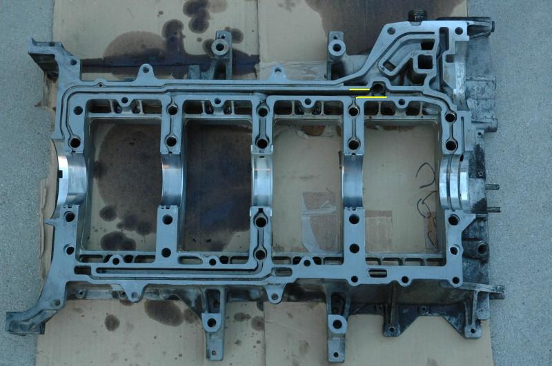
A few months ago it was posted on here (with pics) where someone radiused the holes feeding the number two main (and therefore rod throw). If I were going to open up these passages, I would only radius the edge on the side of the bedplate the oil was coming from, not the other side. That would let oil "skip by" easier if the trailing edge was done as well. I can post pics if my rambling isn't making sense. Any discussions circulating around oil pressure, sump design, etc. don't explain why the failures were isolated to the 2/6 journal and corresponding main.
It was also posted a while back that some racing outfit or whatever it was in Germany had done studies with plexiglass to watch the flow in the bedplate and stated the angle of oil entrance to the plate and its proximity to the #2 main feed where such that the oil was trying to arch around it instead of enter the hole.
I am led to believe the oiling improvements such as drilled crank, accusump, dry sump, etc. are valid help and good choices for any high performance motor, but again don't explain the 2/6 isolation.
If you'll recall, again I realize I've posted this before so pardon me if you've read it already and think I'm nuts, that I think the best fix is to drill a passage down the top of the main in the block and feed oil directly from the number one valley plug (which is in the way of your knock sensor). With a special made fitting that screwed in and had a tube that fit tight you could feed oil externally with a braided line directly to the 2/6 journal and not have to worry about compromising strength etc. in the mating surface between the block and girdle. I do agree also that smaller diameter bearings would require less volume to lubricate.
I think on street 928 engines it would benefit them to have a vacuum on the crankcase. It would make less wind around the crankshaft. Having a vacuum would also help remove combustion gases from the crankcase and therefore the oil. Combustion gases will combine with moisture in the oil to form a mild sulfuric acid solution that over time can degrade the lead lining in the bearings. Speaking of which, since these cars hold like 50 quarts of oil, they don't get the oil warm enough on short trips to remove the moisture. Having a vacuum would lower the boiling point of the water some and make it easier to withdraw from the crankcase. I remember an old bimmer I had in high school confused me when I first bought it because the motor would die instantly if the oil cap was removed. Then I discovered the crankcase hose on the valve cover was routed directly to the intake manifold without a pcv valve or restriction from the factory. Pretty slick they don't leak oil that way either when running.
10-02-2009, 01:26 AM
#29
Nordschleife Master
Thread Starter
A few months ago it was posted on here (with pics) where someone radiused the holes feeding the number two main (and therefore rod throw). If I were going to open up these passages, I would only radius the edge on the side of the bedplate the oil was coming from, not the other side. That would let oil "skip by" easier if the trailing edge was done as well. ... It was also posted a while back that some racing outfit or whatever it was in Germany had done studies with plexiglass to watch the flow in the bedplate and stated the angle of oil entrance to the plate and its proximity to the #2 main feed where such that the oil was trying to arch around it instead of enter the hole.
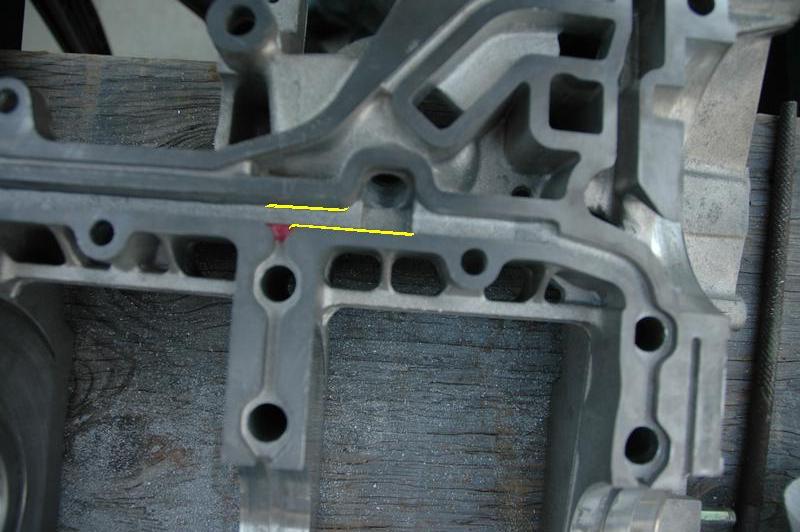
Assume that the oil is not aerated. A hypothesis: If one removes the right amount of material, then the static pressure is equalized between the entrances to the main #2 and the mains #1, #4, and #5. If the static pressure is equal, the "Taylor" drilling of the crank is unnecessary. $700 saved, hypothetically.
If the oil is aerated, all bets are off since I have no idea what causes the oil and air to split and go their separate ways. So windage trays, sump baffles, crank scrapers, drainage pipes from heads, etc. are still needed.
What do you think? If this works, the modification is relatively easy to turn into a product since the one can ship the girdle to someone who has the mod programmed in a cnc machine.
No, this is not a verifiable fact. It's an opinion, but with some logic behind it.
Last edited by ptuomov; 10-02-2009 at 01:53 AM.
10-02-2009, 09:58 AM
#30
Nordschleife Master
Thread Starter
A Japanese paper on crank drilling styles. They made a transparent crank and observed the oil flow:
http://www.tytlabs.co.jp/english/rev..._044suzuki.pdf
This is not 100% for the stock crank, but definitely relevant for the modern stroker cranks.
http://www.tytlabs.co.jp/english/rev..._044suzuki.pdf
This is not 100% for the stock crank, but definitely relevant for the modern stroker cranks.