
AC HVAC relay replacement - with pics
 04-27-2009, 03:31 AM
#1
Intermediate
Thread Starter
Join Date: Aug 2006
Location: Kennewick, WA
Posts: 47
Likes: 0
Received 0 Likes
on
0 Posts
Hi all,
I've been absorbing tons of info from this forum for the past coulple of years and would like to give a little back. For all of you are dreading the coming summer because you can't (or won't) afford the serious $$$ to troubleshoot your AC - here is a relatively simple fix that could return you to refrigeration-dom...fast and in less than $15.
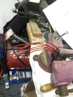
I own an an 87 S4 that recently lost its AC. This is kind of a problem in the desert of eastern Washington... So I was motivated. (note the background)

After some very educational search time on Rennlist I was able to quickly determine that the underpowered relay located in the HVAC control head had died. The relay was only designed to power about half of what the AC compressor draws, so its days were numbered from the start (don't ask me why Porsche allowed it) and it pretty widely recognized as a weak link in the system.
Anyhow.... in this case, replacement is not a very difficult thing if you are familiar with a soldering iron. The process has been covered so well by Dr. Bob and others on this forum that I wont post an exhaustive version - mainly just pics that add a little flavor to what's already been done.
The process goes like this:
1. Make sure that the relay is the culprit. the best writup on this is from Wally Plumley here https://www.928gt.com/t-wallyhvac.aspx unnder "TROUBLESHOOTING THE A/C COMPRESSOR CLUTCH ELECTRICAL SYSTEM"
2. Follow Dr. Bob's instructions here http://www.nichols.nu/Tempctrl.pdf
Another very helpful thread was this one: https://rennlist.com/forums/928-foru...freashing.html
3. Obtain from Radio Shack a 12v coil relay model 275-218 (10amp) it's significantly beefier than the original -- see pic
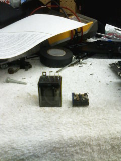
4. Desolder the non-functioning relay, using a soldering iron and a solder removal tool (vacuum bulb in the pic to the right of the unit worked fine, also from radio shack)
5. Solder about 7 inches of 18GA wire and some shrink tubing to each of the relay terminals according to Dr. Bob's instructions. there are 8 terminals, you will only be using 6 of them. It's a good idea to mark the side of the relay with a pen so you know whereeach wire will go....
6. Enlarge each of the empty holes in the circuit board using a drillbit that is just big enough to fit the 18 ga wire.
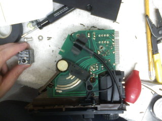
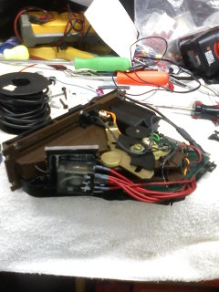
7. With the HVAC unit upside down, solder each of the wires to the correct hole with the relay resting off to the right of the HVAC head -- should look similar to this:
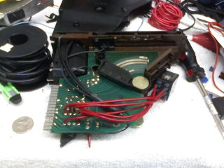
8. Attach the bottom half of the head unit casing - be gentle - notice how the wire will need to lay as flat as possible to get the unit closed. when you are satisfied, mount the relay to the side of the HVAC head along the vertical brown plastic wall (I used industrial strength velcro).
That's it. Put it back together and enjoy your return to cool! I hope this helps some of you out there.
Once again - many thanks to Dr. Bob, Wally, and Rennlist in general. I would not own my shark if this resource didn't exist.
Regards, Adrian
P.S. You may notice some extra fiber optic runs in my pics; don't panic...yours won't look like this ... I did some LED upgrades recently that required some creative work - I will also post some pics of this, but here is a sneek peek at the HVAC head.

I've been absorbing tons of info from this forum for the past coulple of years and would like to give a little back. For all of you are dreading the coming summer because you can't (or won't) afford the serious $$$ to troubleshoot your AC - here is a relatively simple fix that could return you to refrigeration-dom...fast and in less than $15.
I own an an 87 S4 that recently lost its AC. This is kind of a problem in the desert of eastern Washington... So I was motivated. (note the background)
After some very educational search time on Rennlist I was able to quickly determine that the underpowered relay located in the HVAC control head had died. The relay was only designed to power about half of what the AC compressor draws, so its days were numbered from the start (don't ask me why Porsche allowed it) and it pretty widely recognized as a weak link in the system.
Anyhow.... in this case, replacement is not a very difficult thing if you are familiar with a soldering iron. The process has been covered so well by Dr. Bob and others on this forum that I wont post an exhaustive version - mainly just pics that add a little flavor to what's already been done.
The process goes like this:
1. Make sure that the relay is the culprit. the best writup on this is from Wally Plumley here https://www.928gt.com/t-wallyhvac.aspx unnder "TROUBLESHOOTING THE A/C COMPRESSOR CLUTCH ELECTRICAL SYSTEM"
2. Follow Dr. Bob's instructions here http://www.nichols.nu/Tempctrl.pdf
Another very helpful thread was this one: https://rennlist.com/forums/928-foru...freashing.html
3. Obtain from Radio Shack a 12v coil relay model 275-218 (10amp) it's significantly beefier than the original -- see pic
4. Desolder the non-functioning relay, using a soldering iron and a solder removal tool (vacuum bulb in the pic to the right of the unit worked fine, also from radio shack)
5. Solder about 7 inches of 18GA wire and some shrink tubing to each of the relay terminals according to Dr. Bob's instructions. there are 8 terminals, you will only be using 6 of them. It's a good idea to mark the side of the relay with a pen so you know whereeach wire will go....
6. Enlarge each of the empty holes in the circuit board using a drillbit that is just big enough to fit the 18 ga wire.
7. With the HVAC unit upside down, solder each of the wires to the correct hole with the relay resting off to the right of the HVAC head -- should look similar to this:
8. Attach the bottom half of the head unit casing - be gentle - notice how the wire will need to lay as flat as possible to get the unit closed. when you are satisfied, mount the relay to the side of the HVAC head along the vertical brown plastic wall (I used industrial strength velcro).
That's it. Put it back together and enjoy your return to cool! I hope this helps some of you out there.
Once again - many thanks to Dr. Bob, Wally, and Rennlist in general. I would not own my shark if this resource didn't exist.
Regards, Adrian
P.S. You may notice some extra fiber optic runs in my pics; don't panic...yours won't look like this ... I did some LED upgrades recently that required some creative work - I will also post some pics of this, but here is a sneek peek at the HVAC head.
 04-27-2009, 12:14 PM
#2
Chronic Tool Dropper
Lifetime Rennlist
Member
Lifetime Rennlist
Member

Glad it worked for you! Great pictures too.
 04-27-2009, 01:30 PM
#5
Rennlist Member
very nice!
04-27-2009, 01:44 PM
#6
Owns the Streets
Needs Camber
Lifetime Rennlist
Member
Needs Camber
Lifetime Rennlist
Member
Cool.
Blue white and red. Is that the French flag.
Adrian M., is there a way to fix a broken fiber optic 'wires.'
I've got HVAC head with a broken glass wire to the temp adjustment ****.
I was thinking maybe using clear silicone RTV to re-attach it but don't think that will hold.
Hot glue gun? That's clear and has some bonding strength.
04-27-2009, 03:55 PM
#7
Intermediate
Thread Starter
Join Date: Aug 2006
Location: Kennewick, WA
Posts: 47
Likes: 0
Received 0 Likes
on
0 Posts
Hi Ernest,
Regarding the colors...my wife thinks it looks like the bomb-pops my daughter gets from the ice-cream man...
Regarding the optic lines, my experience is that anything disrupting the light path of the optic lines will diminish the intensity of the output. If I understand your situation right, I'd opt for replacing the fiber over repairing it for best results. You can by new optic lines here...
http://thefiberopticstore.com/FOS-mainpage.htm
With a little heat shrink and some injenuity you could completely restore those old lines. That's what I did and I'm pretty happy with the results.
That said, there's no harm in testing your repair method...if you're happy with the results, then you'd be back in business pretty quick.
For what it's worth...I'll be posting a semi formal write-up on the LED/optic conversion, if that helps.
Regards,
Adrian
Trending Topics
05-10-2009, 11:15 AM
#8
Addict
Rennlist Member
Rennlist Member
Join Date: Oct 2003
Location: Gone. On the Open Road
Posts: 16,421
Received 1,596 Likes
on
1,044 Posts
FYI: Anyone that doesn't have the confidence to go poking on the inside of the HVAC head can get a rebuilt unit from 928 International (core required.)
05-10-2009, 11:59 AM
#9
Owns the Streets
Needs Camber
Lifetime Rennlist
Member
Needs Camber
Lifetime Rennlist
Member
Hi Ernest,
Regarding the colors...my wife thinks it looks like the bomb-pops my daughter gets from the ice-cream man...
Regarding the optic lines, my experience is that anything disrupting the light path of the optic lines will diminish the intensity of the output. If I understand your situation right, I'd opt for replacing the fiber over repairing it for best results. You can by new optic lines here...
http://thefiberopticstore.com/FOS-mainpage.htm
With a little heat shrink and some injenuity you could completely restore those old lines. That's what I did and I'm pretty happy with the results.
That said, there's no harm in testing your repair method...if you're happy with the results, then you'd be back in business pretty quick.
For what it's worth...I'll be posting a semi formal write-up on the LED/optic conversion, if that helps.
Regards,
Adrian
Regarding the colors...my wife thinks it looks like the bomb-pops my daughter gets from the ice-cream man...
Regarding the optic lines, my experience is that anything disrupting the light path of the optic lines will diminish the intensity of the output. If I understand your situation right, I'd opt for replacing the fiber over repairing it for best results. You can by new optic lines here...
http://thefiberopticstore.com/FOS-mainpage.htm
With a little heat shrink and some injenuity you could completely restore those old lines. That's what I did and I'm pretty happy with the results.
That said, there's no harm in testing your repair method...if you're happy with the results, then you'd be back in business pretty quick.
For what it's worth...I'll be posting a semi formal write-up on the LED/optic conversion, if that helps.
Regards,
Adrian
Thanks Adrain.
Your hunch of repair light loss may be quite real.
The transition from broken fiber/silicone sealant/broken fiber with the raggedy break will scatter light. Plus you lose the internal light refraction/reflection that helps move the light along the fiber.
Don't think wrapping the light fiber joint with foil before it's shrinkwrapped will do much.
LED lighting will help bring the yellowing HVAC control head into the 2000's.
05-11-2009, 09:12 PM
#11
Shameful Thread Killer
Rennlist Member
Rennlist Member
I've done a few relay R&R. It can be ordered through 928sRUS as well. Also replace the fiber pipes, and the bulbs if needed.
