
My new OB / Racer in the making

 11-05-2013, 03:39 PM
#212
Rennlist Member
Your front spring rate influences the rear end handling and traction..and if you have enough up front, its way easy to have too much in the rear and that will make the rear end snap too much in transitions.
Soft & compliant sticks better than stiff and jerky.
Soft & compliant sticks better than stiff and jerky.
11-05-2013, 09:07 PM
#213
Race Director
Example, disconnecting the rear sway bar on my racer improved rear traction immensely...mostly since i think the stock rear bar was binding up....the improved rear traction really helped get on the power sooner in corners and didn't reduce traction from the front end like I thought it would......
11-12-2013, 01:38 AM
#214
Rennlist Member
Thread Starter
Out with the old,

In with the not so old.

Basically swapping out the '79 rear crossmember and swapping in an '82 to carry the '89 transaxle that will be installed shortly.
The difference is very subtle.
The '79 is on the bottom in this pic and has the extra pads cast into it.

In this pic the '79 is on the top. It appears that the mounting tabs are
a little longer, but didn't measure. Like I said, the differences seem pretty subtle in the two cross members. Definitely evolution, not revolution.

In with the not so old.
Basically swapping out the '79 rear crossmember and swapping in an '82 to carry the '89 transaxle that will be installed shortly.
The difference is very subtle.
The '79 is on the bottom in this pic and has the extra pads cast into it.
In this pic the '79 is on the top. It appears that the mounting tabs are
a little longer, but didn't measure. Like I said, the differences seem pretty subtle in the two cross members. Definitely evolution, not revolution.
11-12-2013, 02:03 AM
#215
Inventor
Rennlist Member
Rennlist Member
12-01-2013, 04:02 AM
#216
Rennlist Member
Thread Starter
Got the S4 tranny and later model torque tube in the car today. It was a one man show, me, the lift, the floor jack, the tranny jack, the webbing strap, and the come-along, and I needed them all.
The incredible floating drive train:

Lower control arm needed a little coaxing to fit back into its front mount. The come along was the big pursuader, the mallet was not doing the trick.

So nice to have it in, means I'll finally get to put the wheels back on and let my shop mates get their projects on the lift.

Edit to add pricing: '89 LSD 5 speed gear box $2500
'82 manual tranny X-member $ 150
'84 manual torque tube $ 400
The incredible floating drive train:
Lower control arm needed a little coaxing to fit back into its front mount. The come along was the big pursuader, the mallet was not doing the trick.
So nice to have it in, means I'll finally get to put the wheels back on and let my shop mates get their projects on the lift.
Edit to add pricing: '89 LSD 5 speed gear box $2500
'82 manual tranny X-member $ 150
'84 manual torque tube $ 400
Last edited by atb; 02-28-2014 at 02:05 PM.
04-14-2014, 01:51 AM
#218
Rennlist Member
Thread Starter
Been awhile since I posted on this thread. I've been busy with wiring (started new threads to post questions I had along the way), and am getting very close to being done. The wiring for my gauges will be the last wires that I need to feed through the firewall, and then I can drop the motor in.
It's almost been a joy to do wiring in an empty engine bay. I reconfigured the engine harness wiring so there is no 14 pin plug, and the engine harness that runs through the left side timing cover has been deleted in its entirety. The wires that remain from that harnes (bus 30, starter, and exciter circuit) now run behind the engine.
Before dropping in the motor, I'll finish tidying up under the dash, but the main thing is that all of the wires have been run to their destination points, and, with the exception of the engine sensors, are all hooked up.
So on the wiring front, I basically traced every circuit, and removed every one that I didn't need. That left me with lights, wipers, fans, fuel pump, horn, power socket, pod gauges, and power for the MS 3.57. The MS 3.57 has its own harness for all of the engine sensors (water temp, air temp, TPS, MAP, and knock), injectors, and O2.
That left me with the pile of wires, here's a partial shot:

No pod switches were retained (actually the pod cover itself is gone) no ignition switch, everything is on my center console:

In choosing where to mount my gauges (Oil Pressure, Oil Temp, Water Temp, Innovate AFR), I tried a few different locations, and came up with only two that seemed to make sense:


I decided on putting them above the center console. Having them infront of the pod seemed like information overload, and the AFR has a colored LED screen and would probably drive me nuts in my field of vision.
So, I started with two of these:

Made two of these (mirror images of each other)

Here's the first one in place:

And here's the rough in:

The pic doesn't really do it justice (having them temporarly held in place with blue tape doesn't help), but it will be a farily clean install. I plan on painting the shelves flat black to avoid glare.
Because I swapped from an OB MC to an S4, I still need to mount a brake light switch at the pedal, and I need to buy and wire in an accusump, but I'm definitely at the end of this long automotive wiring road. I learned a lot about 928 wiring along the way (can at least finally understand the WSM wiring diagrams anyhow).
It's almost been a joy to do wiring in an empty engine bay. I reconfigured the engine harness wiring so there is no 14 pin plug, and the engine harness that runs through the left side timing cover has been deleted in its entirety. The wires that remain from that harnes (bus 30, starter, and exciter circuit) now run behind the engine.
Before dropping in the motor, I'll finish tidying up under the dash, but the main thing is that all of the wires have been run to their destination points, and, with the exception of the engine sensors, are all hooked up.
So on the wiring front, I basically traced every circuit, and removed every one that I didn't need. That left me with lights, wipers, fans, fuel pump, horn, power socket, pod gauges, and power for the MS 3.57. The MS 3.57 has its own harness for all of the engine sensors (water temp, air temp, TPS, MAP, and knock), injectors, and O2.
That left me with the pile of wires, here's a partial shot:
No pod switches were retained (actually the pod cover itself is gone) no ignition switch, everything is on my center console:
In choosing where to mount my gauges (Oil Pressure, Oil Temp, Water Temp, Innovate AFR), I tried a few different locations, and came up with only two that seemed to make sense:
I decided on putting them above the center console. Having them infront of the pod seemed like information overload, and the AFR has a colored LED screen and would probably drive me nuts in my field of vision.
So, I started with two of these:
Made two of these (mirror images of each other)
Here's the first one in place:
And here's the rough in:
The pic doesn't really do it justice (having them temporarly held in place with blue tape doesn't help), but it will be a farily clean install. I plan on painting the shelves flat black to avoid glare.
Because I swapped from an OB MC to an S4, I still need to mount a brake light switch at the pedal, and I need to buy and wire in an accusump, but I'm definitely at the end of this long automotive wiring road. I learned a lot about 928 wiring along the way (can at least finally understand the WSM wiring diagrams anyhow).
05-26-2014, 07:45 PM
#219
Rennlist Member
Thread Starter
Accusump install in the cowl area.
Clamps mounted to a steel plate. The directions suggest doing this. I thought it was a good idea since otherwise the accusump mounts would actually be bolted to two different different pieces of sheetmetal, one side to the firewall and the other to the heater core block off plate.

I then clamped down the canister to the plate:

To mount the plate to the firewall, I used nylon spacers to create enough clearance for the mounting clamp bolt heads. (Here's three, fourth was already mounted - its captive under one of the brackets.)

Here's the canister in (hopefully) its final resting place. It's mounted at an angle. The acccusump instructions state to mount the oil side higher than the air side, so that air bubbles will tend to form at the output end of the canister. The idea is that the air bubbles will clear when priming the system at initial start up rather than trapped air being pushed out with the oil when you really need it when the EPS is activated under a pressure loss situation.

Took several tries to get this to fit. Clearance for the wiper motor and linkage crowded in from the right, and placement of the EDIS coil packs and module crowded from the left. In the end, got everything to fit. The only tight squeeze now is running the oil feed line. It is going to have to run under the wiper motor brace. Not a lot of room there. I was able to pound some more clearance with a hammer and pipe, and think I'll be able to run a -10AN line under there. Going to order up some line and fittings, after which I'll be able to mount the EPS valve and the pressure switch, and then finish wiring it all up.
Clamps mounted to a steel plate. The directions suggest doing this. I thought it was a good idea since otherwise the accusump mounts would actually be bolted to two different different pieces of sheetmetal, one side to the firewall and the other to the heater core block off plate.
I then clamped down the canister to the plate:
To mount the plate to the firewall, I used nylon spacers to create enough clearance for the mounting clamp bolt heads. (Here's three, fourth was already mounted - its captive under one of the brackets.)
Here's the canister in (hopefully) its final resting place. It's mounted at an angle. The acccusump instructions state to mount the oil side higher than the air side, so that air bubbles will tend to form at the output end of the canister. The idea is that the air bubbles will clear when priming the system at initial start up rather than trapped air being pushed out with the oil when you really need it when the EPS is activated under a pressure loss situation.
Took several tries to get this to fit. Clearance for the wiper motor and linkage crowded in from the right, and placement of the EDIS coil packs and module crowded from the left. In the end, got everything to fit. The only tight squeeze now is running the oil feed line. It is going to have to run under the wiper motor brace. Not a lot of room there. I was able to pound some more clearance with a hammer and pipe, and think I'll be able to run a -10AN line under there. Going to order up some line and fittings, after which I'll be able to mount the EPS valve and the pressure switch, and then finish wiring it all up.
02-26-2015, 04:53 PM
#220
Rennlist Member
Thread Starter
After months and months of wiring, I finally get to turn to the part of this project that I am looking forward to the most. The Engine.
I drove my S4 to the shop so the engine from that car can find its way into its new home in the track car. (The long term stroker project sitting on the work bench will find its way into the S4 one of these days.)
Out of the car:

And onto the stand:

This engine has always been a little bit of mystery. It has no engine number stamping on the casting block at the top of the “V”. The speculation has always been that it must be a warranty replacement block. This was confirmed when I removed the pan, and could plainly see that the crank girdle was held on by bolts, as was done with the later GTS engines (’93-’95), my S4 is an ‘88. Before ’93, the engines had studs with nuts holding the main journals together. Rob Edwards also noticed that the cradle had the factory clearancing in the cradle to make room for the longer stroke of the GTS crank.

Lastly, Tuomo suggested that I inspect the crank webbing for the circular ports that are unique to the GTS block. Bingo.

I'm hoping that this cross porting in the crank webbing will be helpful when combined with a vaccuum pump to help control windage.
I drove my S4 to the shop so the engine from that car can find its way into its new home in the track car. (The long term stroker project sitting on the work bench will find its way into the S4 one of these days.)
Out of the car:
And onto the stand:
This engine has always been a little bit of mystery. It has no engine number stamping on the casting block at the top of the “V”. The speculation has always been that it must be a warranty replacement block. This was confirmed when I removed the pan, and could plainly see that the crank girdle was held on by bolts, as was done with the later GTS engines (’93-’95), my S4 is an ‘88. Before ’93, the engines had studs with nuts holding the main journals together. Rob Edwards also noticed that the cradle had the factory clearancing in the cradle to make room for the longer stroke of the GTS crank.
Lastly, Tuomo suggested that I inspect the crank webbing for the circular ports that are unique to the GTS block. Bingo.
I'm hoping that this cross porting in the crank webbing will be helpful when combined with a vaccuum pump to help control windage.
Last edited by atb; 02-26-2015 at 06:21 PM.
02-26-2015, 04:55 PM
#221
Rennlist Member
Thread Starter
Because this is a track car, I want to do what I can to insure good oil control / management. I have an accusump installed to help with oil starvation, but doing some other proven mods as well.
Although there is some debate as to the utility of this mod, there are some that favor using the older oil pick up tube / sump baffle combination from the early 16v motors over the stock S4 system when it comes to track use.
The S4 sump has no baffling, and looks pretty much like the cleaned up ’79 pan below with all of the baffling removed.

The S4 pick up tube in the above picture has a built in screen, and rests very close to the bottom of the sump.
The earlier pan has this plastic “clover leaf” baffle bolted to the bottom of the sump, but it doesn’t sit flush on the bottom of the sump. It sits on top of the vanes cast into the pan, which allows oil to travel beneath it and get drawn up through the pick tube with sits in the middle.

The older draw tubes don’t have the built in screen like the later version. Instead, a screen closes off the sump section of the pan. You can also see that I had to elongate the dipstick tube hole, as the S4 dipstick is positioned slightly rearward of the older models.

Here’s a close up of that mod, and which also requires a slight bend to be made in the dipstick.

Although there is some debate as to the utility of this mod, there are some that favor using the older oil pick up tube / sump baffle combination from the early 16v motors over the stock S4 system when it comes to track use.
The S4 sump has no baffling, and looks pretty much like the cleaned up ’79 pan below with all of the baffling removed.
The S4 pick up tube in the above picture has a built in screen, and rests very close to the bottom of the sump.
The earlier pan has this plastic “clover leaf” baffle bolted to the bottom of the sump, but it doesn’t sit flush on the bottom of the sump. It sits on top of the vanes cast into the pan, which allows oil to travel beneath it and get drawn up through the pick tube with sits in the middle.

The older draw tubes don’t have the built in screen like the later version. Instead, a screen closes off the sump section of the pan. You can also see that I had to elongate the dipstick tube hole, as the S4 dipstick is positioned slightly rearward of the older models.

Here’s a close up of that mod, and which also requires a slight bend to be made in the dipstick.
Last edited by atb; 02-26-2015 at 06:23 PM.
02-26-2015, 04:57 PM
#222
Rennlist Member
Thread Starter
To help with windage control, I installed a 3/8” pan spacer. This one was sourced from Mike Simard. The idea originally came from Louis Ott in an attempt to get the pooled oil returning to the sump as far away from the spinning crank as possible to reduce oil aeration from windage. The 3/8” was determined as the maximum space that could be created before the pan hit the crossmember.
After a lot of internal debate, I decided that I would use Loctite 574 between the spacer and the bottom of the block. These are two machined surfaces, and I don’t really see a need to be removing the spacer anytime soon. I bolted it together, cleaned up the excess, and let is set up for about 4 days.


Because of the pan spacer, the pick up tube also has be lowered to maintain its relationship with the sump baffle.
Simard provided an extender for the main tube, but it required that the stock ’79 tube be cut down about a �”.

No spacers were provided for the pick up tube supports, but I found these chrome ones at the local hardware store. You can see the main spacer where the tube goes into the block.

Did not get a pic of the spring loaded rubber snorkel that goes on the end of the pick up tube before I closed it up. I didn’t use any pan gasket, but applied Permatex Motoseal to both surfaces and let it set up for a minute, then bolted it together.

I’m hoping that these mods, together with the accusump, and a crank vacuum pump, will keep my engine safe from oil starvation.
Time to flip the motor over and start working on the top side.
After a lot of internal debate, I decided that I would use Loctite 574 between the spacer and the bottom of the block. These are two machined surfaces, and I don’t really see a need to be removing the spacer anytime soon. I bolted it together, cleaned up the excess, and let is set up for about 4 days.
Because of the pan spacer, the pick up tube also has be lowered to maintain its relationship with the sump baffle.
Simard provided an extender for the main tube, but it required that the stock ’79 tube be cut down about a �”.
No spacers were provided for the pick up tube supports, but I found these chrome ones at the local hardware store. You can see the main spacer where the tube goes into the block.
Did not get a pic of the spring loaded rubber snorkel that goes on the end of the pick up tube before I closed it up. I didn’t use any pan gasket, but applied Permatex Motoseal to both surfaces and let it set up for a minute, then bolted it together.
I’m hoping that these mods, together with the accusump, and a crank vacuum pump, will keep my engine safe from oil starvation.
Time to flip the motor over and start working on the top side.
Last edited by atb; 02-26-2015 at 06:24 PM.
03-09-2015, 03:42 PM
#223
Rennlist Member
Thread Starter
Working topside on the engine starting with the intake manifold.
I'm running Megasquirt 3.57 on this motor, which uses the GM throttle position switch.
Here's the stock unit in place.

Here's the GM unit. Because the throttle plate axle is shaped like a "D", the TPS is clocked at an odd angle. The plug end is actually contacting the intake and the pig tail is facing the wrong way - running under the plenum, not out the back.

Also, the axle is too long ( the Bosch unit has a deeper cavity than the GM ) so the GM does not sit flush on the throttle body casting.
So, we pull out the trusty dremel and make some mods. ( The stock TPS will still work with the mods should this TB find its way back onto an LH car later in life.)
Shorten the axle.

Now it sits flush against the TB, but looks like I’ll need some spacers under the mounting ears.

Cut another flat in the back of the “D” so I could clock the TPS 180 degrees.


Fabricated the adapter plate to mount the GM TPS to. This is just a working copy. I’ll make a cleaner version once all of the measurements are dialed in.

All done!

TPS is functioning, but I’ll have to double check if its within spec for the MS 3.57. The GM has a longer throw than the Bosch, so I don’t get maximum resistance. It will top out at 4.6 k when twisted all the way.


I'm running Megasquirt 3.57 on this motor, which uses the GM throttle position switch.
Here's the stock unit in place.
Here's the GM unit. Because the throttle plate axle is shaped like a "D", the TPS is clocked at an odd angle. The plug end is actually contacting the intake and the pig tail is facing the wrong way - running under the plenum, not out the back.
Also, the axle is too long ( the Bosch unit has a deeper cavity than the GM ) so the GM does not sit flush on the throttle body casting.
So, we pull out the trusty dremel and make some mods. ( The stock TPS will still work with the mods should this TB find its way back onto an LH car later in life.)
Shorten the axle.
Now it sits flush against the TB, but looks like I’ll need some spacers under the mounting ears.
Cut another flat in the back of the “D” so I could clock the TPS 180 degrees.
Fabricated the adapter plate to mount the GM TPS to. This is just a working copy. I’ll make a cleaner version once all of the measurements are dialed in.
All done!
TPS is functioning, but I’ll have to double check if its within spec for the MS 3.57. The GM has a longer throw than the Bosch, so I don’t get maximum resistance. It will top out at 4.6 k when twisted all the way.
 08-03-2015, 11:11 AM
#225
Rennlist Member
Thread Starter
Lots of small time consuming projects as of late.( posted in separate threads).
I replaced to steering column bearing. Nice to have all the slop taken out, feels much more precise.
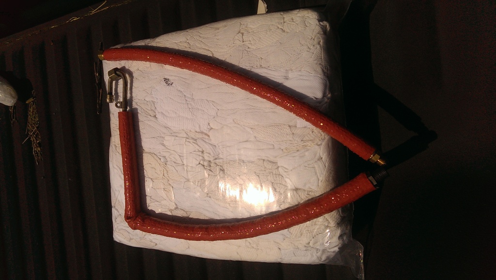
The major thing holding me back on the engine install was what do about fuel lines. The OB has flexible fuel lines that run from the fire wall to the CIS hard lines at the side of the engine. The S4 has hard lines that come under the car, and the bolt to combination hard/soft lines in the engine compartment, one to pressure dampener at the front of the engine, the other to the fuel cooler at the back of the engine. I did not want to have to use S4 fuel lines as they run all the to the back of the car and it would be a major operation. I bought several GB replacement fuel lines because they all needed replacement, and it turned out one had the critical adapter which allowed me to fabricate the remaining fuel lines using the stock hardware.
I installed 36lb injectors in anticipation of things to come. The MS 3.57 should be able to control them without any issues.
I had my MS box built with the knock sensor board , so I'll be running the stock knock sensors. I fabbed a custom mount which runs the knock sensor leads behind the throttle quadrant on the intake plenum.
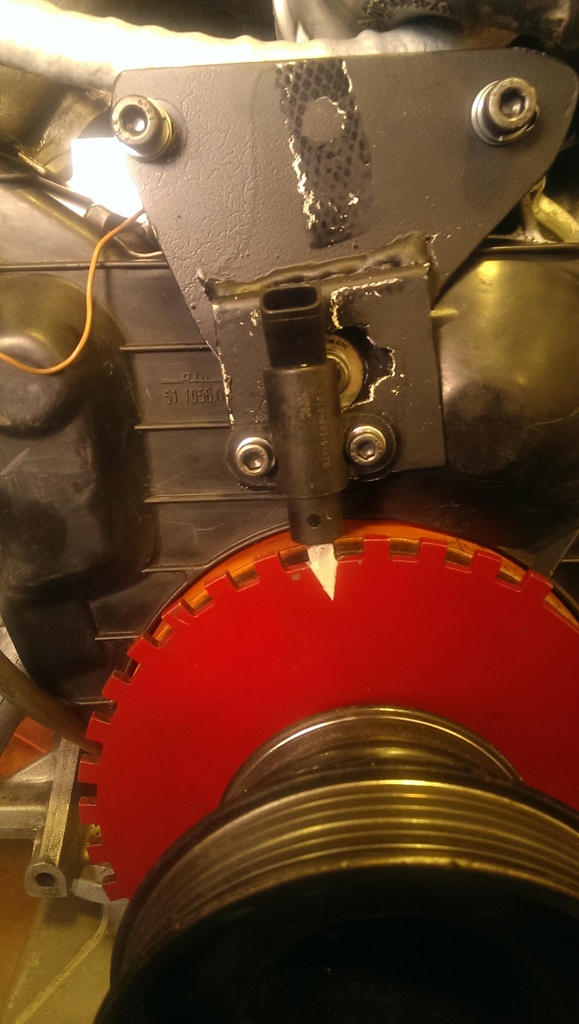
I'm running the Ford EDIS ignition system which uses a VR sensor over a 16-1 crank wheel. I had to fab a mount for the sensor.
 [
[
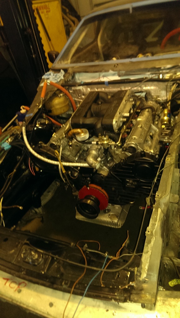
Finally, engine installed!
With the engine in, I was able to install the flywheel and double disk clutch from the '79 engine. Supposedly lighter and with more holding power than the stock S4 single disk unit.
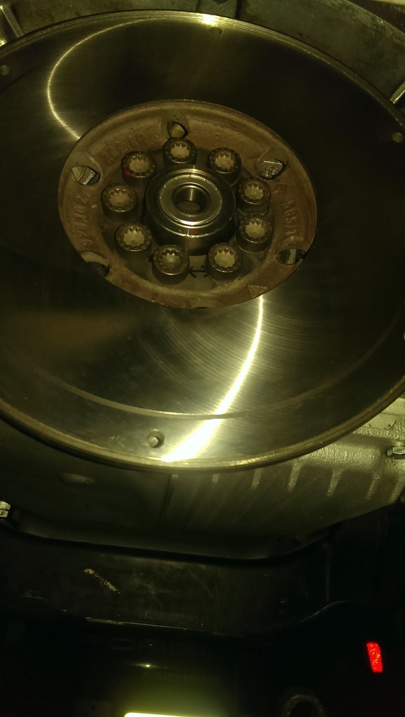
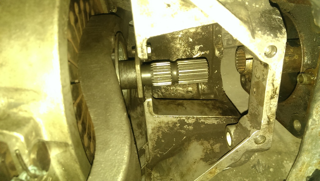
During that process it became apparent that the front TT bearing had migrated, so the TT is going to need a rebuild before I can track the car. You can see it right behind the pinch collar.
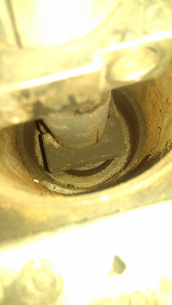
Installed lower bell housing, installed starter and slave. With the clutch in I can now see if those brake lines I fabricated hold pressure.
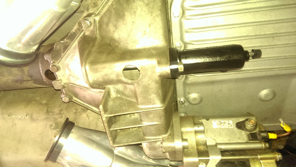
More updates soon. Exhaust, shift linkage, engine accessories, wire up engine, fill with fluids.
Getting closer!
I replaced to steering column bearing. Nice to have all the slop taken out, feels much more precise.
The major thing holding me back on the engine install was what do about fuel lines. The OB has flexible fuel lines that run from the fire wall to the CIS hard lines at the side of the engine. The S4 has hard lines that come under the car, and the bolt to combination hard/soft lines in the engine compartment, one to pressure dampener at the front of the engine, the other to the fuel cooler at the back of the engine. I did not want to have to use S4 fuel lines as they run all the to the back of the car and it would be a major operation. I bought several GB replacement fuel lines because they all needed replacement, and it turned out one had the critical adapter which allowed me to fabricate the remaining fuel lines using the stock hardware.
I installed 36lb injectors in anticipation of things to come. The MS 3.57 should be able to control them without any issues.
I had my MS box built with the knock sensor board , so I'll be running the stock knock sensors. I fabbed a custom mount which runs the knock sensor leads behind the throttle quadrant on the intake plenum.
I'm running the Ford EDIS ignition system which uses a VR sensor over a 16-1 crank wheel. I had to fab a mount for the sensor.
[Finally, engine installed!
With the engine in, I was able to install the flywheel and double disk clutch from the '79 engine. Supposedly lighter and with more holding power than the stock S4 single disk unit.
During that process it became apparent that the front TT bearing had migrated, so the TT is going to need a rebuild before I can track the car. You can see it right behind the pinch collar.
Installed lower bell housing, installed starter and slave. With the clutch in I can now see if those brake lines I fabricated hold pressure.
More updates soon. Exhaust, shift linkage, engine accessories, wire up engine, fill with fluids.
Getting closer!