
Documenting a ground up engine build
 04-06-2009, 12:50 PM
#1
Rennlist Member
Thread Starter

So, I'm building a new 4.5l motor for my convetable and I thought I would try to document the process ala Dwane. Lots of this stuff is just out of the WSM, but there is some practical stuff and some updates that might be interesting.
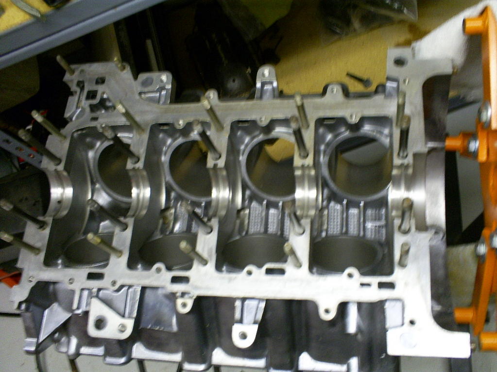
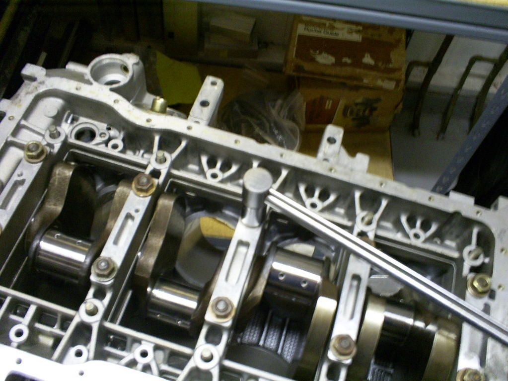
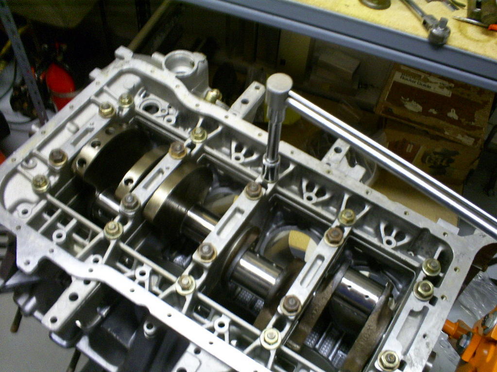
I am starting out with a brand new block. (snagged off ebay for a song) For the first part of the build I am going to have the Girdle off, and so there will only be two motor mounting points present, but I wanted to have it on the engine stand. So we fabricated the special tool below (900.002.004) as a prop between the bottom section of the motor stand and the valley of the V. Worked out pretty well.

I am starting out with a brand new block. (snagged off ebay for a song) For the first part of the build I am going to have the Girdle off, and so there will only be two motor mounting points present, but I wanted to have it on the engine stand. So we fabricated the special tool below (900.002.004) as a prop between the bottom section of the motor stand and the valley of the V. Worked out pretty well.
 04-06-2009, 12:57 PM
#3
Rennlist Member
Thread Starter
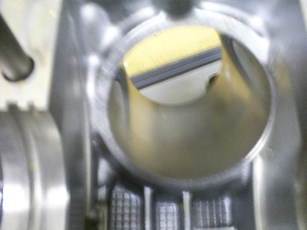
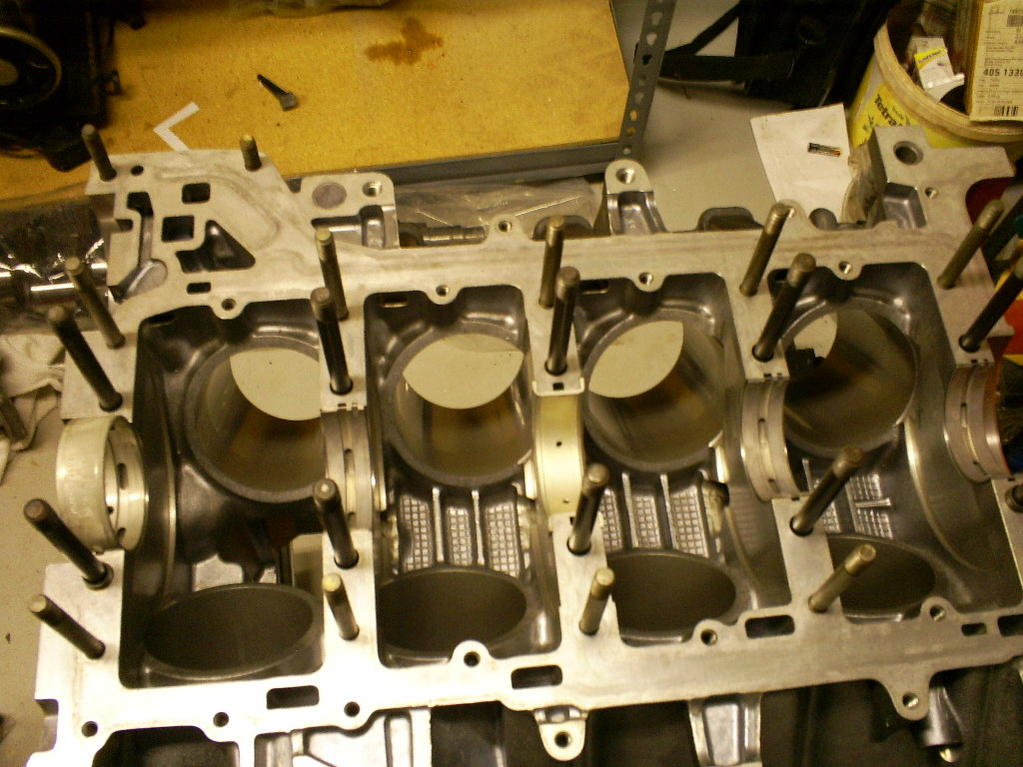
Here is a shot of a factory new bore. I was surprised that the famious polish on the alumasil does not go all the way to the bottom of the bore, it stops about 2 inches from the bottom. Sorry about the picture quality.
This block had never been run, but it had been put together and sealed. I wanted to remove the old sealent before I put the new stuff on. A razor blade took about 80% of it off, but there was still a thin layer on there. I found that hitting the remainly layer lightly with a 600 grit sand paper would cause it to pill up and then the rest would come up easily with the razor.
This block had never been run, but it had been put together and sealed. I wanted to remove the old sealent before I put the new stuff on. A razor blade took about 80% of it off, but there was still a thin layer on there. I found that hitting the remainly layer lightly with a 600 grit sand paper would cause it to pill up and then the rest would come up easily with the razor.
04-06-2009, 01:08 PM
#4
Rennlist Member
Thread Starter
This is Honolulu. Everyone's toes hang out. Those are actually my Dad's who is 84 and pretty senile, but still knows a lot and a big help.
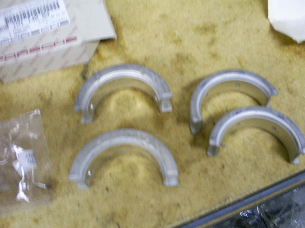
I had some drama about main bearings. My motor was a '79 and my new case has no serial numbers at all (strange). So I go '79 bearings, but the case seems to be an '82 vintage so the front main would not work. D.R. had a set of 5l mains on overstock and the front is the same, so I picked that up. Here is a summary of the main bearing differences.
The fronts. I think that there is just 79-82 and then 82 and beyond are the circular. I was happy to go with the circulars anyhow because my old mains looked pretty new except there was a lot of wear on the front and the thrust surface.
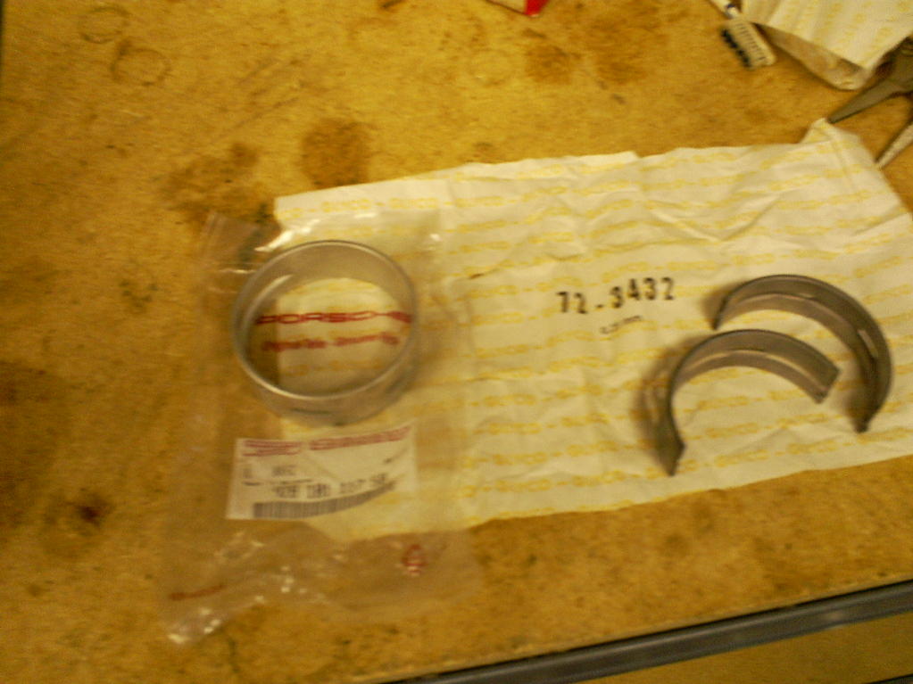
Number 2,4 and 5. The later style only has oil feed on one side. They would have worked in my block, I think, and I suspect they are an improvement, but I chickened out and put the stock style for the block in.
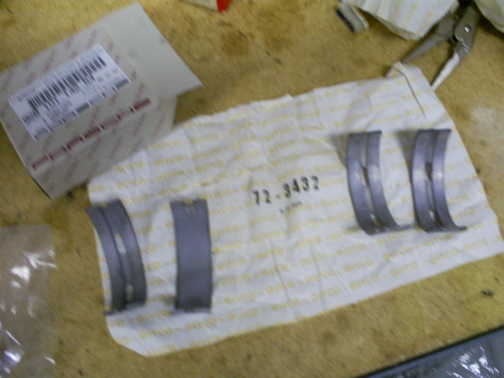
The thrusts. The larger thrust surface on the later style is very easy to see. The later ones would not work with my '79 crank as it is not cut away for this large of a thrust surface.
I had some drama about main bearings. My motor was a '79 and my new case has no serial numbers at all (strange). So I go '79 bearings, but the case seems to be an '82 vintage so the front main would not work. D.R. had a set of 5l mains on overstock and the front is the same, so I picked that up. Here is a summary of the main bearing differences.
The fronts. I think that there is just 79-82 and then 82 and beyond are the circular. I was happy to go with the circulars anyhow because my old mains looked pretty new except there was a lot of wear on the front and the thrust surface.
Number 2,4 and 5. The later style only has oil feed on one side. They would have worked in my block, I think, and I suspect they are an improvement, but I chickened out and put the stock style for the block in.
The thrusts. The larger thrust surface on the later style is very easy to see. The later ones would not work with my '79 crank as it is not cut away for this large of a thrust surface.
04-06-2009, 01:40 PM
#5
Nordschleife Master
Does your camera, or lens have a macro mode? Should have a picture of a small flower next to it. Your photos are fuzzy because you're closer than the minimum focal length of the lens in its default wideangle distance.
Great topic for documenting - this is a topic I'd love to learn more about, as I intend to have a go at it eventually.
Great topic for documenting - this is a topic I'd love to learn more about, as I intend to have a go at it eventually.
04-06-2009, 04:00 PM
#7
Rennlist Member
Thread Starter
Sorry about the picture quality. Looked good on the camera, but obviously not. Just going to have to live with it for the next few posts, cause the longblock is already together and I am not really feeling like taking it back apart for better pics.
Trending Topics
04-06-2009, 04:08 PM
#8
Rennlist Member
Thread Starter
I did some clean up of the flash on the Girdle, in the area arount the outlet of the oil pump, per Dr Bob's suggestion.
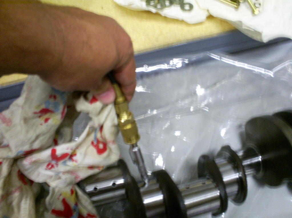
I had the crank taken down 0.25mm on the mains and just polished on the rods.
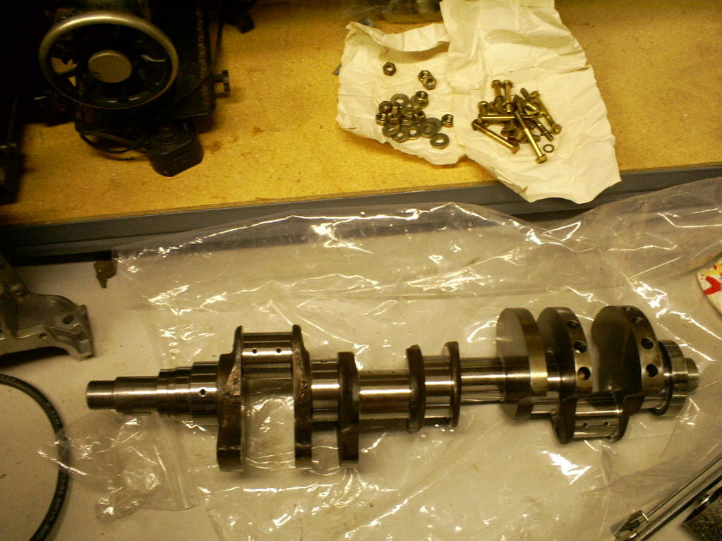
Blowing out the crank oil passages. They were very clean and I didn't get anything out at all, but bettwer the be safe...
I had the crank taken down 0.25mm on the mains and just polished on the rods.
Blowing out the crank oil passages. They were very clean and I didn't get anything out at all, but bettwer the be safe...
04-06-2009, 04:13 PM
#9
Rennlist Member
Thread Starter
Mains, set in place, I did a dry fit with some plastigage to make sure the bearing fit came out. Nobody tells you how much if a pain it is to get the smashed plasitgage back off the bearings afterwards. I decided to skip that step on the rods just because of the cleanup.
04-06-2009, 04:22 PM
#11
Rennlist Member
Thread Starter
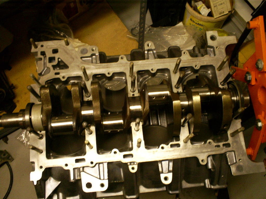
Crank set into the mains with front and rear main seals. The seals went in easily with no special tools, but the getting the front main bearing on its pin was a major pain. Figure about an hour of pulling the crank up, trying to get the bearing aligned on the pin, and having the whole assembly slip and wedge in place. The trick in my case was to give up and decide to go for lunch. Went right in then. Also I put a scratch on the front edge of the bearing at the center of the hole and noted carefully how the front edge of the bearing should line up with the case. Assembly lube on the bearings and thrust surfaces. For some reason, as I was messing with the front bearing, the thrust kept walking out of position, but it was pretty easy to get it back into position afterwards by lifting very slightly on the rear of the crank and pressing on the side of the bearing.
04-06-2009, 04:33 PM
#12
Rennlist Member
Thread Starter
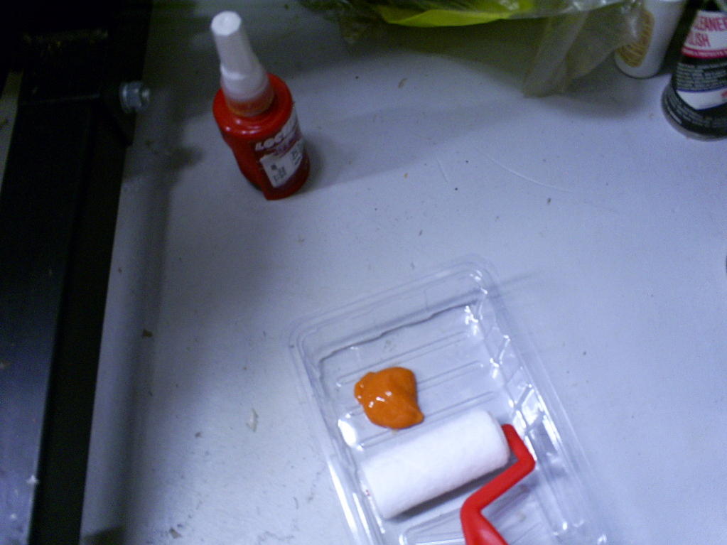
Loctite 574 and roller. I could not find any parts houses anywhere in the state that had it so I had to go to the dealer (gasp!). They stock it for their own use and will sell it. It was about $50. Knowing the dealer, that means it would be about $10 anywhere else, but I have a 911 motor to put together too and I will use some for that so I don't feel too bad. The roller was $3 and home depot.
I was suprised in that I was expecting a liquid and the acutal consistency is more like pudding. I used about a tablespoon , which I think is about 1/3 to 1/2 of the bottle.
This picture is pretty worthless because if the clarity, but this is the girdle with the bearings in, assembly lube, and the loctite rolled on.
04-06-2009, 04:42 PM
#13
Rennlist Member
Thread Starter
The girdle in place, and torquing the 19mm nuts. After the nuts are set in place, but before they are torqued you have to put the oil pump in place as it helps to set the alighment between the case halves. Torquing is in four steps in the usual X pattern.
Torquing the 17mm nuts. Getting old. Three steps here. Then two steps for the 13mms. Sheesh. They were not shy about the fastners here.
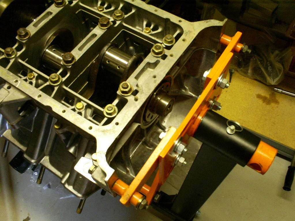
With the girdle in place the other two bolts on the engine stand can be put in place and special tool 900.002.004 can be retired. Getting ready to flip.
Torquing the 17mm nuts. Getting old. Three steps here. Then two steps for the 13mms. Sheesh. They were not shy about the fastners here.
With the girdle in place the other two bolts on the engine stand can be put in place and special tool 900.002.004 can be retired. Getting ready to flip.
04-06-2009, 04:57 PM
#15
Rennlist Member
Thread Starter
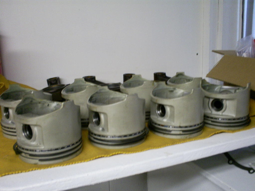
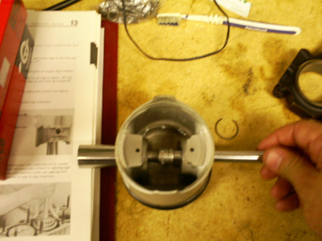
New pistons and rings (yay!). I am opting for the concave, low compression pistons because I am going to boost.
Driving out a wrist pin to put the rod on the piston. The rods have to go with the wide side towards the crank and the narrow side toward the other rod on the journal. The clips on the pins are easy to pop out but a bit of a pain to get back in. I ended up filing a little notch near one side of the tip of the blade of a screwdriver to hold the clip while i pressed it into position. Worked OK, but still a pain. Plus my assembly lube is about the color of blood, so when your slice yourself its hard to know what you have to clean up.
Assembly lube on the rod bearings, tubes put over the threads of the rod studs to protect the cylinder walls and crank during installation. New nuts.
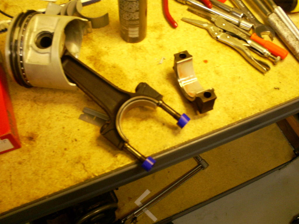