
'87 HVAC Vacuum Leak Testing and Repair Procedure w/pics
 02-27-2009, 10:16 AM
#16
Rennlist Member
Dwayne, you are the man. It is a little creepy that each job that I am planning to do is being fully documented by you right before I get ready to start it. Have you been spying on my car? If you have, keep up the good work. I can keep the light on and the garage unlocked if it helps.
I can't tell you how much easier your hard work has made these jobs for me. The quality of your documentation is unbelievable.
Thanks again.
I can't tell you how much easier your hard work has made these jobs for me. The quality of your documentation is unbelievable.
Thanks again.
 02-28-2009, 12:20 AM
#17
Rennlist Member
Thread Starter
Join Date: Sep 2007
Location: Ridgecrest, California
Posts: 1,363
Likes: 0
Received 143 Likes
on
28 Posts
Next, connect the passenger window switch wiring lead to the wiring harness.
Connect the rear wiper switch wiring lead to the wiring harness. If you have a sunroof, connect it's wiring lead to the harness at this time.
On the driver's side, route the driver's window switch wiring lead behind the central locking module.
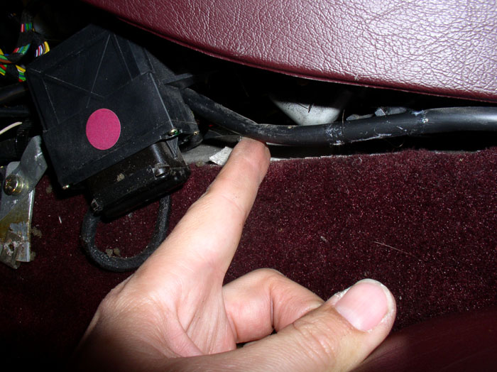
Then connect the window switch wiring lead to the wiring harness as shown.
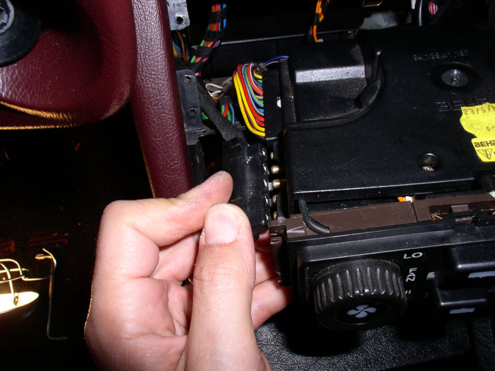
Next, connect the A/C switch harness plug to the back of the A/C switch on the central warning strip as shown.
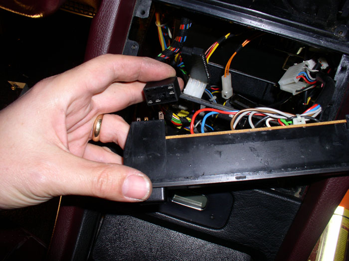
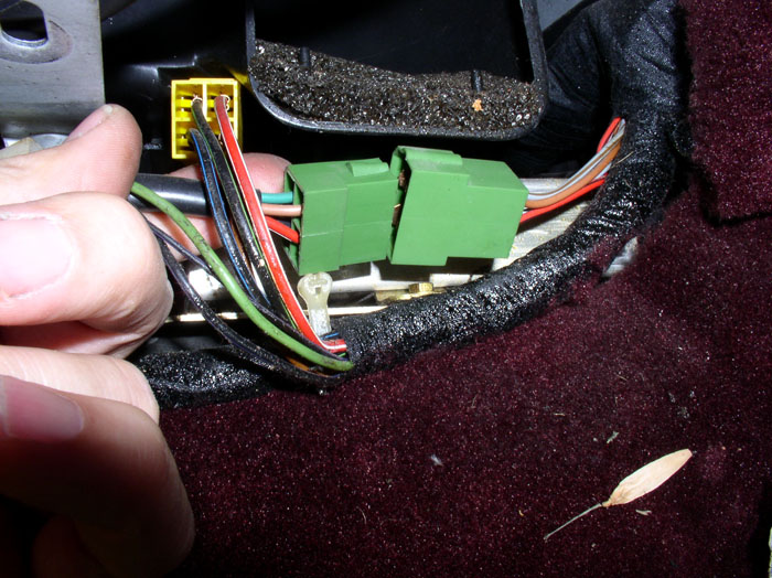
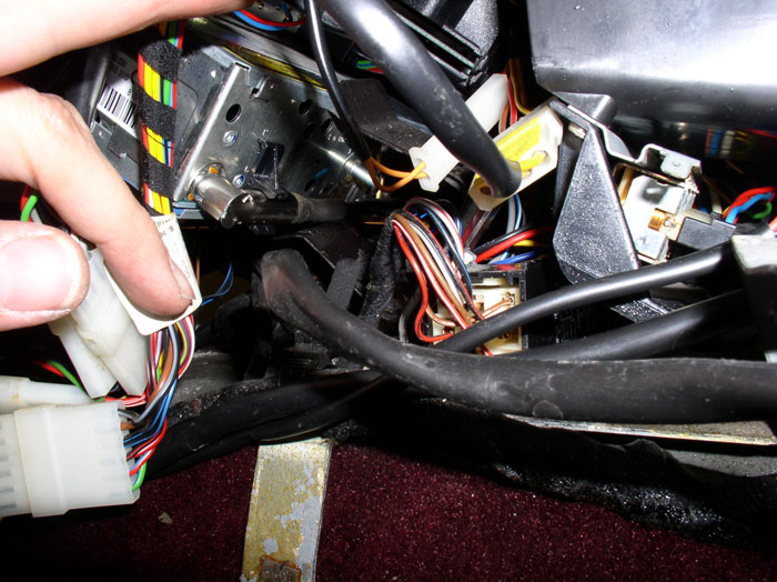
Underneath the console, connect the 6-wire and 4-wire leads from tlhe central warning strip to their matching wiring harness plugs as shown.
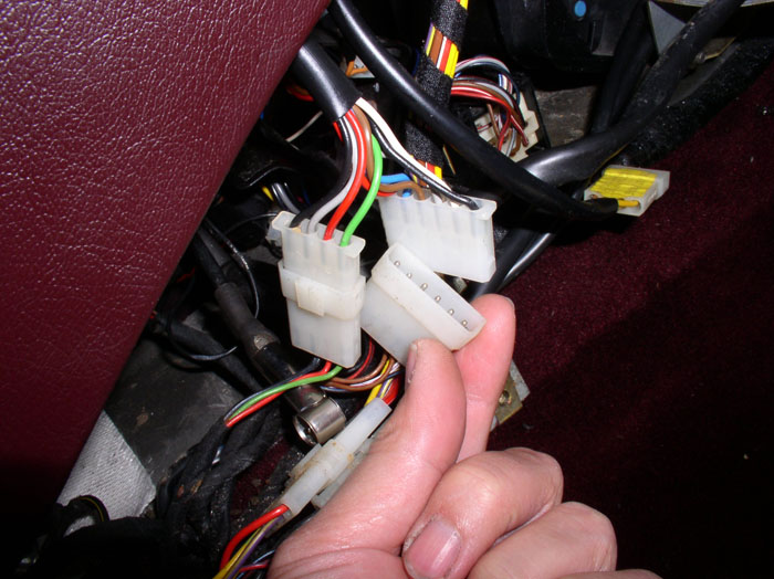
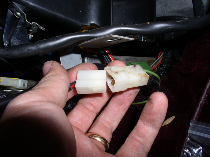
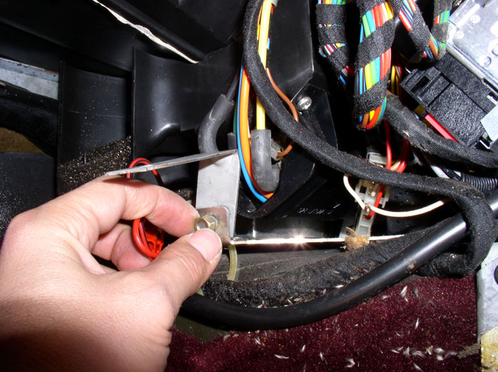
Locate the 4-wire and 2-wire leads from the shifter plate. Connect the 4-wire lead to its corresponding wiring harness plug as shown.
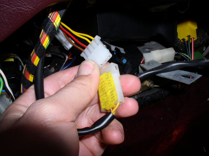
and connect the 2-wire lead to the wiring harness plug.
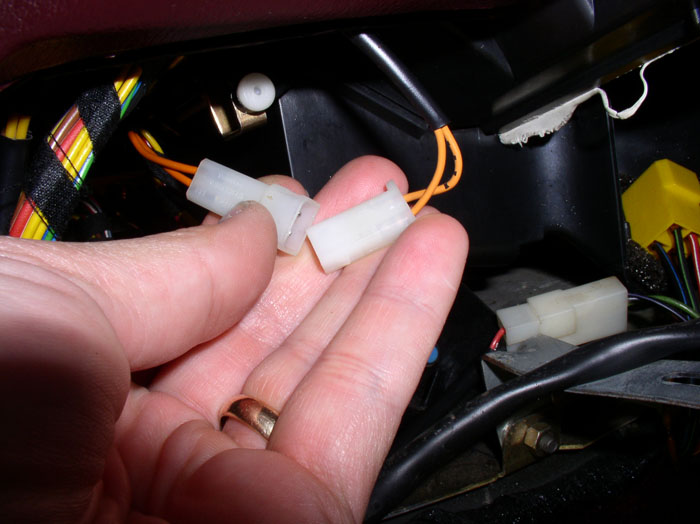
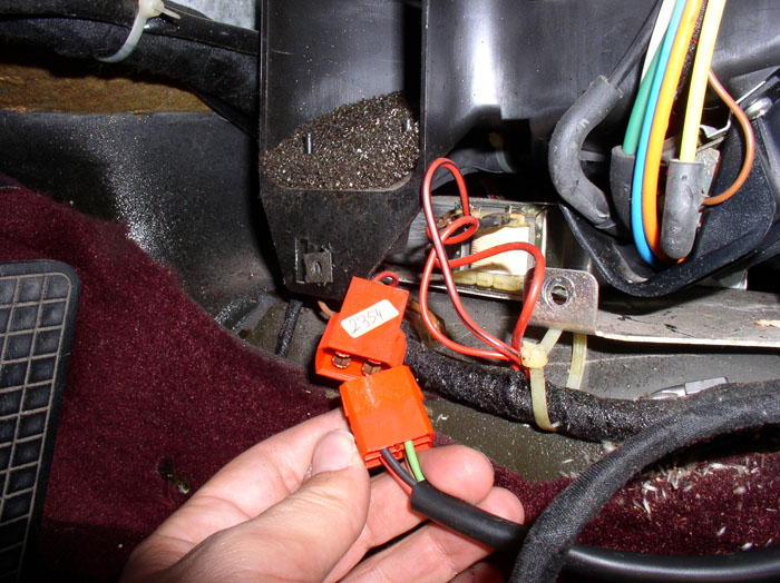
Next, position the A/C control unit near the center console opening and connect the rear wiring harness as shown.
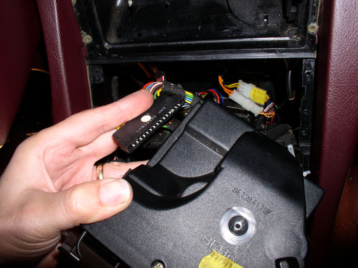
Then connect the front wiring harness.
Install the A/C control unit and central warning strip in their assigned positions in the center console.
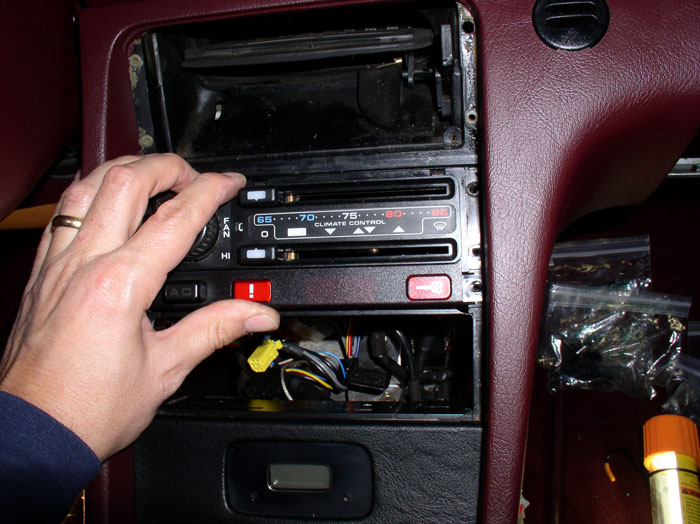
Secure the A/C control unit and central warning strip with their corresponding phillips screws (2 each side for the A/C control unit and 1 each side for the warning strip).
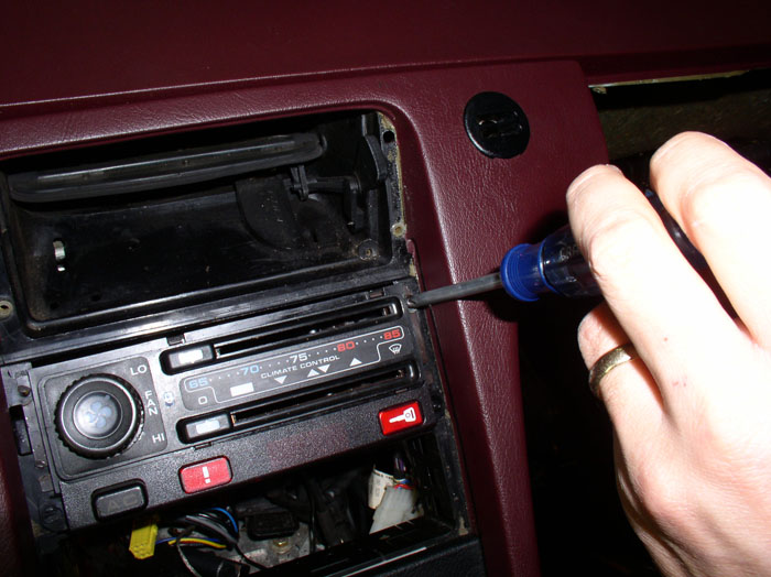
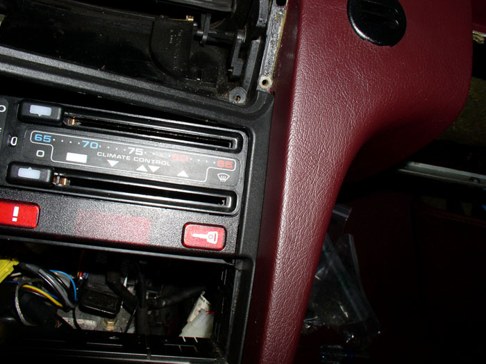
Next, install the console plastic trim piece. Position the trip piece on one side first....
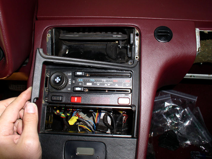
...and press into place. Then press the other side into place. It's a snug fit to get the other side in. To help get the other side in, I very carefully applied pressure to the horizontal piece of the trip (pulling up on the center piece) to allow it to slip into place a little easier.
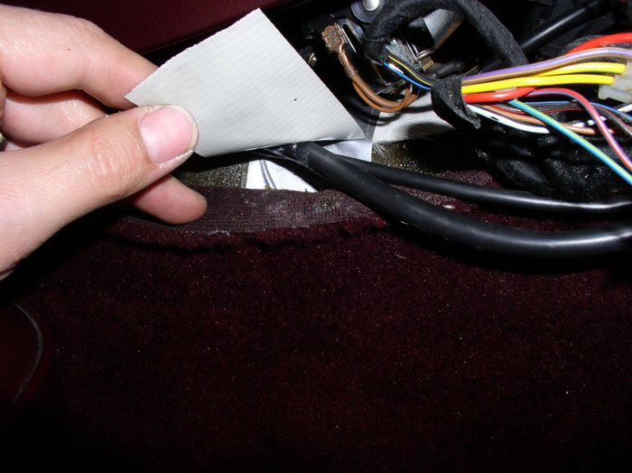
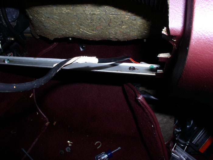
Position the window switch and rear wiper switch wiring harnesses on the passenger side under the duct tape that was attached to the heat shield cloth installed earlier. Do the same for the driver's side with the driver's side window switch wiring harness.
continued......
Connect the rear wiper switch wiring lead to the wiring harness. If you have a sunroof, connect it's wiring lead to the harness at this time.
On the driver's side, route the driver's window switch wiring lead behind the central locking module.
Then connect the window switch wiring lead to the wiring harness as shown.
Next, connect the A/C switch harness plug to the back of the A/C switch on the central warning strip as shown.
Underneath the console, connect the 6-wire and 4-wire leads from tlhe central warning strip to their matching wiring harness plugs as shown.
Locate the 4-wire and 2-wire leads from the shifter plate. Connect the 4-wire lead to its corresponding wiring harness plug as shown.
and connect the 2-wire lead to the wiring harness plug.
Next, position the A/C control unit near the center console opening and connect the rear wiring harness as shown.
Then connect the front wiring harness.
Install the A/C control unit and central warning strip in their assigned positions in the center console.
Secure the A/C control unit and central warning strip with their corresponding phillips screws (2 each side for the A/C control unit and 1 each side for the warning strip).
Next, install the console plastic trim piece. Position the trip piece on one side first....
...and press into place. Then press the other side into place. It's a snug fit to get the other side in. To help get the other side in, I very carefully applied pressure to the horizontal piece of the trip (pulling up on the center piece) to allow it to slip into place a little easier.
Position the window switch and rear wiper switch wiring harnesses on the passenger side under the duct tape that was attached to the heat shield cloth installed earlier. Do the same for the driver's side with the driver's side window switch wiring harness.
continued......
02-28-2009, 01:03 AM
#18
Rennlist Member
Thread Starter
Join Date: Sep 2007
Location: Ridgecrest, California
Posts: 1,363
Likes: 0
Received 143 Likes
on
28 Posts
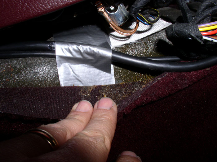
Slip the end of the duct tape under the carpet and press firmly into place.
Position the stereo unit near its assigned position in the console and re-connect the wiring connections at the rear of the unit (power, speakers, ground, and antenna).
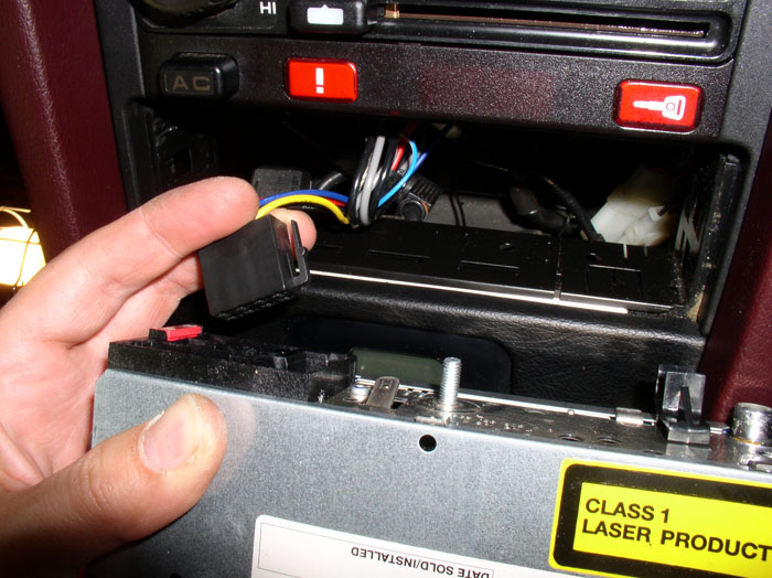
Carefully slide the stereo unit into its slot, guiding it from the rear while manuevering the wiring behind the unit out of the way. My unit had a "C" shaped receiver secured to the floor so I guided the stereo unit into the "C".
Press the stereo unit into place from the front until it is fully seated.
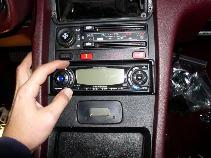
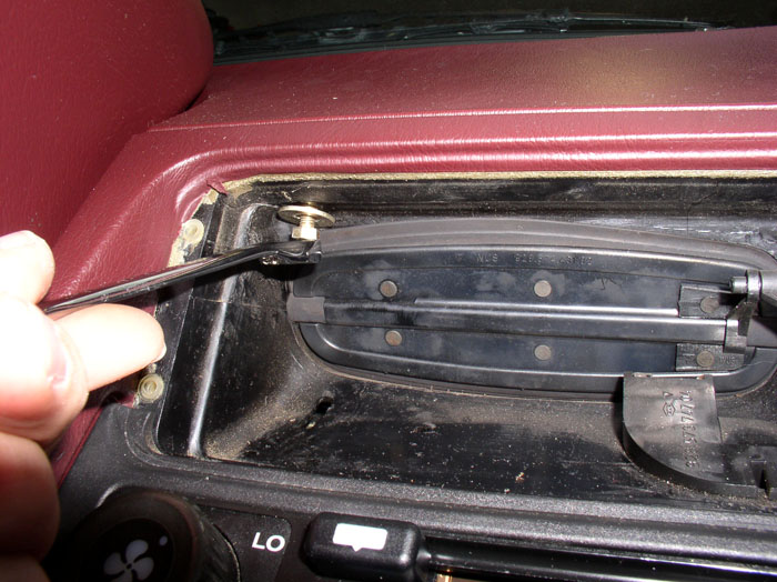
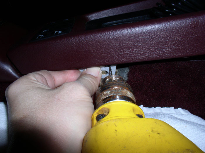
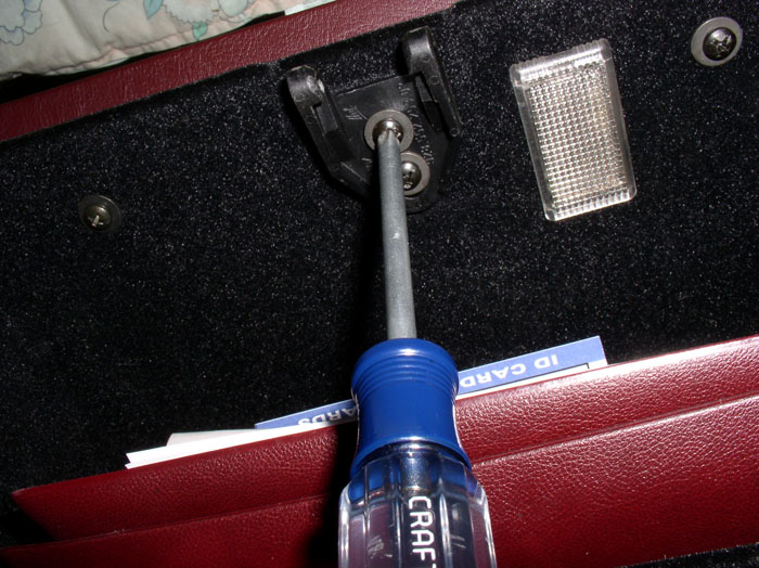
Install the two phillips screws that secure the bottom of the console to the dash. The passenger side is pictured here. Do the same for the two phillips screws on the driver's side.
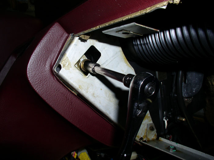
Install the underdash tray bracket (driver's side) using the 10mm nut and tighten down.
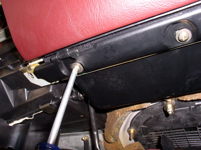
Install the two 8mm bolts above the center vent that secure the console to the dash.
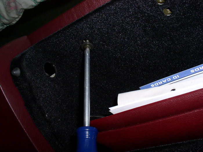
Install the 10mm screw at the glove box
Next, attach the sliding shifter plate to the shift lever by spreading the notched tabs slightly apart and insert the notches on both sides into their corresponding slots in the shift lever.
Install the shift boot and secure the bottom of the boot to the shift plate base. The boot should fit flush against the shift plate.
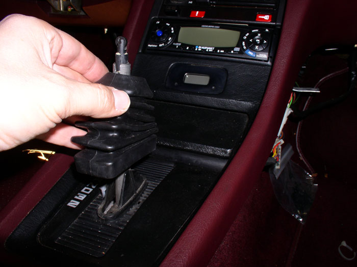
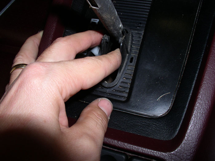
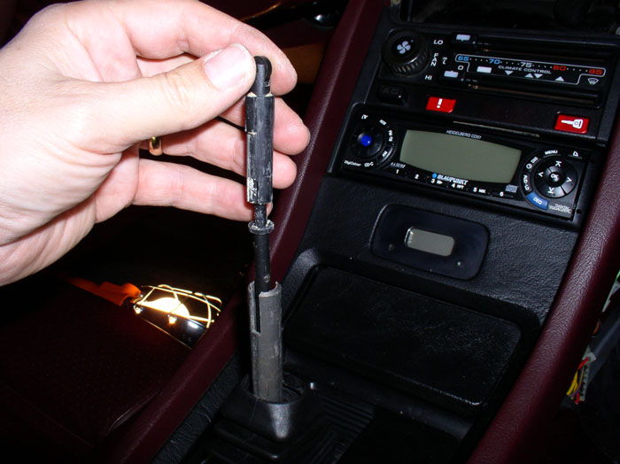
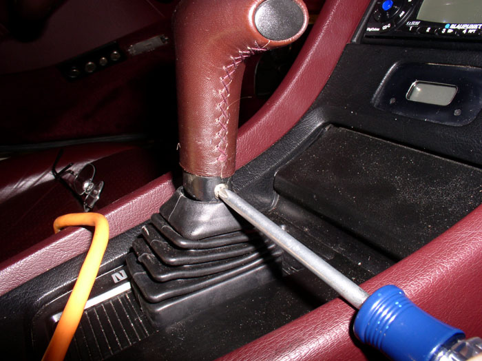
I decided to lubricate the shift locking release mechanism. It is easily removed by simply lifting up as shown.
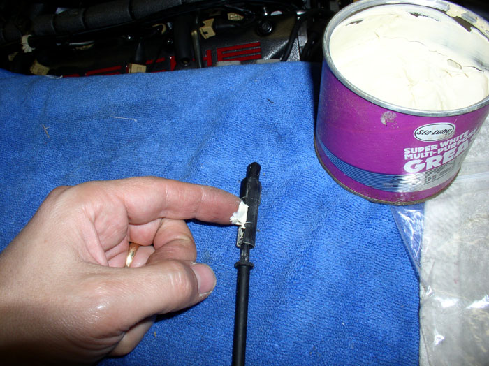
I lubricated the mechanism using general purpose white grease.
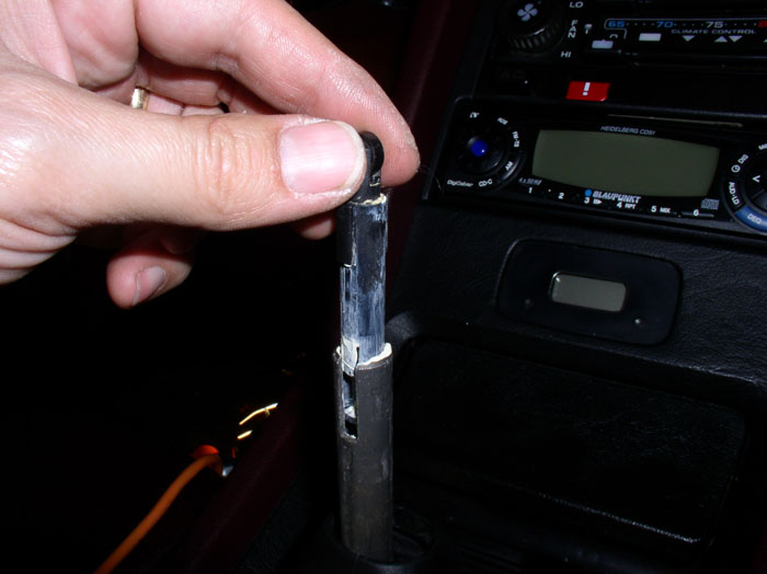
Then placed the shift locking mechanism back into the shift lever in the same orientation as it was originallly.
Next, install the shift handle lining up the two phillips screw holes. I tested the shift locking button to make sure it was lined up and working properly before tightening the handle mounting screws. If the locking mechanism isn't working properly, remove the handle, check for obstructions and try re-aligning the handle with the locking mechanism again. When it's working properly, tighten down both screws and raise the shift boot to cover the exposed screw heads.
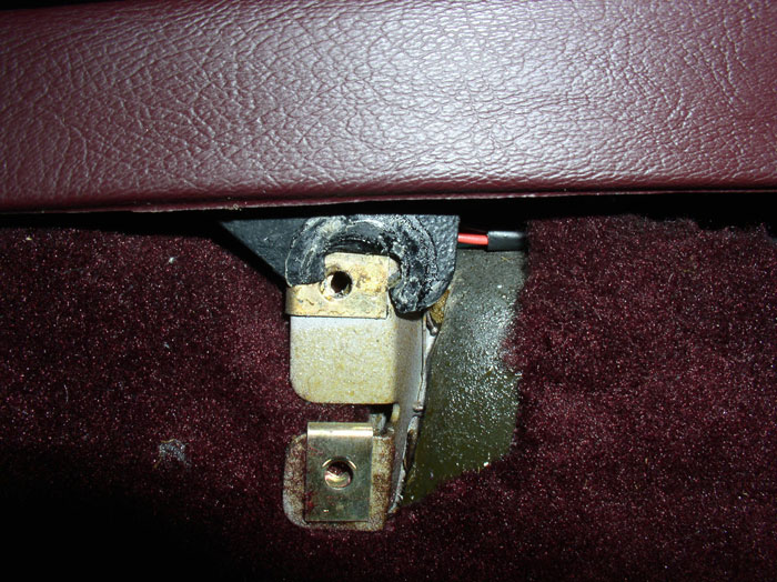
When I removed the rear mounting screws on the center console, the passenger side was broken in half as pictured below. I ordered the repair kit from Nichole.
continued......
Position the stereo unit near its assigned position in the console and re-connect the wiring connections at the rear of the unit (power, speakers, ground, and antenna).
Carefully slide the stereo unit into its slot, guiding it from the rear while manuevering the wiring behind the unit out of the way. My unit had a "C" shaped receiver secured to the floor so I guided the stereo unit into the "C".
Press the stereo unit into place from the front until it is fully seated.
Install the two phillips screws that secure the bottom of the console to the dash. The passenger side is pictured here. Do the same for the two phillips screws on the driver's side.
Install the underdash tray bracket (driver's side) using the 10mm nut and tighten down.
Install the two 8mm bolts above the center vent that secure the console to the dash.
Install the 10mm screw at the glove box
Next, attach the sliding shifter plate to the shift lever by spreading the notched tabs slightly apart and insert the notches on both sides into their corresponding slots in the shift lever.
Install the shift boot and secure the bottom of the boot to the shift plate base. The boot should fit flush against the shift plate.
I decided to lubricate the shift locking release mechanism. It is easily removed by simply lifting up as shown.
I lubricated the mechanism using general purpose white grease.
Then placed the shift locking mechanism back into the shift lever in the same orientation as it was originallly.
Next, install the shift handle lining up the two phillips screw holes. I tested the shift locking button to make sure it was lined up and working properly before tightening the handle mounting screws. If the locking mechanism isn't working properly, remove the handle, check for obstructions and try re-aligning the handle with the locking mechanism again. When it's working properly, tighten down both screws and raise the shift boot to cover the exposed screw heads.
When I removed the rear mounting screws on the center console, the passenger side was broken in half as pictured below. I ordered the repair kit from Nichole.
continued......
02-28-2009, 01:47 AM
#19
Rennlist Member
Thread Starter
Join Date: Sep 2007
Location: Ridgecrest, California
Posts: 1,363
Likes: 0
Received 143 Likes
on
28 Posts
Nicole sells a nice center console rear mounting tab repair kit which includes the metal reinforcement plates and mounting screws. THANKS Nicole!
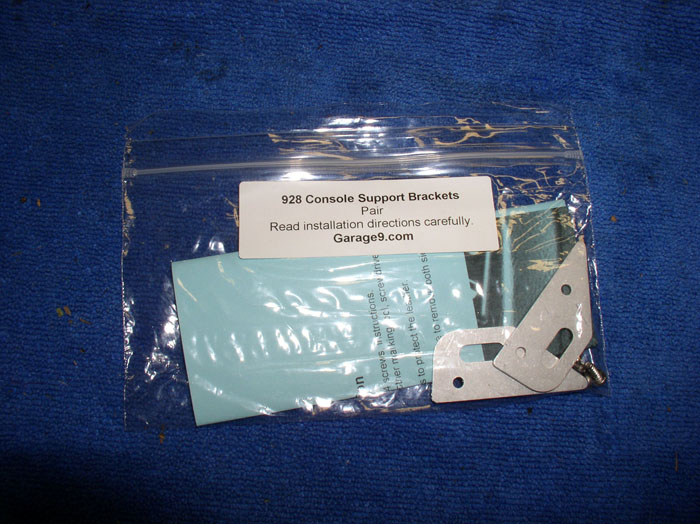
The repair kit can be used to repair a broken tab such as mine as long as enough of the original tab remains to secure the reinforcing screws. The kit can also be installed over an undamaged console mounting tab (such as my driver's side) to prevent the tab from breaking in the future. I installed both reinfocing plates on both tabs. I also ordered a second kit to have handy for the next center console I have to take off because I want to reinforce all my center console tabs with this kit. To install the repair kit, simply follow the directions included with the kit. Here's the steps I followed. First get a drill and 3/32" drill bit. Position the reinforcing plate over the rear mounting tab ensuring the center hole in the metal plate lines up with the hole in the plastic center console mounting tab.
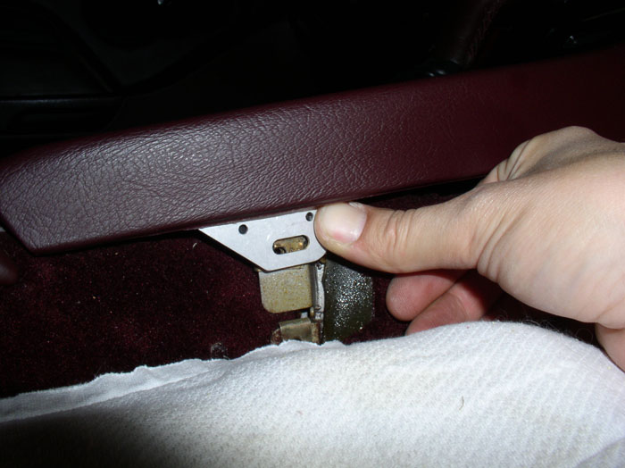
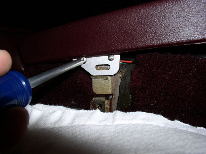
Then, drill a pilot hole in each of the 2 mounting holes on the reinforcing plate as shown.
Install the two phillips screws that mount the reinforcing plate. Perform the same operation on the driver's side.
Begin to install the rear mounting tab screw as shown.
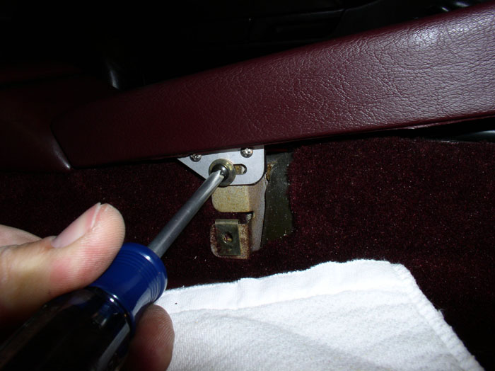
Ensure the center console is positioned correctly (evenly) at the rear and tighten the mounting tab screw down. Perform the same operation on the driver's side.
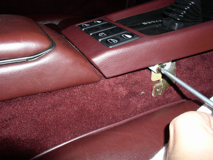
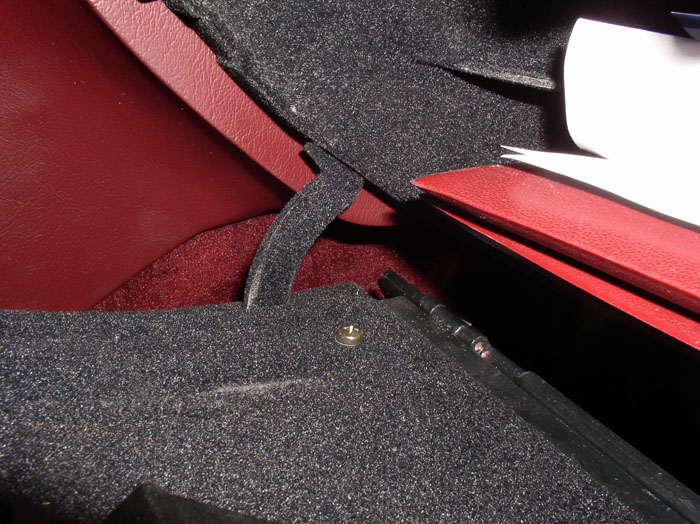
Next, position the console side cover by lining up the slot in the side cover with the under dash tray mounting bracket and sliding it over the underdash mounting bracket. Then, push the side panel up into the side panel groove located along the outer edge of the center console.
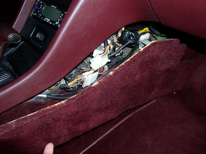
When you get to the rear of the console/side cover, you may notice the clearance between the side panel and the console is much reduced because of the mounting plate screws. The panel still fit but I had to carefully tuck the carpet up into the groove as I was pressing the side panel into the groove in the center console.
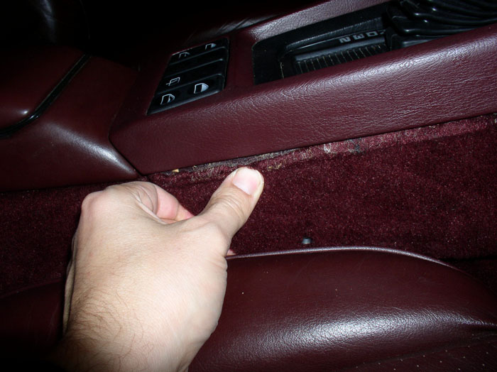
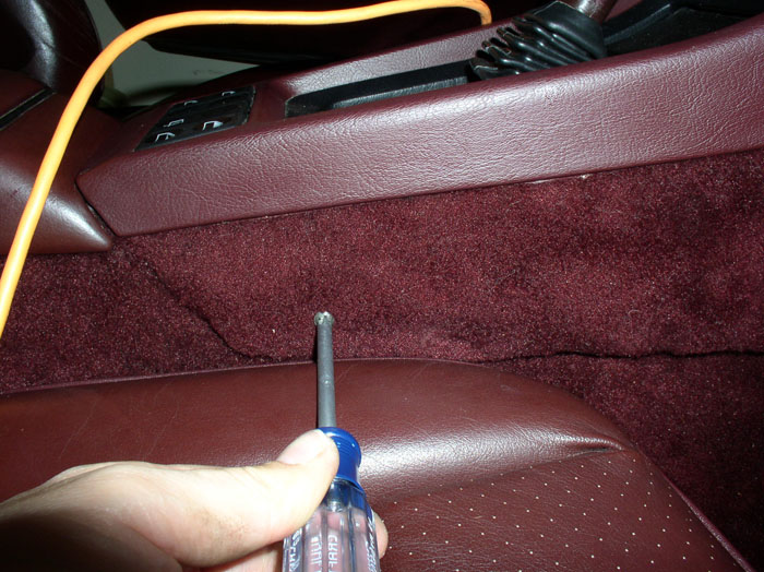
Then tighten the rear side panel mounting screw and the front side panel mounting screw (phillips). Repeat the side panel mounting sequence on the driver's side.
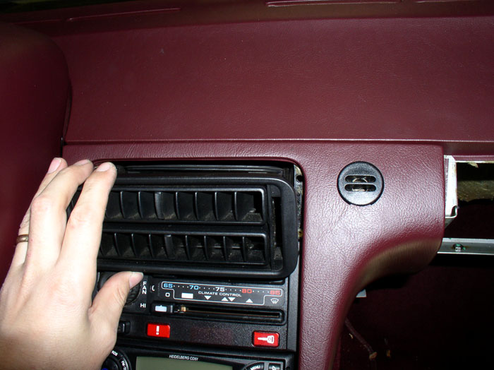
Position the center vent cover and press into place until it is fully seated and flush against the center console. Note that it has 4 notch pins that must line up with holes in the console for installation.
Next, position the glove box at the dashboard opening.
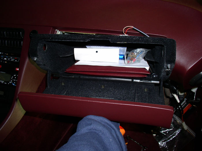
Route the glove box light wiring harness over the top of the dash lower rail as shown.
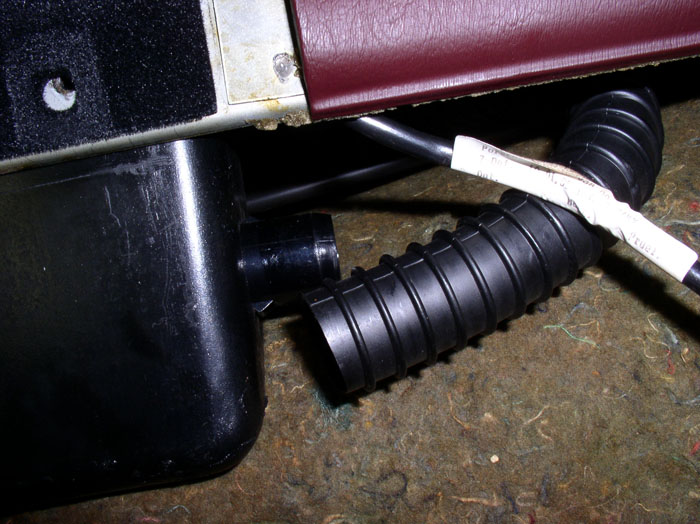
Attach the glove box vent hose to the port on the glove box.
Insert the glove box/door unit into the dash opening and install the two phillips screws that attach the top of the glove box to the dash, as shown.
Install the two screws that hold the glove box door catch but don't tighten down all the way. It will need to be adjusted later when checking operation of the glove box door.
continued......
The repair kit can be used to repair a broken tab such as mine as long as enough of the original tab remains to secure the reinforcing screws. The kit can also be installed over an undamaged console mounting tab (such as my driver's side) to prevent the tab from breaking in the future. I installed both reinfocing plates on both tabs. I also ordered a second kit to have handy for the next center console I have to take off because I want to reinforce all my center console tabs with this kit. To install the repair kit, simply follow the directions included with the kit. Here's the steps I followed. First get a drill and 3/32" drill bit. Position the reinforcing plate over the rear mounting tab ensuring the center hole in the metal plate lines up with the hole in the plastic center console mounting tab.
Then, drill a pilot hole in each of the 2 mounting holes on the reinforcing plate as shown.
Install the two phillips screws that mount the reinforcing plate. Perform the same operation on the driver's side.
Begin to install the rear mounting tab screw as shown.
Ensure the center console is positioned correctly (evenly) at the rear and tighten the mounting tab screw down. Perform the same operation on the driver's side.
Next, position the console side cover by lining up the slot in the side cover with the under dash tray mounting bracket and sliding it over the underdash mounting bracket. Then, push the side panel up into the side panel groove located along the outer edge of the center console.
When you get to the rear of the console/side cover, you may notice the clearance between the side panel and the console is much reduced because of the mounting plate screws. The panel still fit but I had to carefully tuck the carpet up into the groove as I was pressing the side panel into the groove in the center console.
Then tighten the rear side panel mounting screw and the front side panel mounting screw (phillips). Repeat the side panel mounting sequence on the driver's side.
Position the center vent cover and press into place until it is fully seated and flush against the center console. Note that it has 4 notch pins that must line up with holes in the console for installation.
Next, position the glove box at the dashboard opening.
Route the glove box light wiring harness over the top of the dash lower rail as shown.
Attach the glove box vent hose to the port on the glove box.
Insert the glove box/door unit into the dash opening and install the two phillips screws that attach the top of the glove box to the dash, as shown.
Install the two screws that hold the glove box door catch but don't tighten down all the way. It will need to be adjusted later when checking operation of the glove box door.
continued......
02-28-2009, 02:01 AM
#20
Rennlist Member
Thread Starter
Join Date: Sep 2007
Location: Ridgecrest, California
Posts: 1,363
Likes: 0
Received 143 Likes
on
28 Posts
Next, ensure the glove box door hinges line up with the corresponding slot in the glove box....
....and tighten the three phillips screws at the bottom of the glove box door.
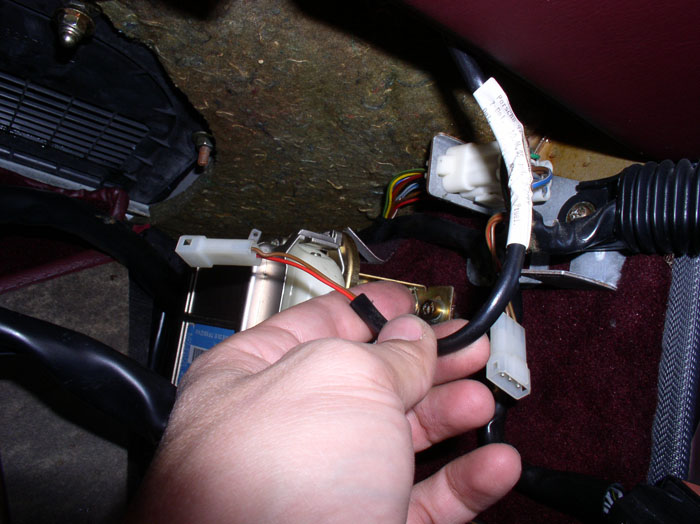
Finally, take the end of the glove box light wiring lead....
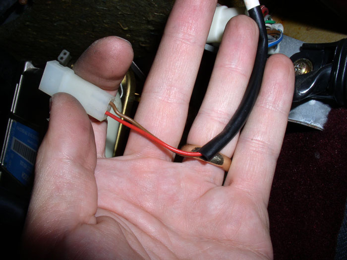
....and attach it to the wiring harness up behind the EZK and LH computers. Place the harness in the wire strap and secure as it was originally.
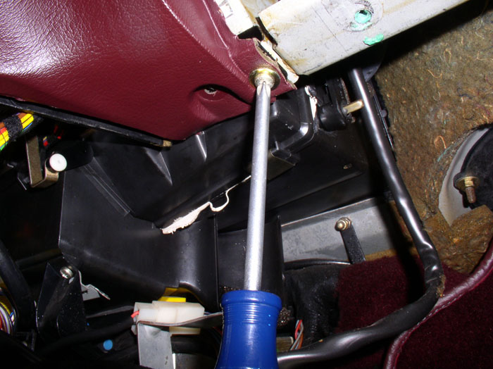
If you determined that you had a leaking defroster flap actuator, you will need to remove the instrumentation pod to get to it. Here is a step-by-step procedure to removing the pod (https://rennlist.com/forums/928-foru...cs-part-i.html). Since you do not need to disassemble the pod in order to get at the actuator, you can skip the part about removing the control ***** and instrument cluster in the aforementioned post. Simple pull the pod toward the rear of the car and rotate face down over the steering column to give you space to work. Once the pod is pulled over the steering column, you can easily access the defroster actuator.
At this point, you can re-install the under dash trays for both driver and passenger sides if desired. On my daily driver, I left them off because it gives me extra leg room. On my wife's daily driver, I re-installed them since she doesn't need the extra room. The installation is the reverse of what was documented at the beginning of this post.
Congratulations! Now you can start the car and try out your newly repaired HVAC air distribution/temperature control system. Please feel free to comment or provide improvement suggestions on this post - I'm always looking for ways to improve the quality of these posts. THANKS for reading!
....and tighten the three phillips screws at the bottom of the glove box door.
Finally, take the end of the glove box light wiring lead....
....and attach it to the wiring harness up behind the EZK and LH computers. Place the harness in the wire strap and secure as it was originally.
If you determined that you had a leaking defroster flap actuator, you will need to remove the instrumentation pod to get to it. Here is a step-by-step procedure to removing the pod (https://rennlist.com/forums/928-foru...cs-part-i.html). Since you do not need to disassemble the pod in order to get at the actuator, you can skip the part about removing the control ***** and instrument cluster in the aforementioned post. Simple pull the pod toward the rear of the car and rotate face down over the steering column to give you space to work. Once the pod is pulled over the steering column, you can easily access the defroster actuator.
At this point, you can re-install the under dash trays for both driver and passenger sides if desired. On my daily driver, I left them off because it gives me extra leg room. On my wife's daily driver, I re-installed them since she doesn't need the extra room. The installation is the reverse of what was documented at the beginning of this post.
Congratulations! Now you can start the car and try out your newly repaired HVAC air distribution/temperature control system. Please feel free to comment or provide improvement suggestions on this post - I'm always looking for ways to improve the quality of these posts. THANKS for reading!
02-28-2009, 07:01 AM
#21
Addict
Lifetime Rennlist
Member
Lifetime Rennlist
Member
Hi Dwayne,
Excellent pictures as always. Thanks for adding this really helpful stuff.
PS. the comb flap actuator can be removed without drilling. Pull the actuator out and twist. The actuator arm will ''roll'' off the locking pin. It helps to support the flap arm from the side while doing this.
Excellent pictures as always. Thanks for adding this really helpful stuff.
PS. the comb flap actuator can be removed without drilling. Pull the actuator out and twist. The actuator arm will ''roll'' off the locking pin. It helps to support the flap arm from the side while doing this.
02-28-2009, 07:32 AM
#22
Nordschleife Master
Yep, I found an old post about this when I did mine a couple of months ago, the twist works just fine. You can push the actuator arm back on through the large vent hole out to the passenger door.
02-28-2009, 10:35 AM
#24
Rennlist Member
Thread Starter
Join Date: Sep 2007
Location: Ridgecrest, California
Posts: 1,363
Likes: 0
Received 143 Likes
on
28 Posts
THANK YOU ALL for the generous comments and great feedback!
I learned something new here! Great tip  I will try this on my next comb flap repair as you suggest. In the meantime, I will update the post to include this alternative method of disconnecting the lever arm. I also want to insert a picture and a few words on testing the solenoids for leaks to make it complete. THANKS for the tip and the help in improving the quality of this post.

WHAT?? You're actually supposed to DRIVE these cars??!!
Hi Dwayne,
Excellent pictures as always. Thanks for adding this really helpful stuff.
PS. the comb flap actuator can be removed without drilling. Pull the actuator out and twist. The actuator arm will ''roll'' off the locking pin. It helps to support the flap arm from the side while doing this.
Excellent pictures as always. Thanks for adding this really helpful stuff.
PS. the comb flap actuator can be removed without drilling. Pull the actuator out and twist. The actuator arm will ''roll'' off the locking pin. It helps to support the flap arm from the side while doing this.
I will try this on my next comb flap repair as you suggest. In the meantime, I will update the post to include this alternative method of disconnecting the lever arm. I also want to insert a picture and a few words on testing the solenoids for leaks to make it complete. THANKS for the tip and the help in improving the quality of this post.
WHAT?? You're actually supposed to DRIVE these cars??!!
03-01-2009, 06:52 AM
#25
Pro

Join Date: Mar 2004
Location: Perth, Western Australia
Posts: 715
Likes: 0
Received 13 Likes
on
12 Posts
I still think Dwayne does all these jobs twice.
Once to do the repair and clean everything, the second time to take the photos - all so his hand model doesn't get a grease smudge.
Once to do the repair and clean everything, the second time to take the photos - all so his hand model doesn't get a grease smudge.
03-01-2009, 11:29 PM
#26
Rennlist Member
Thread Starter
Join Date: Sep 2007
Location: Ridgecrest, California
Posts: 1,363
Likes: 0
Received 143 Likes
on
28 Posts
You're not far off - If you only knew what went on behind the scenes on my projects! Being a Noob, sometimes I have to repeat a procedure multiple times to get it right. It would be highly entertaining to capture and publish my many outtakes and bloopers such as the flaming homebuilt smoke tester! I LOVE this work!
....and yes, the hand model demands double pay if it gets a grease smudge.
 This may be your best one yet. Best thing is I need to do this soon. Thanks Buddy
03-23-2009, 10:31 PM
This may be your best one yet. Best thing is I need to do this soon. Thanks Buddy
03-23-2009, 10:31 PM
#29
Burning Brakes

I am following Dwanyne's excellent write up to resolve vaccum issues on my '85. I had leaks in both of the same actuators and the solenoid manifold.
My problem is the comb flap connection for the actuator, I used the twist routine to pop it off (works fine) but I can not seem to see the connecting point to reattach.
I assume they are all the same but mine has a horizontal fixed plastic divider about the same elevation as the actuator. If I put the lever arm on top where I can see it, I can't see where it connects. If I put it below then I can not see the connection either.
I drilled the hole in Dwayne's original process to see if that resolved the problem but still can not see what I am missing.
Any help would be greatly appreciated.
03-23-2009, 10:48 PM
#30
Rennlist Member
Thread Starter
Join Date: Sep 2007
Location: Ridgecrest, California
Posts: 1,363
Likes: 0
Received 143 Likes
on
28 Posts
Hello Roger,
Just got your PM - Unfortunately, I was enroute on travel (again) to Maryland so couldn't get back to your earlier. I found that a snake light helps to see things in the air distribution box (especially since you have the 3/4" hole in the front as well. Can you see the plastic lock pin on the comb flap arm when looking into the air distribution box from the port hole behind the glove box??
I may have a better picture at home but won't be back there until Friday afternoon/evening. Perhaps someone here has a good picture of the connection point until then?