
'87 HVAC Vacuum Leak Testing and Repair Procedure w/pics
 02-22-2009, 07:32 PM
#1
Rennlist Member
Thread Starter
Join Date: Sep 2007
Location: Ridgecrest, California
Posts: 1,363
Likes: 0
Received 143 Likes
on
28 Posts
Some of the HVAC controls on Virginia were not working correctly when we first got her so I did some testing, found the problem and made the repair during the time when I had the engine all tore apart. Since this was my first attempt to repair the HVAC vacuum system, I used John Pirtle's outstanding writeup on the subject and found it extremely valuable. THANKS, John!
This is another Newbie rated thread with lots of pictures for those like me that have not tried this before and would like a step-by-step pictorial guide. Even though there are 4 vacuum actuators of interest in the HVAC system, I only needed to repair 2 since the other 2 were still working famously. The two that will be discussed in this thread are the Footwell Flap actuator and the comb flap actuator.
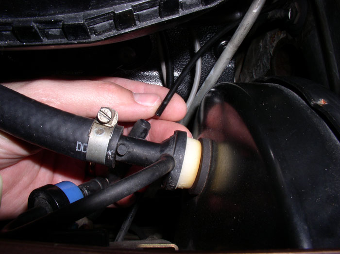
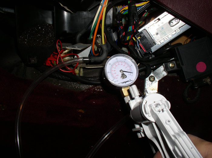
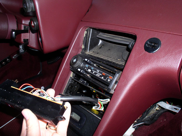
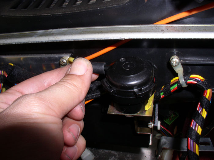
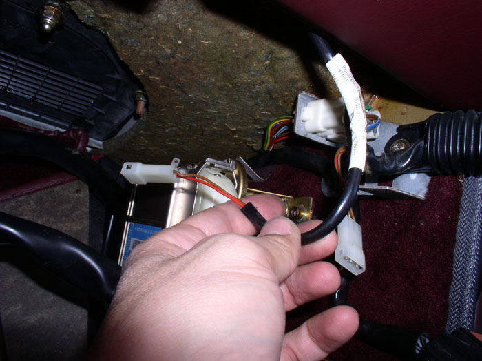
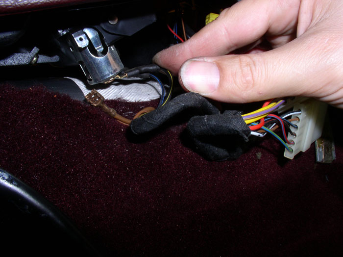
First, if you suspect some problems with the HVAC vacuum system, you can verify it rather easily without taking anything apart (except one vacuum hose near the brake booster). You will need a vacuum pump (such as a MityVac). Locate the black HVAC vacuum source (input) line that is located just under the brake booster. Disconnect it from the 4-way splitter as shown - and back by popular demand, my hand model!
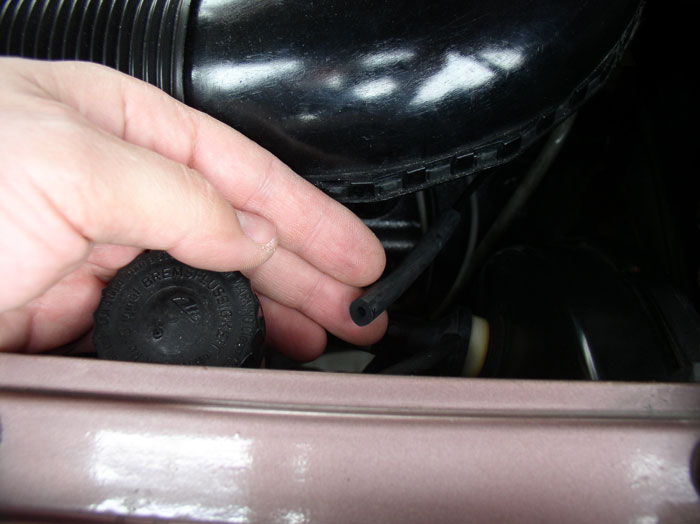
Next, I use a small rubber vacuum hose extension (about 6") and attach the rubber hose to the HVAC source line.
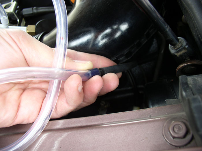
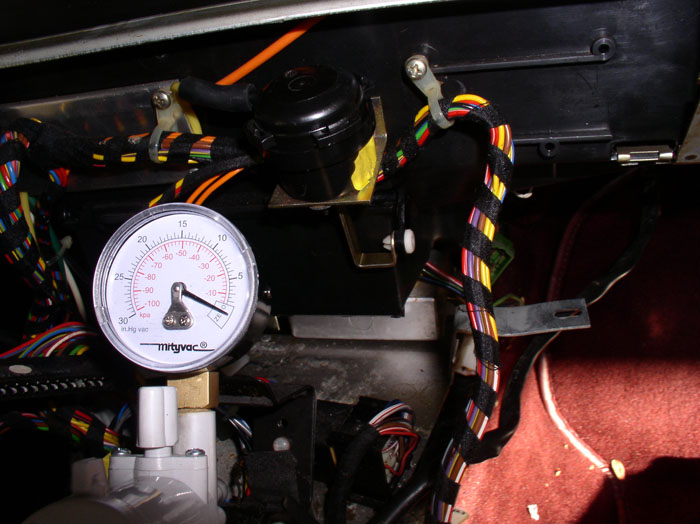
Then attach your vacuum pump to the rubber hose extension.
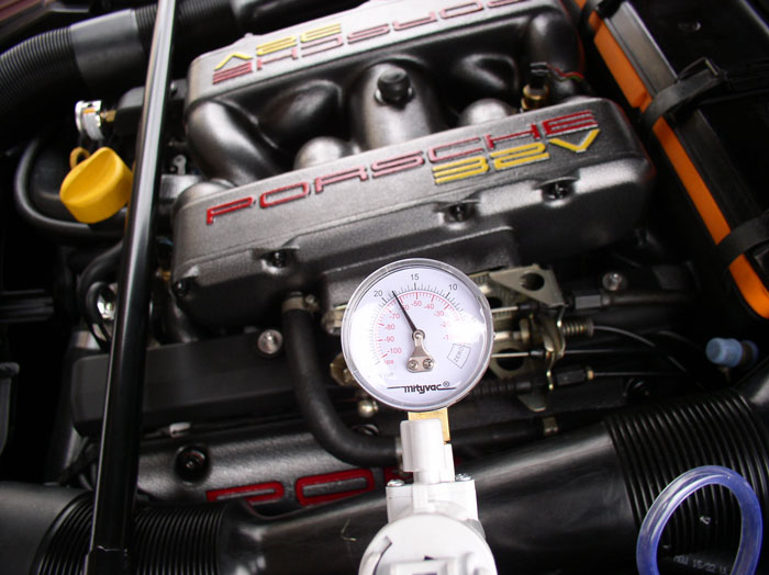
I pump the vacuum up to about 17-18 Inches HG. If there are no leaks between the vacuum pump and the vacuum manifold inside the center console, it should hold vacuum.
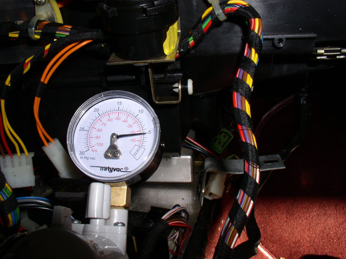
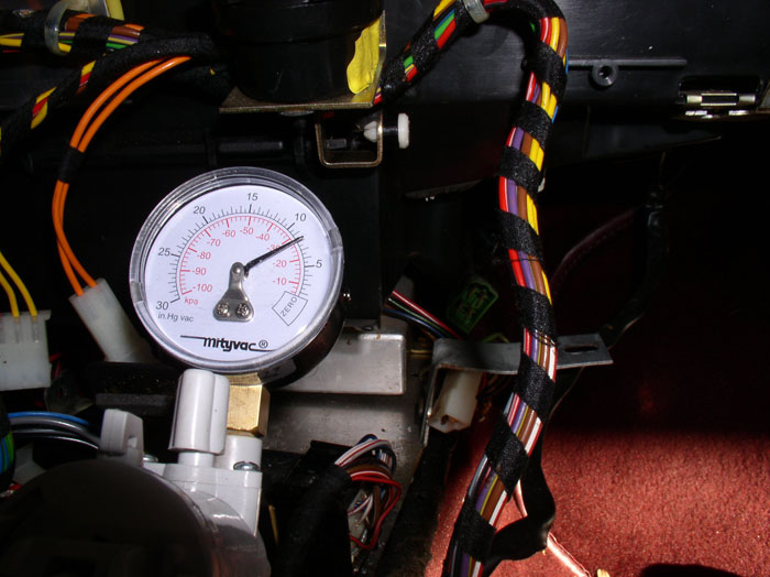
If you are leaking vacuum at this point, check the line from the vacuum pump into the firewall. If no leaks yet, insert the key in the ignition and turn the key to the "run" position (or you can simply start the car). This will power the electric solenoids that divert vacuum to the vacuum actuators in the HVAC system. You will notice a drop in the vacuum on the vacuum pump as vacuum is routed to the actuators in the HVAC system. Begin pumping the vacuum back up (about 12-15 pumps) until you get back to about 15 Inches HG. See if it will hold vacuum at this point. If it holds vacuum, you can try moving the HVAC control slider **** on the head unit and see if it holds vacuum in all positions. If you see vacuum steadily dropping, you have a leak.
Once you have confirmed you have a leak, you can gather your tools and parts. Here's the commonly used tools I used for the procedure:
Phillips screwdriver (including a stubby or 90 degree phillips)
10mm socket, extension, ratchet
3/4" drill bit, drill
3/4" plastic or rubber body plug
MityVac Vacuum pump
Replacement Vacuum Diaphrams (I ordered all 4 diaphrams from Roger before digging in because I wanted to have all the parts I would need in case they were all bad). Roger had 3 of the 4 vacuum diaphrams and the defroster vacuum actuator itself - so I was all set.
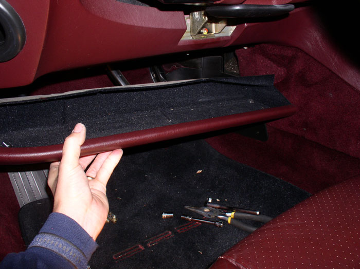
You will need to remove the center console side panels in order to get at the HVAC vacuum manifold to conduct further testing and pinpoint the leak. First, remove the under dash shelves/trays on the driver's side and passenger side. Use a 10mm socket on the two acorn nuts under the dash as shown.
Next, remove the 10mm nut on the right end of the tray.
Then the 10mm nut on the left side of the tray. It's easier to use an extension for this nut.
Once the nut is off the left side, pop the carriage bolt up and out. This will make it easier to remove the tray. Bag and mark the hardware so it doesn't get lost.
Now you can manuever the tray out.
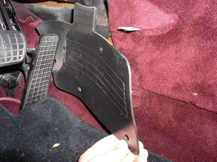
Next, remove the foot guard. It's held in place by three phillips screws. Take all three out....
...and remove the plastic guard. Note that at the far end of the guard, there is a notched tab that fits behind the accelerator and locks the guard in place (unfortunately not pictured here - it's blocked by the accelerator here).
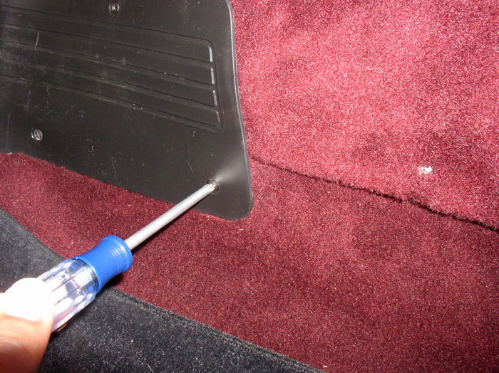
Next, remove the side panel by removing the two phillips screws - one is located near the front as shown.
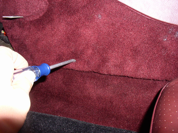
Remove the rear pillips screw located as shown.
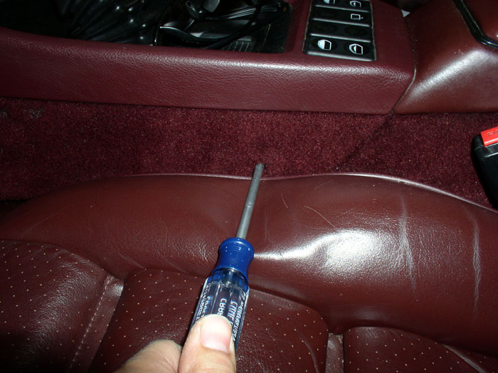
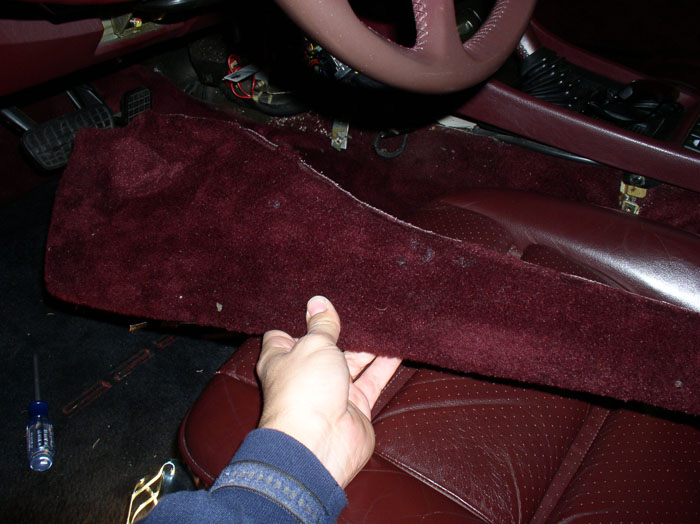
Then pull the side panel down removing it from its groove in the console.
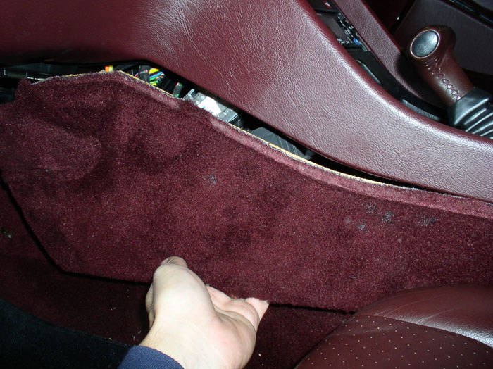
Pull the front end of the panel out toward the car door to remove it from the metal tray bracket and pull out the panel.
Unfortunately, I've got to head out of town again for work so I'll continue with this post when I return in a couple of days.
continued.....
This is another Newbie rated thread with lots of pictures for those like me that have not tried this before and would like a step-by-step pictorial guide. Even though there are 4 vacuum actuators of interest in the HVAC system, I only needed to repair 2 since the other 2 were still working famously. The two that will be discussed in this thread are the Footwell Flap actuator and the comb flap actuator.
First, if you suspect some problems with the HVAC vacuum system, you can verify it rather easily without taking anything apart (except one vacuum hose near the brake booster). You will need a vacuum pump (such as a MityVac). Locate the black HVAC vacuum source (input) line that is located just under the brake booster. Disconnect it from the 4-way splitter as shown - and back by popular demand, my hand model!
Next, I use a small rubber vacuum hose extension (about 6") and attach the rubber hose to the HVAC source line.
Then attach your vacuum pump to the rubber hose extension.
I pump the vacuum up to about 17-18 Inches HG. If there are no leaks between the vacuum pump and the vacuum manifold inside the center console, it should hold vacuum.
If you are leaking vacuum at this point, check the line from the vacuum pump into the firewall. If no leaks yet, insert the key in the ignition and turn the key to the "run" position (or you can simply start the car). This will power the electric solenoids that divert vacuum to the vacuum actuators in the HVAC system. You will notice a drop in the vacuum on the vacuum pump as vacuum is routed to the actuators in the HVAC system. Begin pumping the vacuum back up (about 12-15 pumps) until you get back to about 15 Inches HG. See if it will hold vacuum at this point. If it holds vacuum, you can try moving the HVAC control slider **** on the head unit and see if it holds vacuum in all positions. If you see vacuum steadily dropping, you have a leak.
Once you have confirmed you have a leak, you can gather your tools and parts. Here's the commonly used tools I used for the procedure:
Phillips screwdriver (including a stubby or 90 degree phillips)
10mm socket, extension, ratchet
3/4" drill bit, drill
3/4" plastic or rubber body plug
MityVac Vacuum pump
Replacement Vacuum Diaphrams (I ordered all 4 diaphrams from Roger before digging in because I wanted to have all the parts I would need in case they were all bad). Roger had 3 of the 4 vacuum diaphrams and the defroster vacuum actuator itself - so I was all set.
You will need to remove the center console side panels in order to get at the HVAC vacuum manifold to conduct further testing and pinpoint the leak. First, remove the under dash shelves/trays on the driver's side and passenger side. Use a 10mm socket on the two acorn nuts under the dash as shown.
Next, remove the 10mm nut on the right end of the tray.
Then the 10mm nut on the left side of the tray. It's easier to use an extension for this nut.
Once the nut is off the left side, pop the carriage bolt up and out. This will make it easier to remove the tray. Bag and mark the hardware so it doesn't get lost.
Now you can manuever the tray out.
Next, remove the foot guard. It's held in place by three phillips screws. Take all three out....
...and remove the plastic guard. Note that at the far end of the guard, there is a notched tab that fits behind the accelerator and locks the guard in place (unfortunately not pictured here - it's blocked by the accelerator here).
Next, remove the side panel by removing the two phillips screws - one is located near the front as shown.
Remove the rear pillips screw located as shown.
Then pull the side panel down removing it from its groove in the console.
Pull the front end of the panel out toward the car door to remove it from the metal tray bracket and pull out the panel.
Unfortunately, I've got to head out of town again for work so I'll continue with this post when I return in a couple of days.
continued.....

 02-22-2009, 10:15 PM
#3
Race Director
NOTE.....once you remove the plastic shroud that covers the solenoid strip there is ONE bolt right in the middle that is a PITA to get out...just don't put it back when your done!! (ask me how I know)
02-23-2009, 08:17 AM
#5
Racer
Very good,
I worked on my sharks last friday. I suspecty for a long time, that the flap resonator was inoperative. I cheked it last week and discovered that I had the same leak as yours.
I will be looking over this thread to see how repair it.
Thanks
Puyi
I worked on my sharks last friday. I suspecty for a long time, that the flap resonator was inoperative. I cheked it last week and discovered that I had the same leak as yours.
I will be looking over this thread to see how repair it.
Thanks
Puyi
02-26-2009, 12:33 AM
#6
Rennlist Member
Thread Starter
Join Date: Sep 2007
Location: Ridgecrest, California
Posts: 1,363
Likes: 0
Received 143 Likes
on
28 Posts
OK....made it back from travel and back to this post.
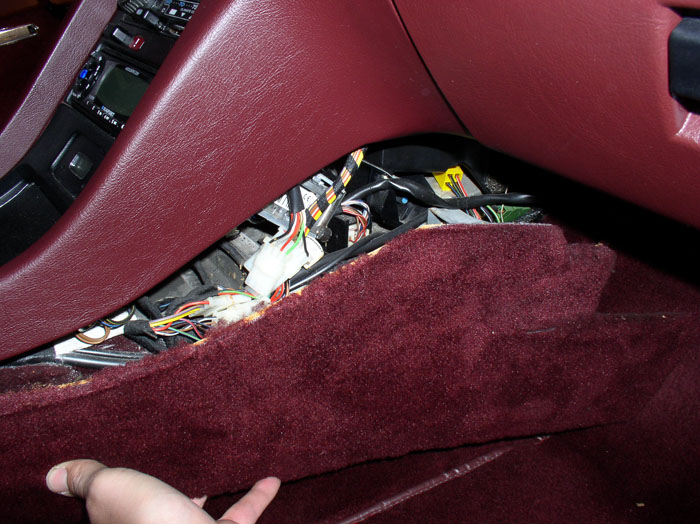
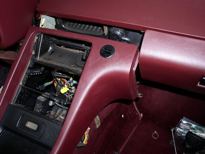
After removing the console side panel, you will notice the hard plastic vacuum hoses in multiple colors that feed the various vacuum actuators of the HVAC system. These will be described in a moment.
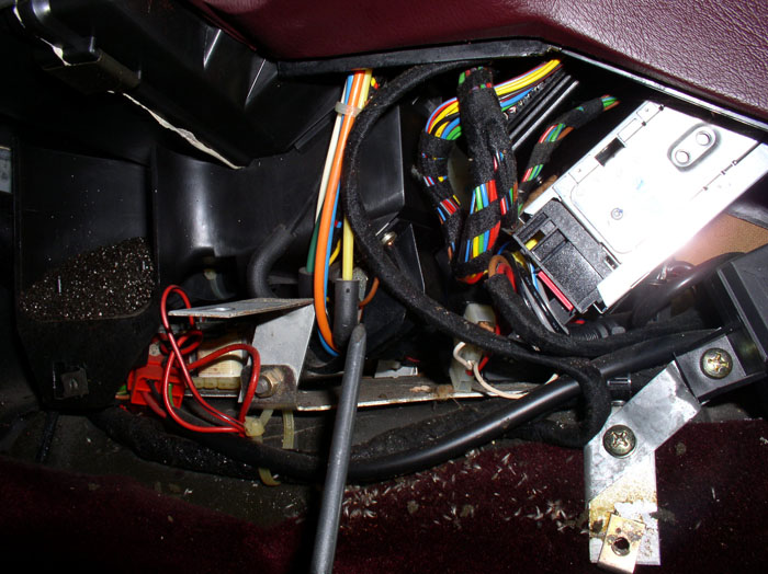
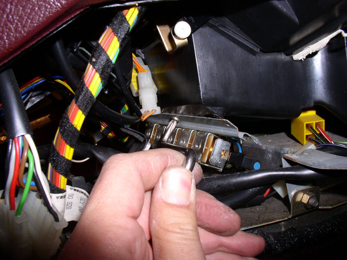
You have a couple of options here to conduct the next test. You will notice you can't access all of the vacuum hose connections at the solenoid. In fact, I could only access the last one (yellow, pictured below) to pull the vacuum line and test with the MightyVac. You can cut each of the hard lines and attach the MightyVac to the end of the hose that runs up into the dash. If everything checks out, you can simply re-connect the severed connection with a rubber vacuum hose coupling. The other option you have is to remove the vacuum solenoid console (which is what I did) so you can access all the vacuum line connections at the solenoids and test the lines without cutting. I discovered here that my yellow line (goes to the footwell flap vacuum actuator) had a leak so I was going to have to remove the center console anyway to repair it. I might as well remove the solenoid console to test the rest of the actuators for leaks.
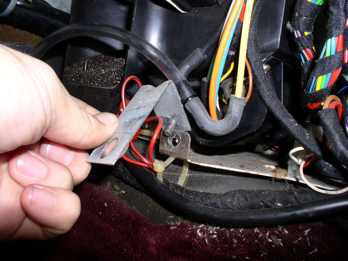
Next, remove the brace that holds the under dash tray. It's held on by a 10mm nut.
Going over to the passenger side, remove the underdash tray and center console cover as you did on the driver's side. One difference you will notice is the passenger side underdash tray has a lamp monitor attached to the outer end of the tray (near the car door). You can either disconnect the electrical harness or remove the monitor box from the tray with the two mounting bolts in order to remove the tray.
Remove the center console side cover.
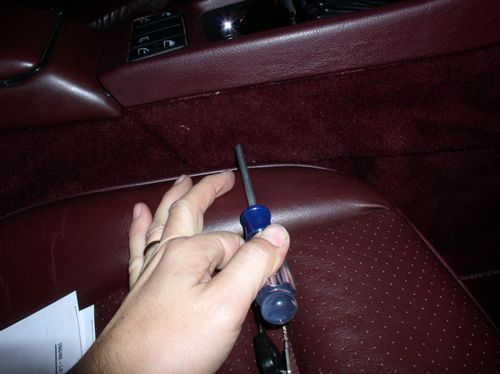
You will find a phillips screw that holds the solenoid console protective cover in place (see pic). Remove the phillips screw.
You will find the same screw on the driver's side. Remove it as well.
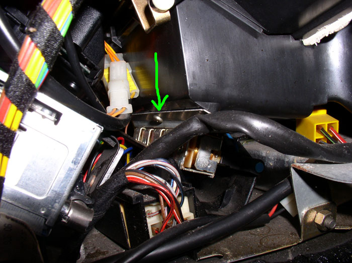
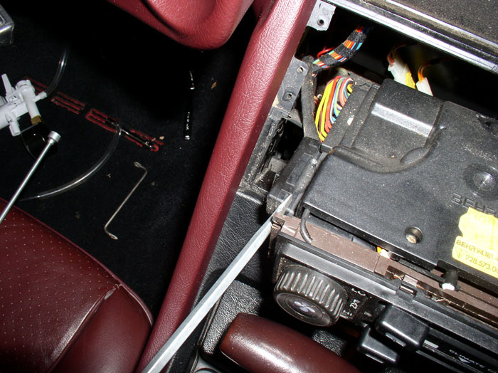
Once the screws are removed, the cover will drop down. The solenoid console is held in place by one final phillips screw in the center of the mounting bracket (see arrow in pic). There isn't much room to remove this screw.....
....In order to gain a little more working room, I pulled out the vacuum solenoid console cover as shown.....
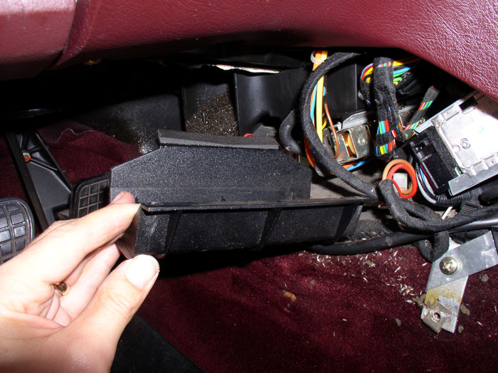
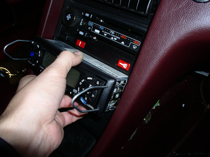
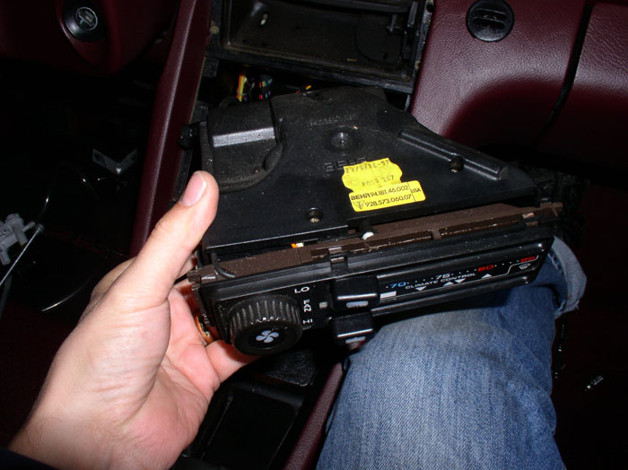
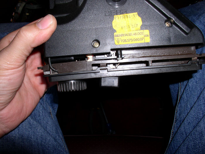
....and pulled out the radio a few inches. In order to pull out the radio, you will need the installation "keys" to pull the radio (your radio will differ). Since I was going to have to remove the radio as part of the console removal process anyway, this seemed like a reasonable thing to do.
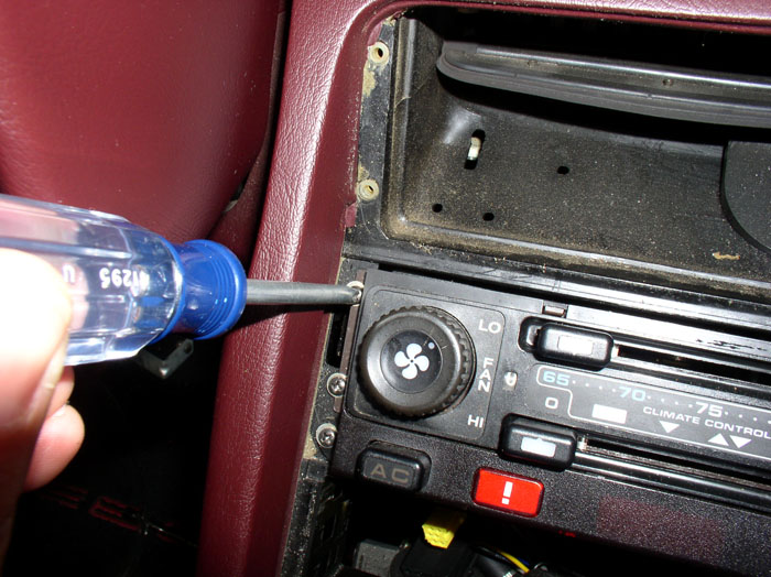
With a little more room to work with, I used a 90 degree phillips screwdriver to get the screw out. A stubby phillips screwdriver works well here too.
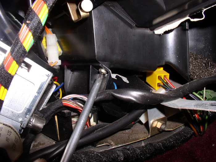
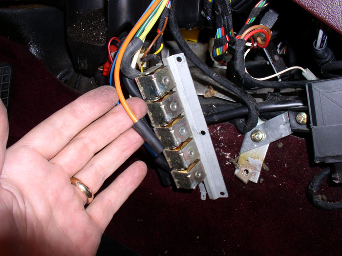
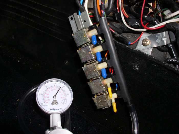
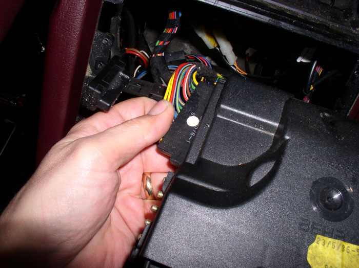
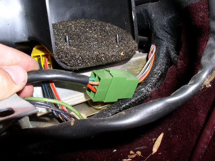
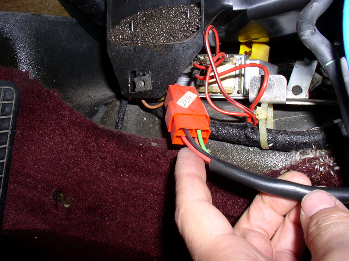
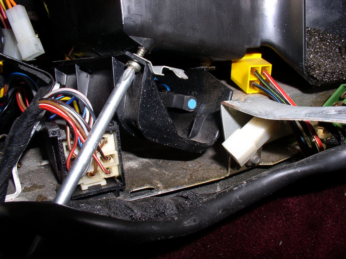
With the center screw removed, you can pull out the solenoid console out the driver's side as shown. There is one vacuum source line (black) and 5 output lines - one from each solenoid. They are marked in the pic below as to what function each color line performs and the location of the vacuum actuator. Yellow goes to the footwell flap, green goes to the defrost flap, orange goes to the comb flap, white goes to the hot water control valve, and blue goes to the recirculation flap.
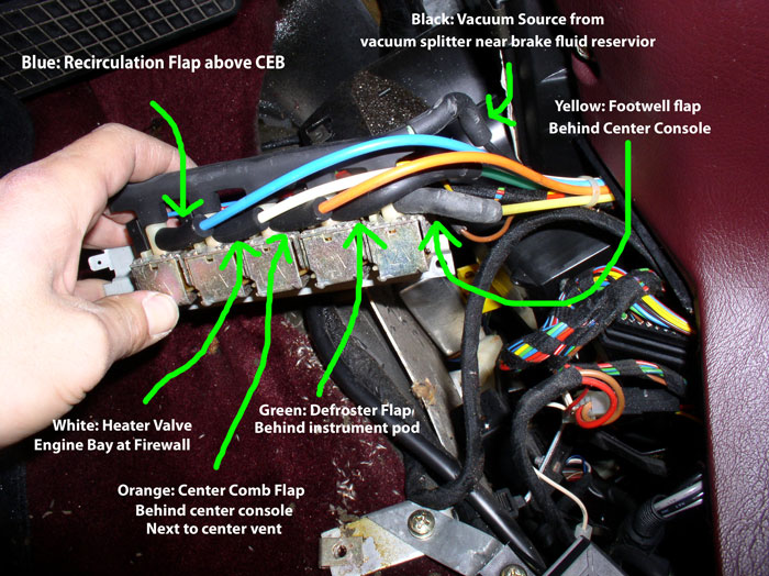
You can test each line one at a time by disconnecting the line from the solenoid and attaching the mightyvac to the rubber hose connection. I applied about 15 inches HG and listened for the flap movement and watched the vacuum gauge to see if it would hold vacuum. If everything checked out, I reconnected the line and move to the next. I found that I had a leak in the Yellow (footwell flap) and the orange (comb flap) lines. The rest of the lines all held vacuum and operated the flaps. For me, the next steps would be to remove the center console to get at the to leaking actuators. If you find that you have a leaking defroster actuator, you will need to remove the instrumentation pod to get to it. If the hot water control valve is leaking vacuum, you will need to remove the air filter box in the engine bay in order to get at the actuator. If you have a leak in the recirculation flap, you will need to remove the fan blower motor and recirculation box above the CEB to get at the actuator.
If you have tested all the vacuum lines to their respective actuators and did not find a leak, then the leak is most likely in one of the vacuum solenoids. There are 5 solenoids and any one or all may be leaking vacuum. Even if you found a leak at one of the actuators, it's a good idea to test the solenoids as well - and now is the perfect time. The quick and easy way to test all the solenoids at once is to hook up the mighty vac to the rubber vacuum manifold where the source vacuum line (black line) comes in. Disconnect all the vacuum lines that go to the actuators and cap the vacuum port at the solenoid with a vacuum cap as shown below. Pump up the vacuum to about 15 inches Hg and turn the ignition switch to "run". If the vacuum does not hold, then you have a leak in one or more of the solenoids. When I checked Virginia (87) during this procedure, all solenoids were good and vacuum tight. However, when I performed this test on California ('84), 4 out of the 5 solenoids leaked vacuum. So I ordered 4 used ones from 928 Intl and now they are all working. To pinpoint the leaking solenoid, remove the rubber vacuum manifold and plug the mighty vac directly into each input port of each solenoid (one at a time) and pump up the vacuum, turn on the ignition to "run" and see if it will hold vacuum. Operate the bottom slider **** on the A/C control unit to energize the different solenoids. I found my old solenoids would hold vacuum when the ignition was off but would leak when power was applied. If you find a leaking solenoid, they are easy to replace: remove the electrical wire and remove the phillips screw on the bottom of the solenoid mounting plate and the solenoid is free to be replaced.
Before proceeding with removing the center console, I recommend you disconnect the negative terminal to the battery since you will be disconnecting several wiring harnesses.
To remove the center console: Finish removing the radio by disconnecting the wiring harness, antenna and ground wires from the rear of the radio and remove the radio unit.
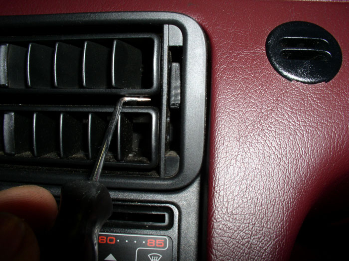
Next, remove the center vent deflector vanes. I found a 90 degree pick tool to work well here. Just catch the inside of the vane unit as shown and pull outward on one side followed by the other side.
continued.......
After removing the console side panel, you will notice the hard plastic vacuum hoses in multiple colors that feed the various vacuum actuators of the HVAC system. These will be described in a moment.
You have a couple of options here to conduct the next test. You will notice you can't access all of the vacuum hose connections at the solenoid. In fact, I could only access the last one (yellow, pictured below) to pull the vacuum line and test with the MightyVac. You can cut each of the hard lines and attach the MightyVac to the end of the hose that runs up into the dash. If everything checks out, you can simply re-connect the severed connection with a rubber vacuum hose coupling. The other option you have is to remove the vacuum solenoid console (which is what I did) so you can access all the vacuum line connections at the solenoids and test the lines without cutting. I discovered here that my yellow line (goes to the footwell flap vacuum actuator) had a leak so I was going to have to remove the center console anyway to repair it. I might as well remove the solenoid console to test the rest of the actuators for leaks.
Next, remove the brace that holds the under dash tray. It's held on by a 10mm nut.
Going over to the passenger side, remove the underdash tray and center console cover as you did on the driver's side. One difference you will notice is the passenger side underdash tray has a lamp monitor attached to the outer end of the tray (near the car door). You can either disconnect the electrical harness or remove the monitor box from the tray with the two mounting bolts in order to remove the tray.
Remove the center console side cover.
You will find a phillips screw that holds the solenoid console protective cover in place (see pic). Remove the phillips screw.
You will find the same screw on the driver's side. Remove it as well.
Once the screws are removed, the cover will drop down. The solenoid console is held in place by one final phillips screw in the center of the mounting bracket (see arrow in pic). There isn't much room to remove this screw.....
....In order to gain a little more working room, I pulled out the vacuum solenoid console cover as shown.....
....and pulled out the radio a few inches. In order to pull out the radio, you will need the installation "keys" to pull the radio (your radio will differ). Since I was going to have to remove the radio as part of the console removal process anyway, this seemed like a reasonable thing to do.
With a little more room to work with, I used a 90 degree phillips screwdriver to get the screw out. A stubby phillips screwdriver works well here too.
With the center screw removed, you can pull out the solenoid console out the driver's side as shown. There is one vacuum source line (black) and 5 output lines - one from each solenoid. They are marked in the pic below as to what function each color line performs and the location of the vacuum actuator. Yellow goes to the footwell flap, green goes to the defrost flap, orange goes to the comb flap, white goes to the hot water control valve, and blue goes to the recirculation flap.
You can test each line one at a time by disconnecting the line from the solenoid and attaching the mightyvac to the rubber hose connection. I applied about 15 inches HG and listened for the flap movement and watched the vacuum gauge to see if it would hold vacuum. If everything checked out, I reconnected the line and move to the next. I found that I had a leak in the Yellow (footwell flap) and the orange (comb flap) lines. The rest of the lines all held vacuum and operated the flaps. For me, the next steps would be to remove the center console to get at the to leaking actuators. If you find that you have a leaking defroster actuator, you will need to remove the instrumentation pod to get to it. If the hot water control valve is leaking vacuum, you will need to remove the air filter box in the engine bay in order to get at the actuator. If you have a leak in the recirculation flap, you will need to remove the fan blower motor and recirculation box above the CEB to get at the actuator.
If you have tested all the vacuum lines to their respective actuators and did not find a leak, then the leak is most likely in one of the vacuum solenoids. There are 5 solenoids and any one or all may be leaking vacuum. Even if you found a leak at one of the actuators, it's a good idea to test the solenoids as well - and now is the perfect time. The quick and easy way to test all the solenoids at once is to hook up the mighty vac to the rubber vacuum manifold where the source vacuum line (black line) comes in. Disconnect all the vacuum lines that go to the actuators and cap the vacuum port at the solenoid with a vacuum cap as shown below. Pump up the vacuum to about 15 inches Hg and turn the ignition switch to "run". If the vacuum does not hold, then you have a leak in one or more of the solenoids. When I checked Virginia (87) during this procedure, all solenoids were good and vacuum tight. However, when I performed this test on California ('84), 4 out of the 5 solenoids leaked vacuum. So I ordered 4 used ones from 928 Intl and now they are all working. To pinpoint the leaking solenoid, remove the rubber vacuum manifold and plug the mighty vac directly into each input port of each solenoid (one at a time) and pump up the vacuum, turn on the ignition to "run" and see if it will hold vacuum. Operate the bottom slider **** on the A/C control unit to energize the different solenoids. I found my old solenoids would hold vacuum when the ignition was off but would leak when power was applied. If you find a leaking solenoid, they are easy to replace: remove the electrical wire and remove the phillips screw on the bottom of the solenoid mounting plate and the solenoid is free to be replaced.
Before proceeding with removing the center console, I recommend you disconnect the negative terminal to the battery since you will be disconnecting several wiring harnesses.
To remove the center console: Finish removing the radio by disconnecting the wiring harness, antenna and ground wires from the rear of the radio and remove the radio unit.
Next, remove the center vent deflector vanes. I found a 90 degree pick tool to work well here. Just catch the inside of the vane unit as shown and pull outward on one side followed by the other side.
continued.......
Last edited by Dwayne; 02-28-2009 at 07:19 PM.
02-26-2009, 01:04 AM
#7
Rennlist Member
Thread Starter
Join Date: Sep 2007
Location: Ridgecrest, California
Posts: 1,363
Likes: 0
Received 143 Likes
on
28 Posts
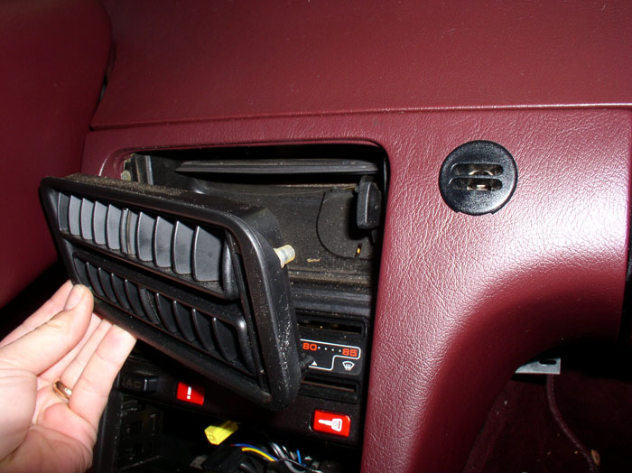
With both sides free, you can remove the center vent deflector vanes.
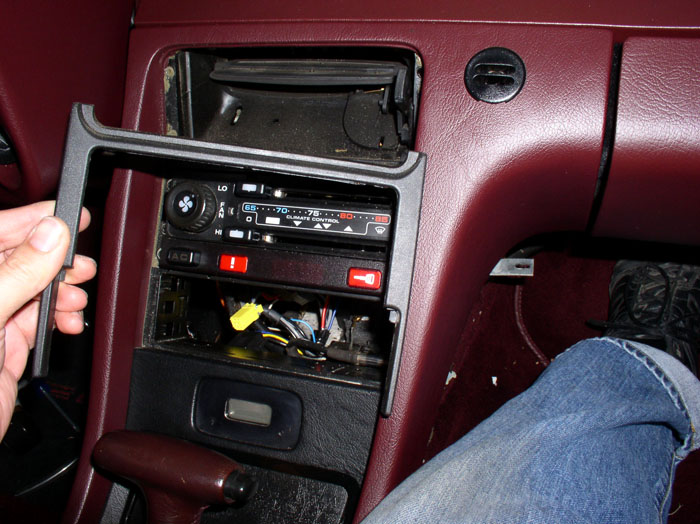
Next, remove the A/C control unit/radio trim piece. I used the same 90 degree pick tool. I pushed up slightly (toward the center vent) and pulled out using the pick tool at the same time.
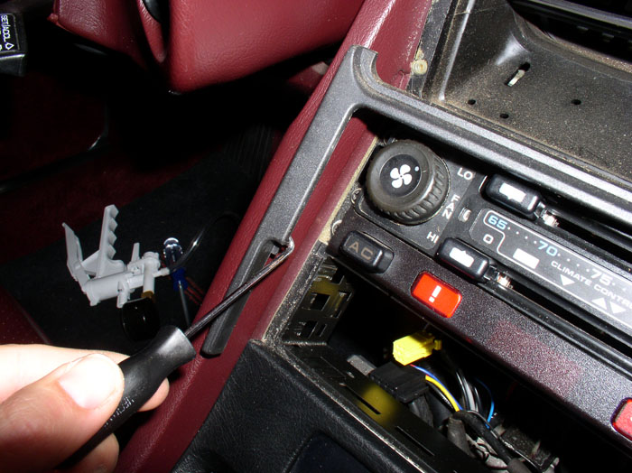
It's a tight fit but with a little care and patience, it will come out undamaged.
The A/C control unit is held in place with four phillips screws (2 on each side). The A/C switch and warning strip is held in place with two phillips screws (1 on each side). Remove all 6 of these screws.
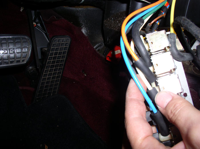
Next, disconnect the wiring harness plug from the back of the A/C switch.
Then disconnect the 6-wire and 4-wire wiring harness connectors that are attached to the warning strip.....
....and remove the warning strip.
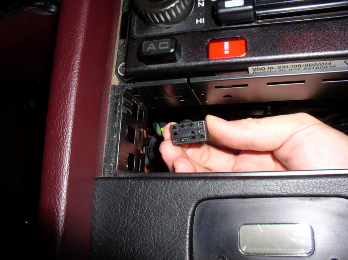
Next, pull out the A/C control unit. You will notice two wiring harness connections (see arrows).
You can pry off the front harness connection.....
....and pull off the rear harness connection.
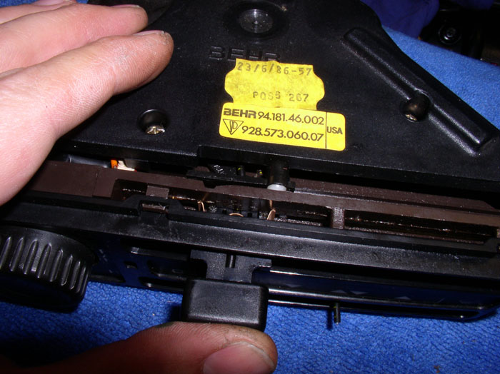
Then, remove the A/C control unit.
My control unit had broken slider ***** as shown here. I will be repairing these later in this post.
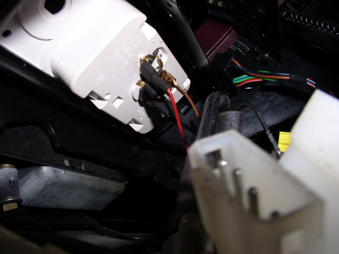
Next, disconnect the wires at the back of the clock. Note the color of the wires and the terminal the wire is connected to for re-installation.
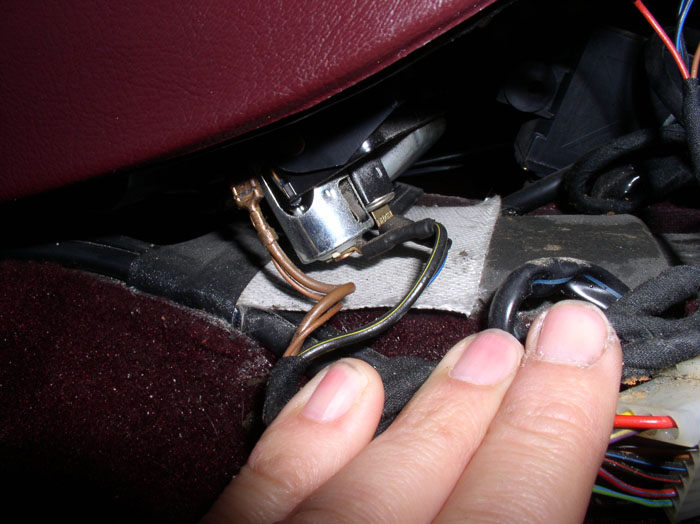
Then, disconnect the wires at the back of the cigarette lighter. Note the color of the wires and the terminal they are connected to. There is a black wire with yellow stripe and a black wire with a blue stripe and a pair of ground wires.
Next, remove the two 8-mm bolts at the top of the center vent. One on the driver's side here as shown.
continued......
Next, remove the A/C control unit/radio trim piece. I used the same 90 degree pick tool. I pushed up slightly (toward the center vent) and pulled out using the pick tool at the same time.
It's a tight fit but with a little care and patience, it will come out undamaged.
The A/C control unit is held in place with four phillips screws (2 on each side). The A/C switch and warning strip is held in place with two phillips screws (1 on each side). Remove all 6 of these screws.
Next, disconnect the wiring harness plug from the back of the A/C switch.
Then disconnect the 6-wire and 4-wire wiring harness connectors that are attached to the warning strip.....
....and remove the warning strip.
Next, pull out the A/C control unit. You will notice two wiring harness connections (see arrows).
You can pry off the front harness connection.....
....and pull off the rear harness connection.
Then, remove the A/C control unit.
My control unit had broken slider ***** as shown here. I will be repairing these later in this post.
Next, disconnect the wires at the back of the clock. Note the color of the wires and the terminal the wire is connected to for re-installation.
Then, disconnect the wires at the back of the cigarette lighter. Note the color of the wires and the terminal they are connected to. There is a black wire with yellow stripe and a black wire with a blue stripe and a pair of ground wires.
Next, remove the two 8-mm bolts at the top of the center vent. One on the driver's side here as shown.
continued......
Trending Topics
02-26-2009, 01:27 AM
#8
Rennlist Member
Thread Starter
Join Date: Sep 2007
Location: Ridgecrest, California
Posts: 1,363
Likes: 0
Received 143 Likes
on
28 Posts
I used a combination wrench to get at the 8mm bolt on the passenger side.
Next, remove the two phillips screws under the dash on the driver's side that hold the center console to the dash.
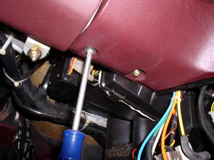
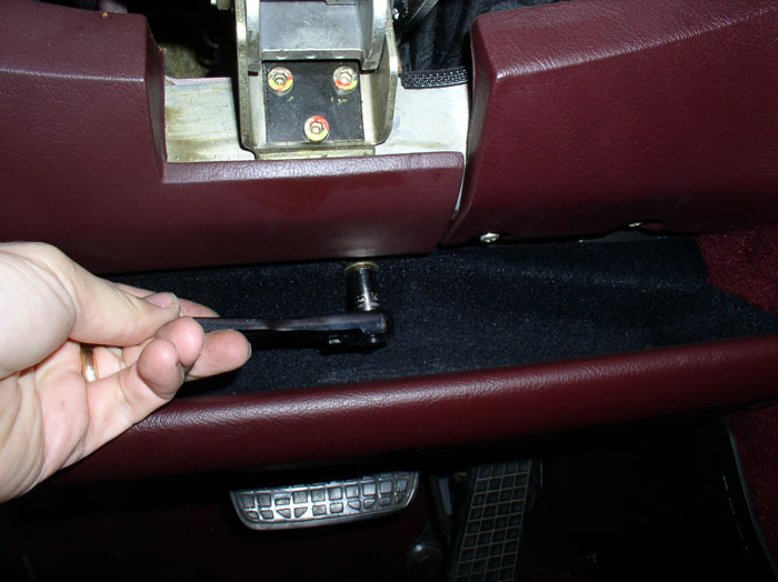
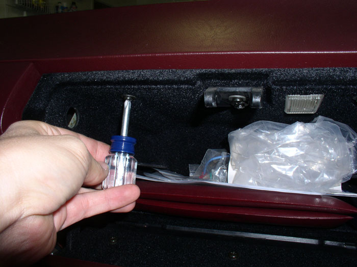
Remove the cover plug inside the glove box as shown.
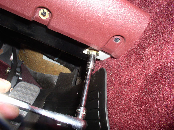
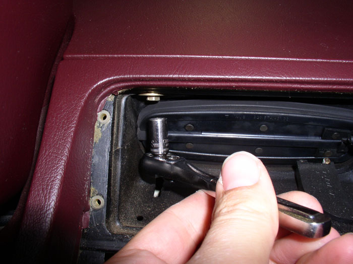
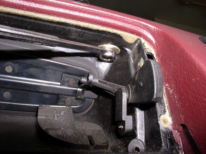
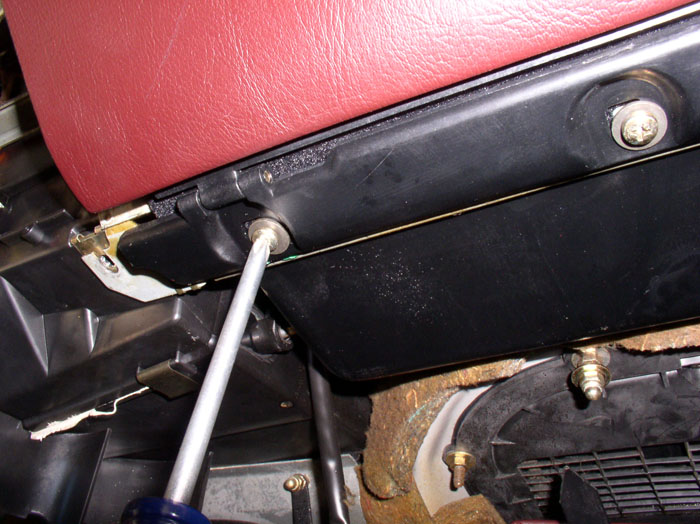
Loosen the 8mm hex head screw with a socket and extension as shown.
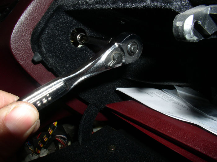
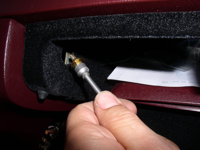
When the screw is loosened, you can use a magnetic pick up tool to pull the screw out.
Remove the two phillips screws under the dash on the passenger side as shown.
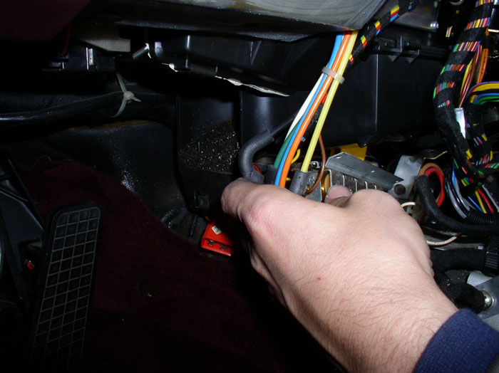
Disconnect the rear wiper switch harness.
Disconnect the passenger side window switch wiring harness. This '87 did not have a sunroof so no sunroof harness to disconnect. If you have a sunroof, you will need to disconnect that harness connector as well.
Clip the harness tie down.
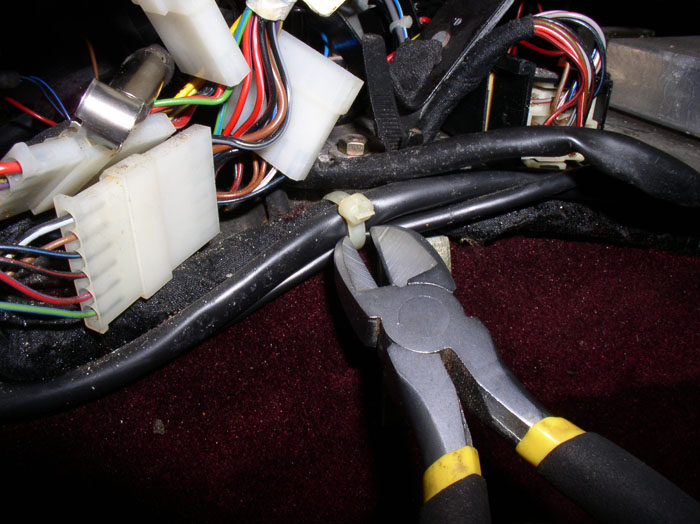
And remove the harness from the tape as shown.
Pull out the wiring harnesses so they are free of any entanglements,
Next, disconnect the driver's side window switch wiring harness.
Remove the harness from the tape as shown.
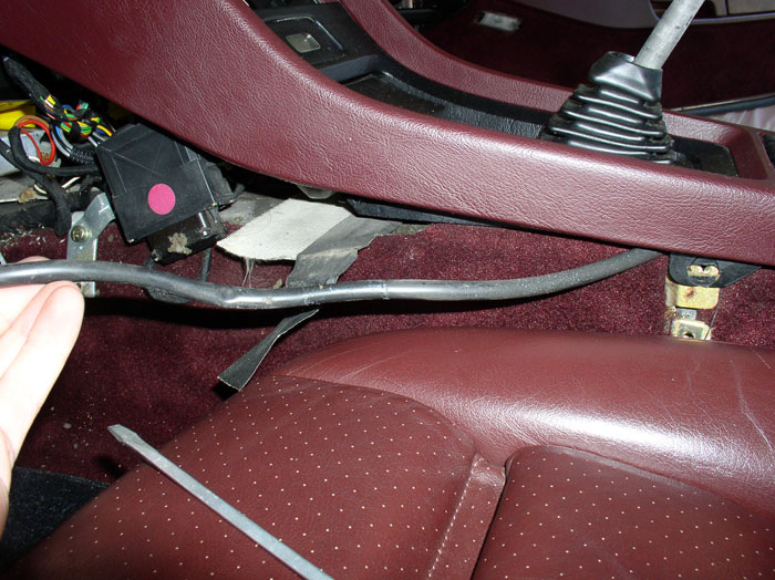
Remove the two phillips screws that secure the rear of the center console. There's one screw on each driver's/passenger's side.
For automatics, you will need to lower the shift handle all the way down to "2". For Manuals, you will need to place the shifter in neutral.
continued......
Next, remove the two phillips screws under the dash on the driver's side that hold the center console to the dash.
Remove the cover plug inside the glove box as shown.
Loosen the 8mm hex head screw with a socket and extension as shown.
When the screw is loosened, you can use a magnetic pick up tool to pull the screw out.
Remove the two phillips screws under the dash on the passenger side as shown.
Disconnect the rear wiper switch harness.
Disconnect the passenger side window switch wiring harness. This '87 did not have a sunroof so no sunroof harness to disconnect. If you have a sunroof, you will need to disconnect that harness connector as well.
Clip the harness tie down.
And remove the harness from the tape as shown.
Pull out the wiring harnesses so they are free of any entanglements,
Next, disconnect the driver's side window switch wiring harness.
Remove the harness from the tape as shown.
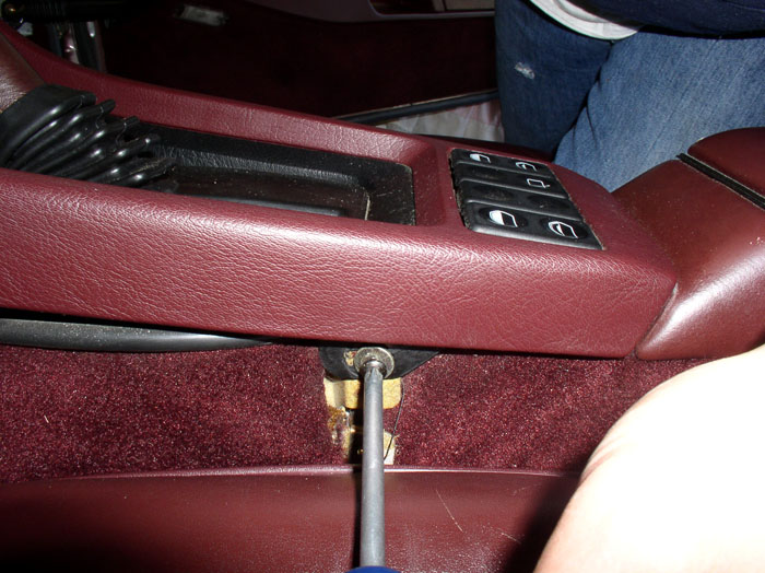
Remove the two phillips screws that secure the rear of the center console. There's one screw on each driver's/passenger's side.
For automatics, you will need to lower the shift handle all the way down to "2". For Manuals, you will need to place the shifter in neutral.
continued......
02-26-2009, 02:02 AM
#9
Rennlist Member
Thread Starter
Join Date: Sep 2007
Location: Ridgecrest, California
Posts: 1,363
Likes: 0
Received 143 Likes
on
28 Posts
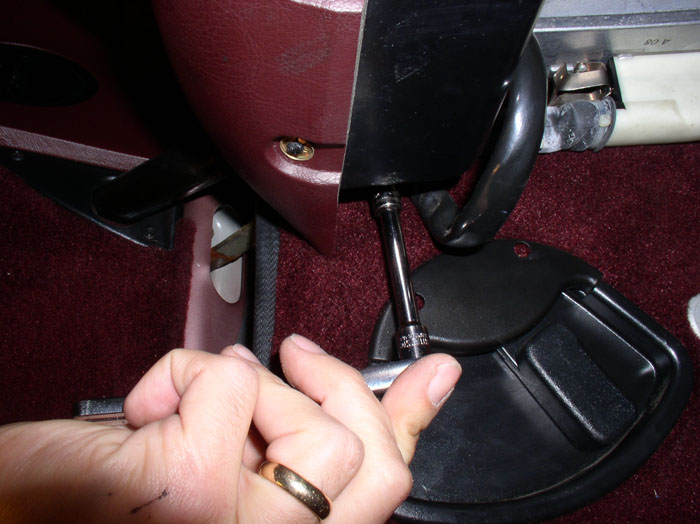
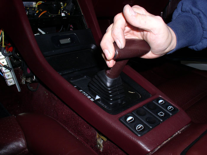
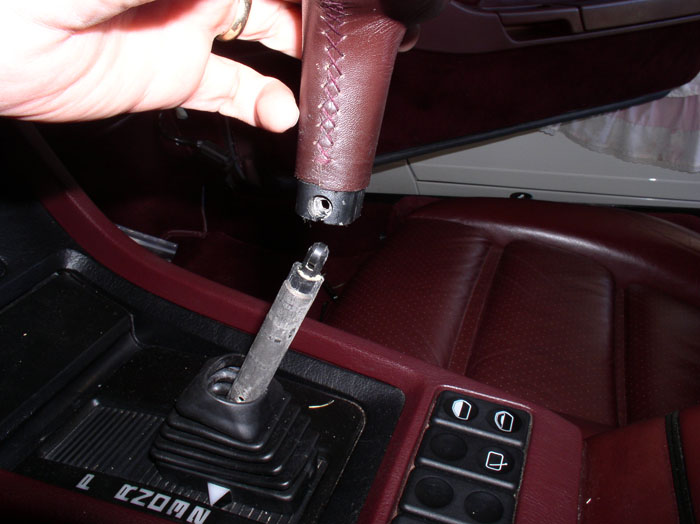
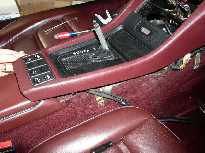
Next, remove the shift handle. Pull down the shifter boot to expose the handle mounting screws and remove. There's one on each side of the handle. Unfortunately, mine had one flat blade screw and one phillips screw so I'm not sure which was original. For manual, you will need to remove the top of the shift stick.
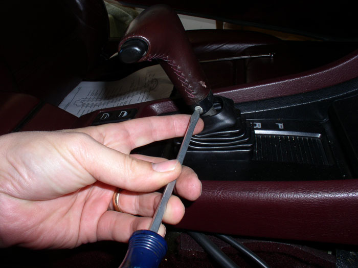
Remove the handle by lifting straight up.
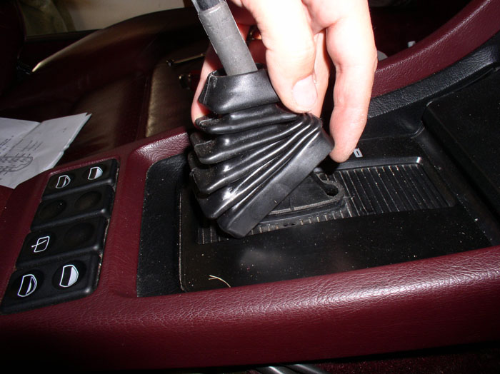
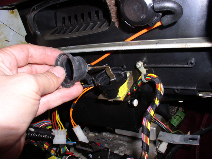
Remove the boot by pulling the base way from the groove in the shift plate and lifting up over the shift lever.
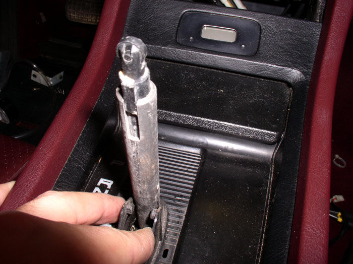
Disconnect the shift plate from the shift lever by slightly prying the notched tabs out away from the shift lever as shown.
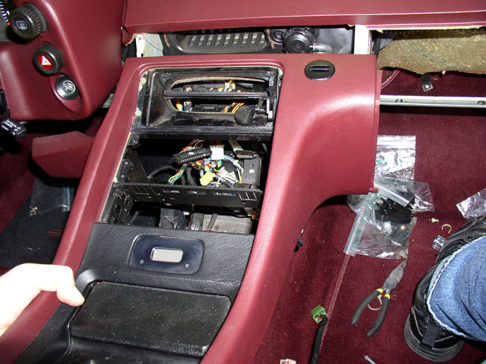
Next, pull back on the cener console a few inches.
Lift up at the rear of the console.....
....while pulling back toward the rear of the car.
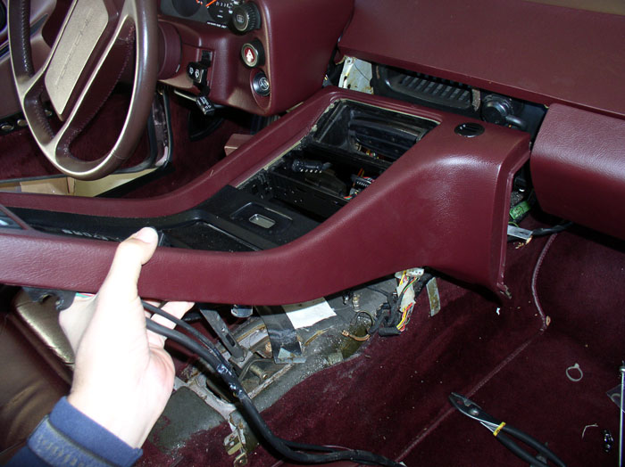
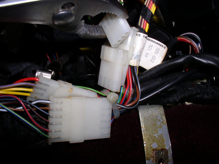
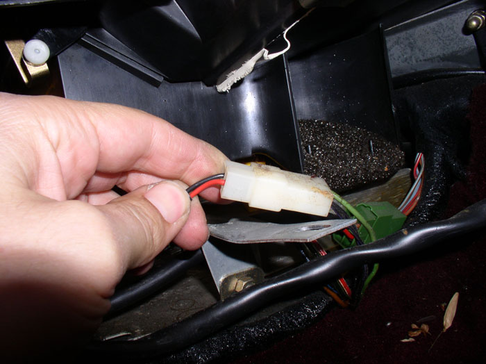
There are two more wiring harness connectors to disconnect. These go to the shift plate. Disconnect these wires (a 2-wire plug and a 4-wire plug). Then remove the console.
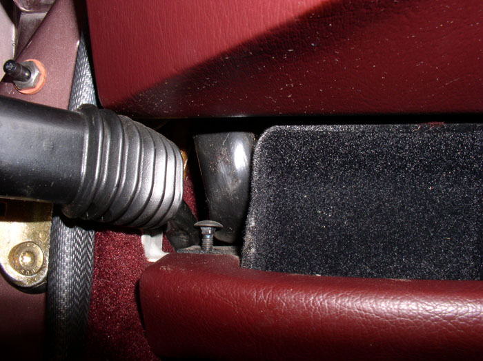
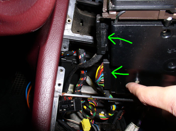
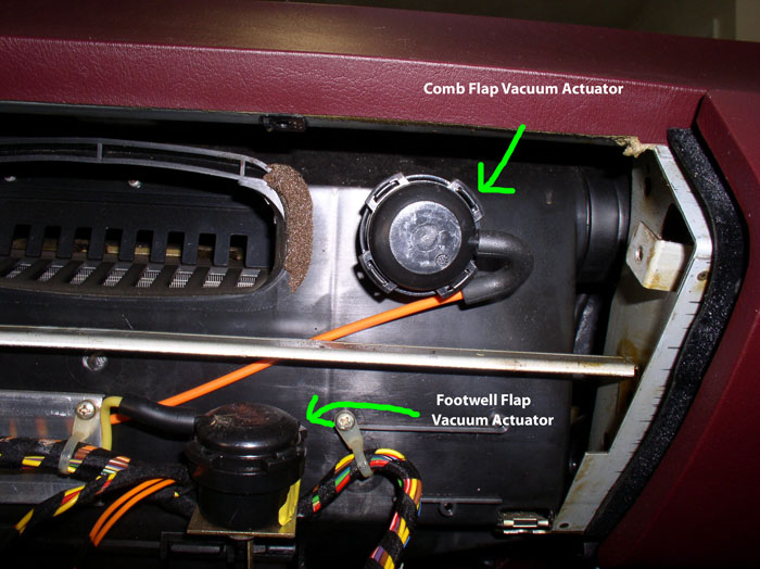
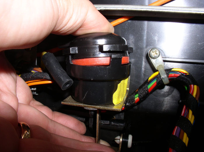
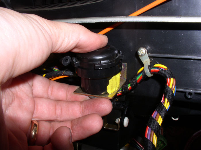
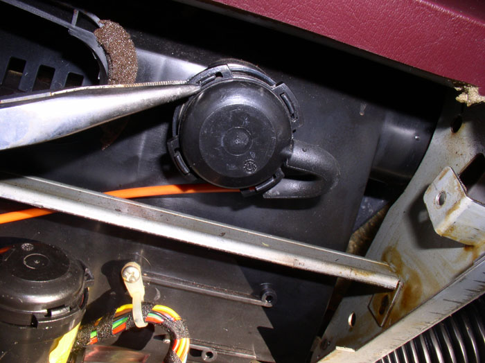
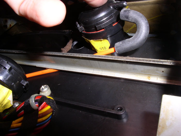
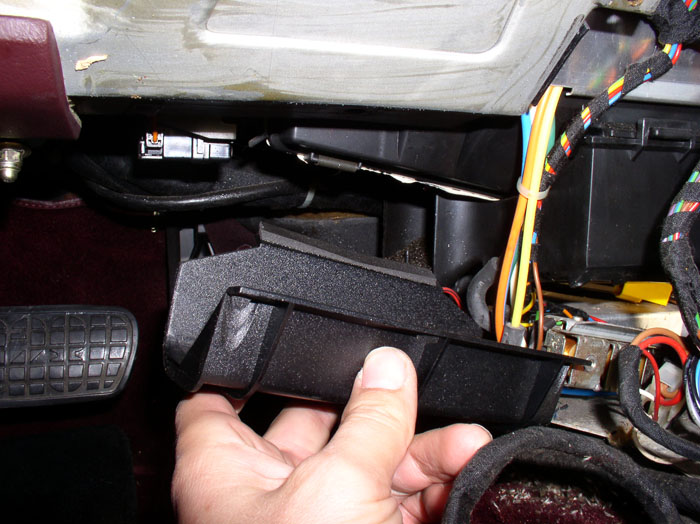
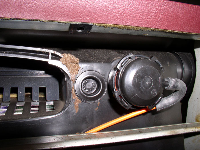
The footwell flap vacuum actuator and comb flap vacuum actuator will now be exposed as shown by the arrows. Inspect the vacuum hose connections for leaks. If it's solidly connected, and the hose is not damaged, the vacuum diaphram inside the housing is in need of repair.
Start with the footwell actuator by disconnecting the yellow vacuum line.

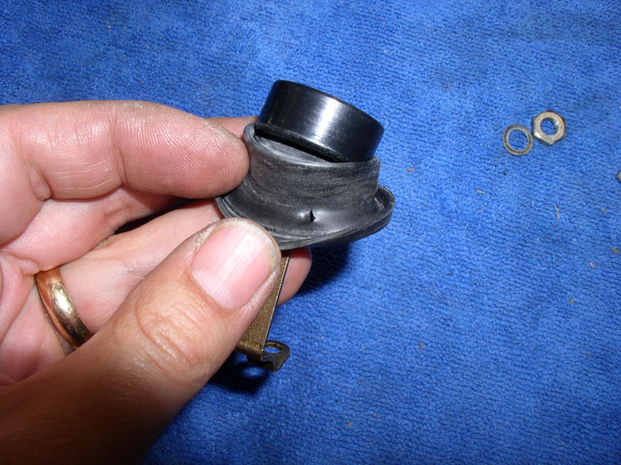
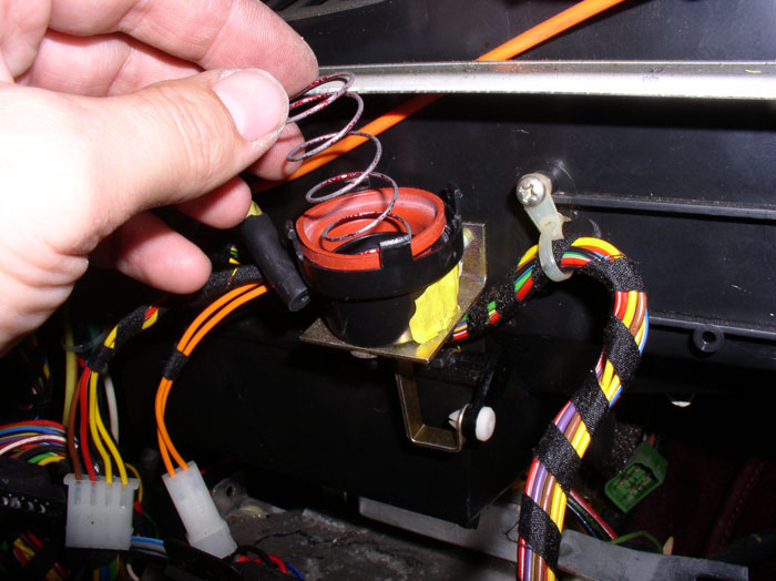
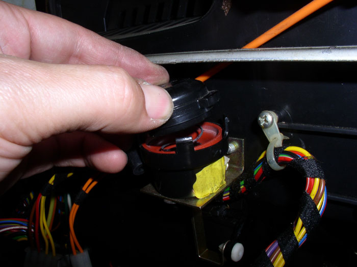
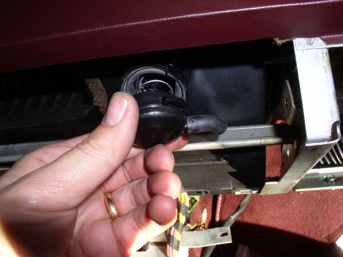
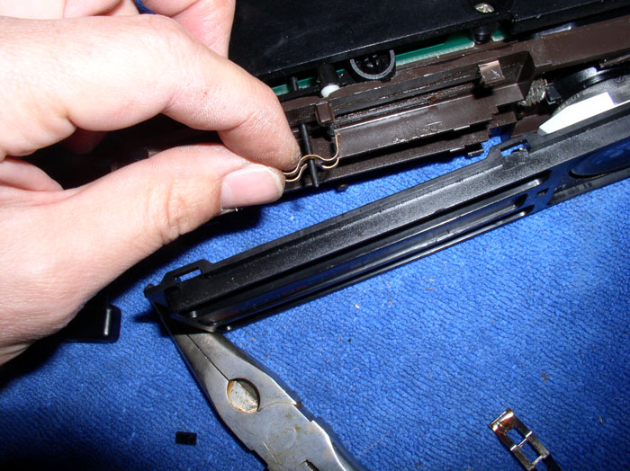
You can repair the diaphram with the actuator housing in place. We need to remove the cap and disconnect the lever arm in order to remove the diaphram. To remove the top, depress the locking tabs on the top (4 of them). I used a pair of needle nose pliers as shown.
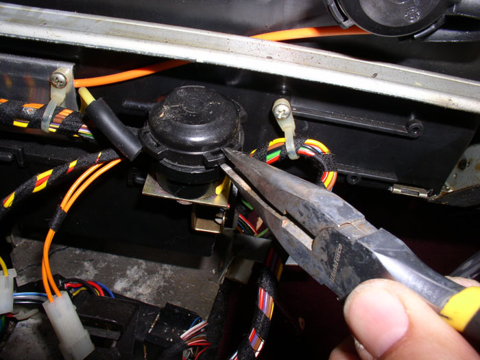
When the tabs are released, the top will come off - be careful to hold the top in place as you release the tabs because the top is under spring load. Remove the top.
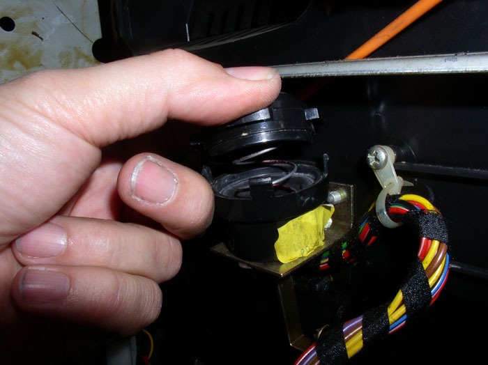
Remove the spring noting the orientation, small end on the diphram and large end against the top as shown.
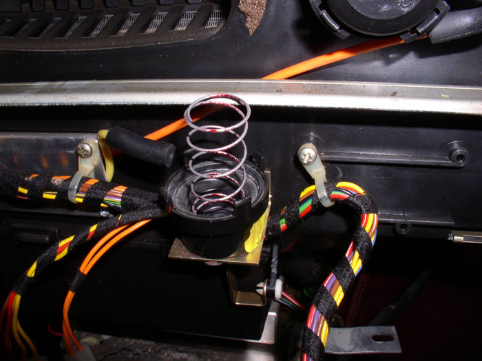
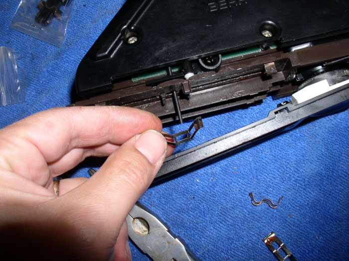
Next, use a small screwdriver to pry the plastic lock pin out just enough to release the metal actuator lever arm.
With the lever arm free, bend the arm just enough to allow you to manuever the diaphram and lever arm out of the plastic housing. Don't worry, you will be able to easily bend it back to it's original shape.
continued......
Remove the handle by lifting straight up.
Remove the boot by pulling the base way from the groove in the shift plate and lifting up over the shift lever.
Disconnect the shift plate from the shift lever by slightly prying the notched tabs out away from the shift lever as shown.
Next, pull back on the cener console a few inches.
Lift up at the rear of the console.....
....while pulling back toward the rear of the car.
There are two more wiring harness connectors to disconnect. These go to the shift plate. Disconnect these wires (a 2-wire plug and a 4-wire plug). Then remove the console.
The footwell flap vacuum actuator and comb flap vacuum actuator will now be exposed as shown by the arrows. Inspect the vacuum hose connections for leaks. If it's solidly connected, and the hose is not damaged, the vacuum diaphram inside the housing is in need of repair.
Start with the footwell actuator by disconnecting the yellow vacuum line.
You can repair the diaphram with the actuator housing in place. We need to remove the cap and disconnect the lever arm in order to remove the diaphram. To remove the top, depress the locking tabs on the top (4 of them). I used a pair of needle nose pliers as shown.
When the tabs are released, the top will come off - be careful to hold the top in place as you release the tabs because the top is under spring load. Remove the top.
Remove the spring noting the orientation, small end on the diphram and large end against the top as shown.
Next, use a small screwdriver to pry the plastic lock pin out just enough to release the metal actuator lever arm.
With the lever arm free, bend the arm just enough to allow you to manuever the diaphram and lever arm out of the plastic housing. Don't worry, you will be able to easily bend it back to it's original shape.
continued......
02-26-2009, 11:40 PM
#10
Rennlist Member
Thread Starter
Join Date: Sep 2007
Location: Ridgecrest, California
Posts: 1,363
Likes: 0
Received 143 Likes
on
28 Posts
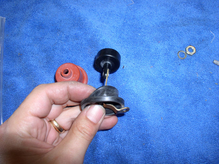
Now you can simply lift out the vacuum diaphram as shown.
Here's the diaphram and lever arm removed and the new diaphram from Roger.
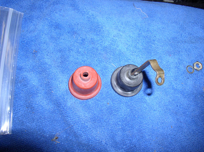
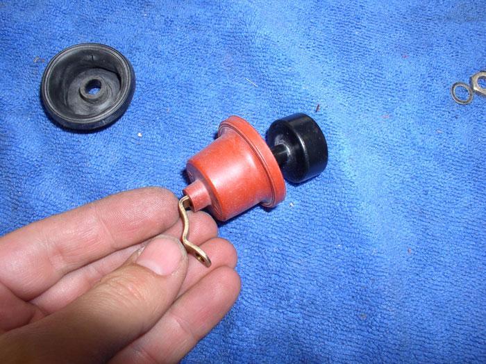
You remove the old diaphram by pulling it back over the lever arm as shown. Notice the small split in the diaphram that was causing the leak.
Continue pulling off the diaphram until completely removed.
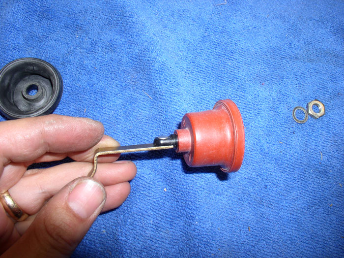
Insert the new diaphram onto the lever arm oriented the same direction as the old diaphram (as shown).
When the new diaphram is fully seated on the lever arm, it should look like this.
Next, place the end of the lever arm back through the bottom of the vacuum container as shown.
Using pliers, bend the end of the lever arm back to it's original configuration.....
....it should look something like this.
Next, reattach the lock pin at the end of the lever arm.
Install the spring with wide opening facing up.
Install the cap oriented in the same manner as it came off.
Ensure the diaphram is sealed properly all around on the top and bottom rims of the vacuum container (i.e., not pinched or distorted)
Snap the top of the vacuum container into place ensuring all four tabs lock.
Re-attach the vacuum hose.
continued.....
Here's the diaphram and lever arm removed and the new diaphram from Roger.
You remove the old diaphram by pulling it back over the lever arm as shown. Notice the small split in the diaphram that was causing the leak.
Continue pulling off the diaphram until completely removed.
Insert the new diaphram onto the lever arm oriented the same direction as the old diaphram (as shown).
When the new diaphram is fully seated on the lever arm, it should look like this.
Next, place the end of the lever arm back through the bottom of the vacuum container as shown.
Using pliers, bend the end of the lever arm back to it's original configuration.....
....it should look something like this.
Next, reattach the lock pin at the end of the lever arm.
Install the spring with wide opening facing up.
Install the cap oriented in the same manner as it came off.
Ensure the diaphram is sealed properly all around on the top and bottom rims of the vacuum container (i.e., not pinched or distorted)
Snap the top of the vacuum container into place ensuring all four tabs lock.
Re-attach the vacuum hose.
continued.....
02-27-2009, 12:15 AM
#11
Rennlist Member
Thread Starter
Join Date: Sep 2007
Location: Ridgecrest, California
Posts: 1,363
Likes: 0
Received 143 Likes
on
28 Posts
Next, test the new diaphram for operation and leaks. Disconnect the yellow vacuum line from the solenoid console (if not already disconnected) and attach the mightyvac. Not the at rest position of the lever arm.
Pump up the vacuum and watch for movement of the lever arm.
Note the vacuum required to "bottom out" the lever arm and wait to see if the vacuum holds. In this case everything is working fine.
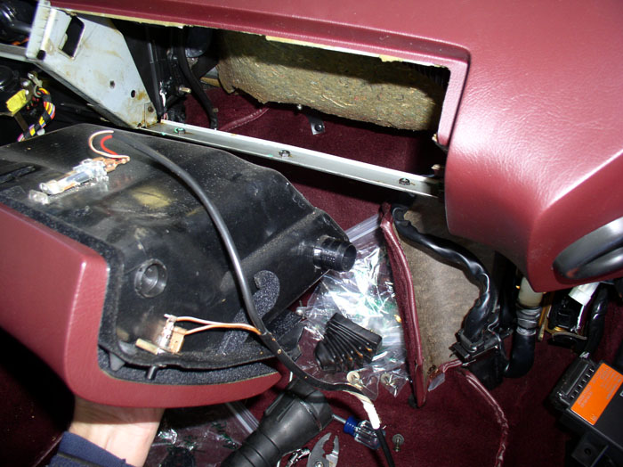
Next, I needed to work on the Comb flap diaphram. In order to "re-connect" the lever arm on this actuator, it was easier to remove the glove box to gain access to the lever arm connection. I went ahead and removed the glove box now. Start by removing the two phillips screws that hold the upper portion of the box to the dash (one on the left and one on the right).
Then remove the 3 phillips screws underneath the glove box door at the hinge as shown.
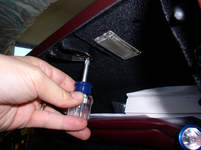
Next, remove the latch by removing the two phillips screws that attach the latch to the top of the glove box as shown.
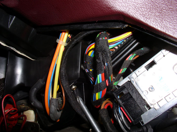
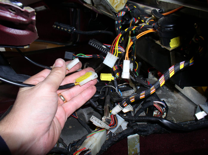
Then locate the glove box light harness connection. It's located above and behind the EZK and LH computers. The wires should be held in place by a wire strap as shown.
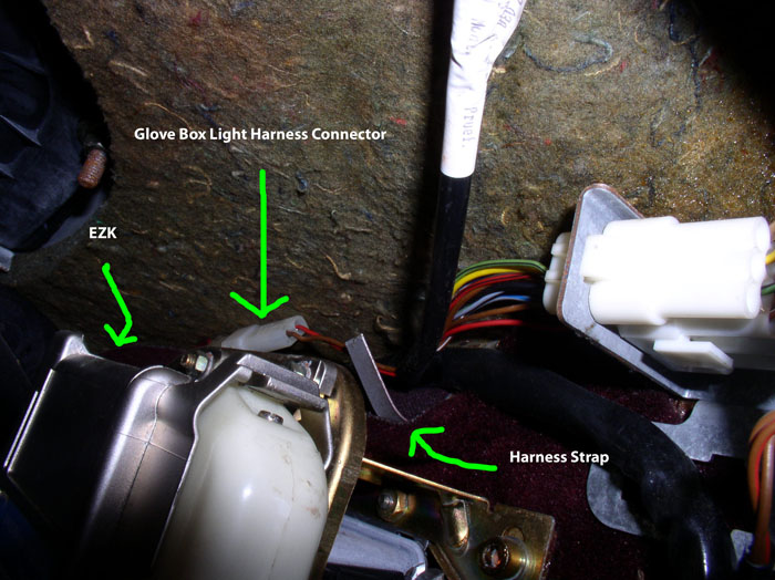
Disconnect the wire harness and remove the wire from the hold down strap.
Pull the glove box out enough to see the vent hose connection and disconnect the vent hose from the glove box.
Now, you can remove the glove box.
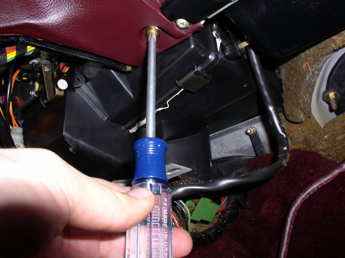
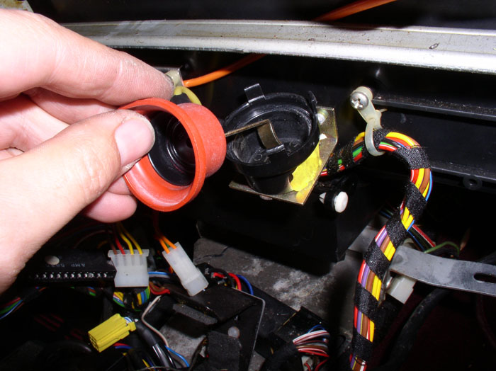
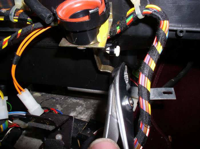
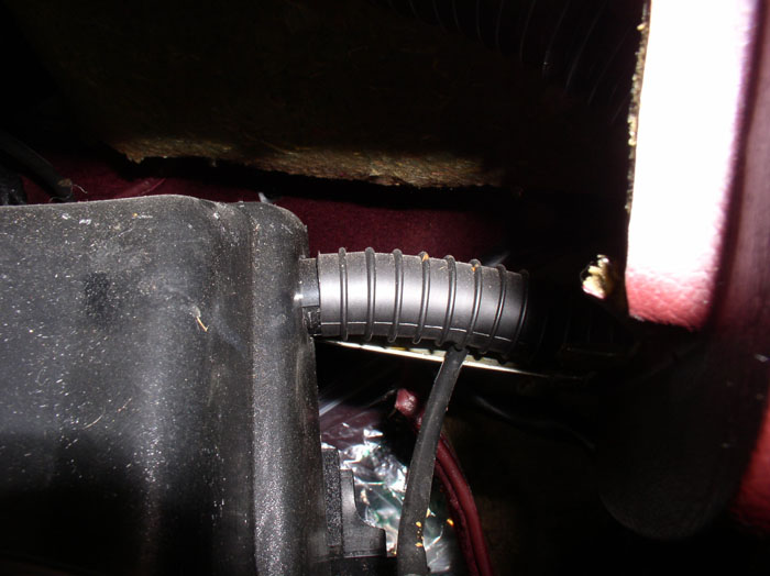
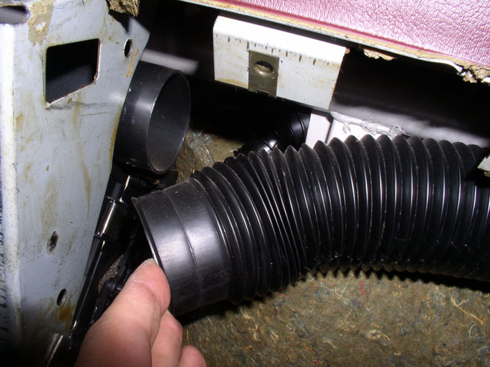
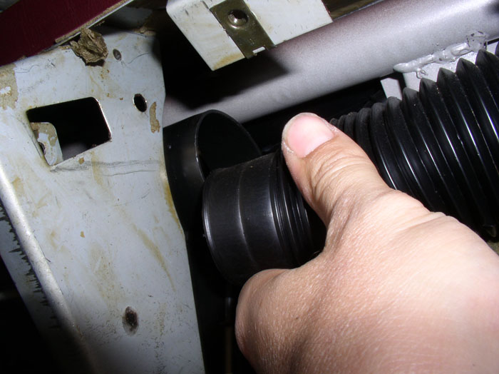
Next, disconnect the HVAC hose from the air distribution box as shown. This will give you access to the comb flap actuator arm connection inside the air distribution box. You can view the connection using a flashlight or snakelight. Access from this angle was particularly handy for re-connecting the lever arm to the flap when I was re-installing the new diaphram.
Back to removing the old diaphram. Press back the plastic tabs on the vacuum container lid as you did on the footwell vacuum container remembering the lid is spring loaded.
Remove the lid and the spring.
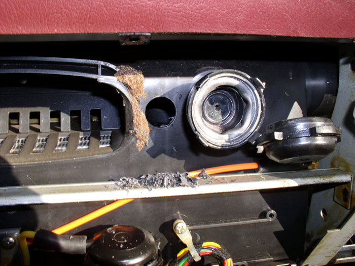
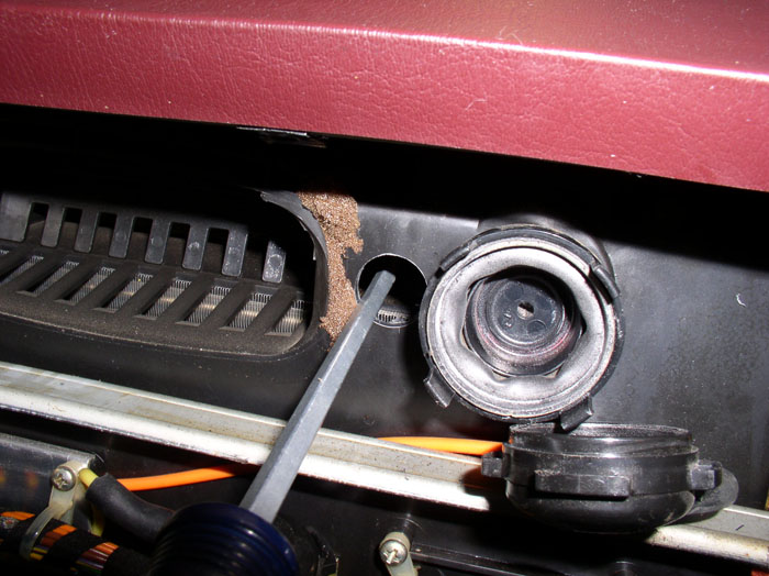
At this point, there are a couple of methods for disconnecting the vacuum lever arm at the flap lever arm (the connection is inside the air distribution box). The connection is similar to the lock pin connection you just dealt with on the footwell vacuum lever arm above. I believe the easiest method is to simply rotate the diaphram/lever arm and the arm will "pop" off the lock pin at the connection to the comb flap. Then extract the vacuum lever arm as described in a few pictures from here (THANKS to "Aryan" and "Xlot" for this tip!). The other method, the one I followed and documented here, is to drill a hole in the distribution box big enough to insert a screwdriver to "pop" the lock pin connection. This method is more work and will require a body plug to be installed to plug the hole in the air distribution box. I drilled a 3/4" hole in the air distribution box right between the vent and the comb flap vacuum container.
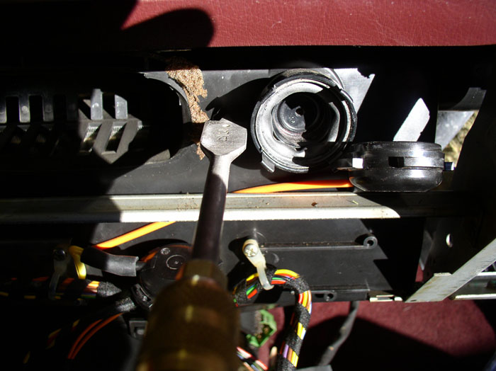
After the hole is drilled, you will be able to view the connection of the vacuum lever arm to the comb flap.
continued.......
Pump up the vacuum and watch for movement of the lever arm.
Note the vacuum required to "bottom out" the lever arm and wait to see if the vacuum holds. In this case everything is working fine.
Next, I needed to work on the Comb flap diaphram. In order to "re-connect" the lever arm on this actuator, it was easier to remove the glove box to gain access to the lever arm connection. I went ahead and removed the glove box now. Start by removing the two phillips screws that hold the upper portion of the box to the dash (one on the left and one on the right).
Then remove the 3 phillips screws underneath the glove box door at the hinge as shown.
Next, remove the latch by removing the two phillips screws that attach the latch to the top of the glove box as shown.
Then locate the glove box light harness connection. It's located above and behind the EZK and LH computers. The wires should be held in place by a wire strap as shown.
Disconnect the wire harness and remove the wire from the hold down strap.
Pull the glove box out enough to see the vent hose connection and disconnect the vent hose from the glove box.
Now, you can remove the glove box.
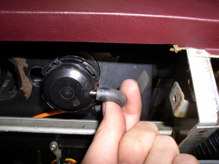
Next, disconnect the HVAC hose from the air distribution box as shown. This will give you access to the comb flap actuator arm connection inside the air distribution box. You can view the connection using a flashlight or snakelight. Access from this angle was particularly handy for re-connecting the lever arm to the flap when I was re-installing the new diaphram.
Back to removing the old diaphram. Press back the plastic tabs on the vacuum container lid as you did on the footwell vacuum container remembering the lid is spring loaded.
Remove the lid and the spring.
At this point, there are a couple of methods for disconnecting the vacuum lever arm at the flap lever arm (the connection is inside the air distribution box). The connection is similar to the lock pin connection you just dealt with on the footwell vacuum lever arm above. I believe the easiest method is to simply rotate the diaphram/lever arm and the arm will "pop" off the lock pin at the connection to the comb flap. Then extract the vacuum lever arm as described in a few pictures from here (THANKS to "Aryan" and "Xlot" for this tip!). The other method, the one I followed and documented here, is to drill a hole in the distribution box big enough to insert a screwdriver to "pop" the lock pin connection. This method is more work and will require a body plug to be installed to plug the hole in the air distribution box. I drilled a 3/4" hole in the air distribution box right between the vent and the comb flap vacuum container.
After the hole is drilled, you will be able to view the connection of the vacuum lever arm to the comb flap.
continued.......
Last edited by Dwayne; 02-28-2009 at 10:56 AM.
02-27-2009, 12:47 AM
#12
Rennlist Member
Thread Starter
Join Date: Sep 2007
Location: Ridgecrest, California
Posts: 1,363
Likes: 0
Received 143 Likes
on
28 Posts
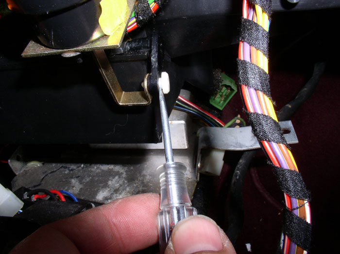
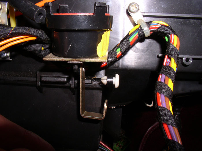
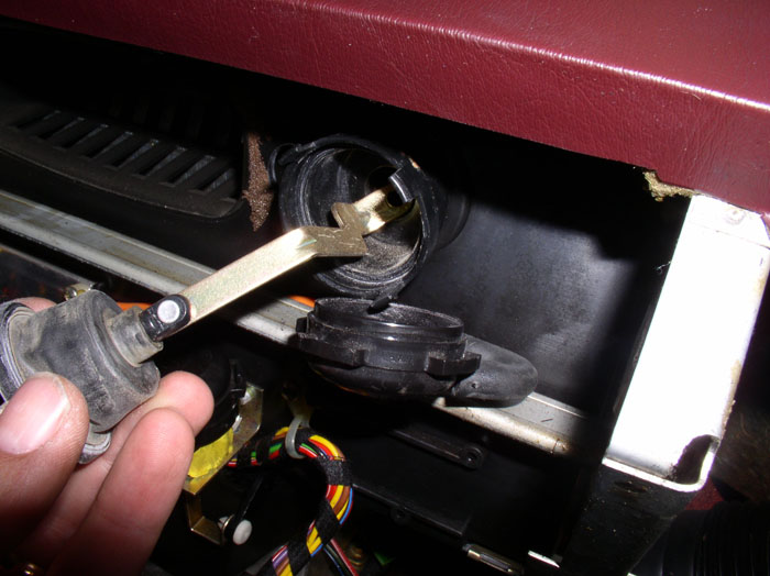
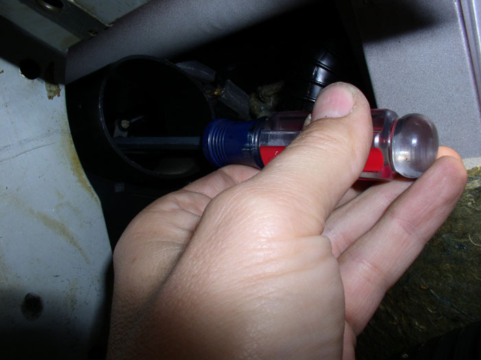
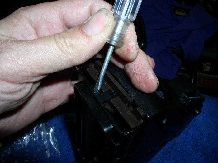
Using this method, I found it very easy to disconnect the vacuum lever arm from the comb flap by using a flat blade screwdriver. Insert the screwdriver between the lock pin and lever arm and twist and it will pop right off.
You can then pull out the diaphram and lever arm as shown.
Replace the diaphram as described earlier on the footwell diaphram.
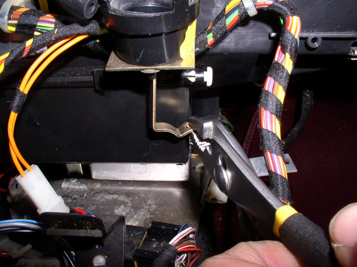
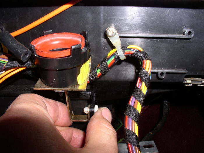
Re-insert the lever arm back into the air distribution box as shown.
Re-connect the diaphram lever arm to the comb flap by entering the air box from the port behind the glove box. Line up the pin and press on the connection with the screwdriver until the lock pin clicks into place. If needed, you can counterhold the lever arm through the front 3/4" hole we cut earlier using another screwdriver.
Position the spring with larger opening facing out.
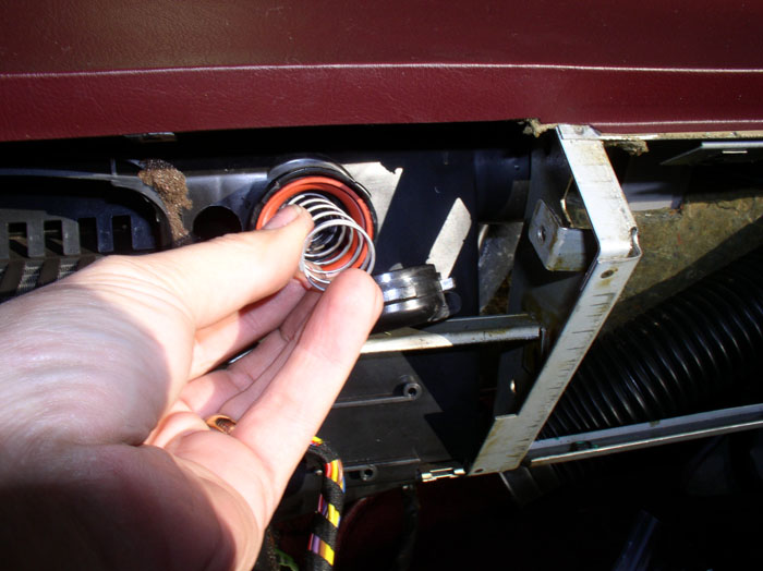
Position the lid ensuring the diaphram is properly seated on the lid and bottom rims of the vacuum container.
Snap the lid into place ensuring all four tabs lock into place and re-connect the vacuum hose to the vacuum lid.
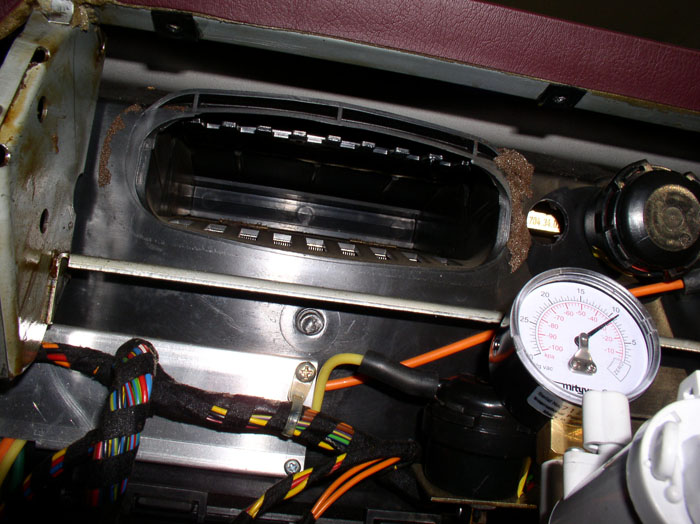
Connect the mightyvac to the other end of the orange vaccum line (at the solenoid console) and note the position of the comb flap at rest.
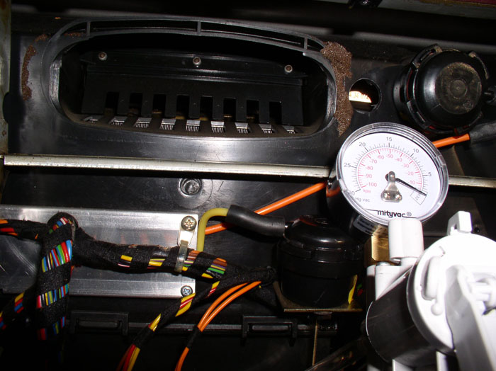
Pump up the vacuum and watch the comb flap move up - it should move freely.

Note when the comb flap reaches maximum and the note the vacuum level. Then watch the gauge to confirm it holds vacuum. Everything checked out OK here!
Now you're done with the footwell and comb flap diaphram repair and you can begin reassembling the center console. First, reconnect any disconnected vacuum lines at the solenoid console and ensure all hoses are fully seated.
Next, slide the vacuum solenoid console back into position in the center console.
Slide the vacuum solenoid console plastic protective cover into place.
It is a personal preference to re-install the center mounting screw on the vacuum console. I left it off since I felt the two outer screws were sufficient to hold the vacuum console in place. If you want to the put the "hard to get to" center screw back in, now's the time to do it. Then attach the two end screws with the plastic cover as shown.
continued.....
You can then pull out the diaphram and lever arm as shown.
Replace the diaphram as described earlier on the footwell diaphram.
Re-insert the lever arm back into the air distribution box as shown.
Re-connect the diaphram lever arm to the comb flap by entering the air box from the port behind the glove box. Line up the pin and press on the connection with the screwdriver until the lock pin clicks into place. If needed, you can counterhold the lever arm through the front 3/4" hole we cut earlier using another screwdriver.
Position the spring with larger opening facing out.
Position the lid ensuring the diaphram is properly seated on the lid and bottom rims of the vacuum container.
Snap the lid into place ensuring all four tabs lock into place and re-connect the vacuum hose to the vacuum lid.
Connect the mightyvac to the other end of the orange vaccum line (at the solenoid console) and note the position of the comb flap at rest.
Pump up the vacuum and watch the comb flap move up - it should move freely.
Note when the comb flap reaches maximum and the note the vacuum level. Then watch the gauge to confirm it holds vacuum. Everything checked out OK here!
Now you're done with the footwell and comb flap diaphram repair and you can begin reassembling the center console. First, reconnect any disconnected vacuum lines at the solenoid console and ensure all hoses are fully seated.
Next, slide the vacuum solenoid console back into position in the center console.
Slide the vacuum solenoid console plastic protective cover into place.
It is a personal preference to re-install the center mounting screw on the vacuum console. I left it off since I felt the two outer screws were sufficient to hold the vacuum console in place. If you want to the put the "hard to get to" center screw back in, now's the time to do it. Then attach the two end screws with the plastic cover as shown.
continued.....
02-27-2009, 01:35 AM
#13
Rennlist Member
Thread Starter
Join Date: Sep 2007
Location: Ridgecrest, California
Posts: 1,363
Likes: 0
Received 143 Likes
on
28 Posts
Next, I needed to repair the slider ***** on the A/C control unit. I began by removing the old slider *****.
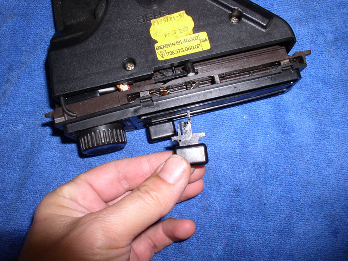
Here's what the new slider ***** look like along side the ****'s sliding spring. The new springs are a different shape than the originals but work just fine. When installing the new slider *****, ensure they are positioned correctly. The top **** should be oriented so the pointer on the face of the **** is pointing downward (as shown) while the bottome slider **** pointer is facing up.
Next, carefully pry and dislodge the top and bottom locking tabs using a small screwdriver so the face place can be removed. However, also.....
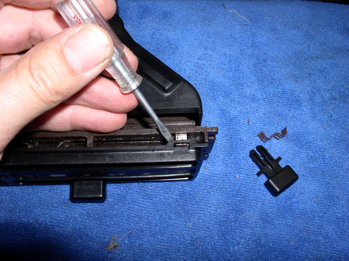
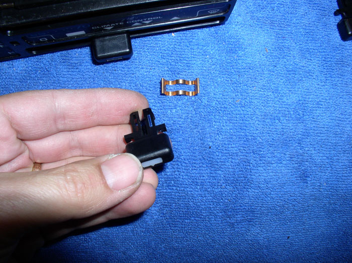
....dislodge the lock tabs on the ends of the face plate as well before removing the face plate.
With the face place moved out of the way, you can remove the old slider spring. Note the optical fiber lighting cable in the center of the spring. This cable provides light for the slider ****.
Install the new slider spring in the same manner as the old spring with the optical fiber going through the center of the slider spring as shown. Perform the same procedure for the other slider **** if it's being repaired as well.
Install the face plate and press it into position ensuring all the lock tabs are properly seated. Then, position the slider **** so the optical fiber cable is inserted into the center hole of the slider ****. You should see plenty of cable showing on the top of the slider **** as shown here. Line up the slider **** prongs with the slider spring and receiving clip on the control unit and press the slider **** into place until it clicks into place. Perform the same operation for both slider *****. I used silicone lubricant to lube the slider spring and track (you could also use white general purpose grease). Test the operation of the slider ***** by moving the sliders to maximum ends of travel. Also note there are detents and button switches at the end of travel on the temperature rail - the slider should easily slide into these detents at the end of travel. If not, you may have an obstruction or the slider **** may not be fully seated.
Next, I re-attached the hose at the air distribution box (behind the glove box).
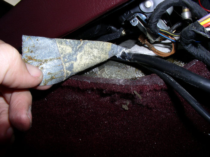
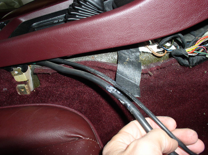
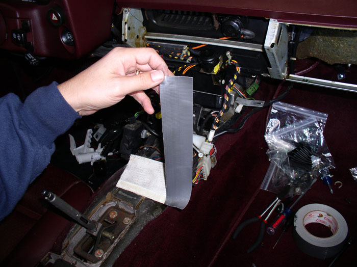
Then I positioned the heat shield fabric (for the cigaratte lighter) back into its original location and cut a strip of duct tape to hold it down. Cut the duct tape with plenty of length as it will also hold down the wiring harness for window switches and rear wiper switch.
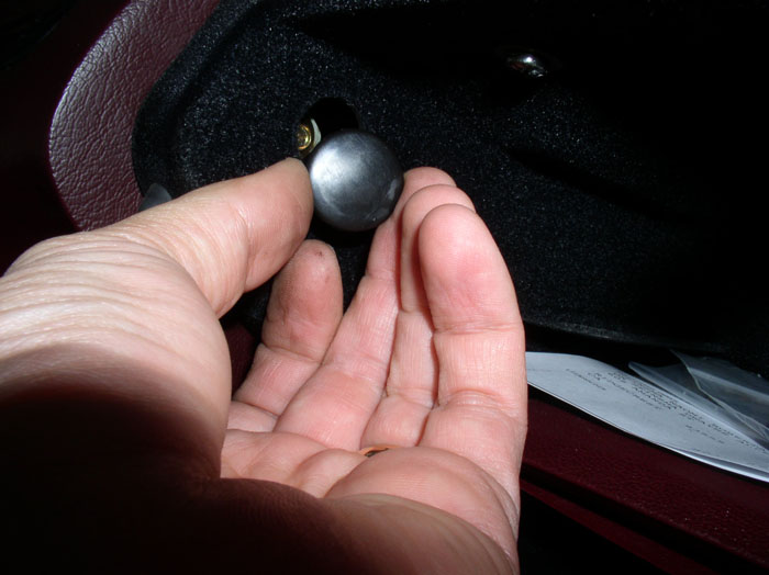
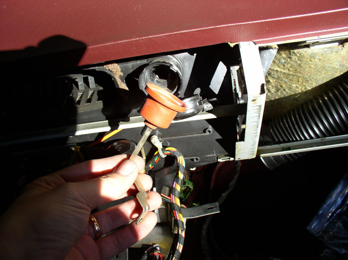
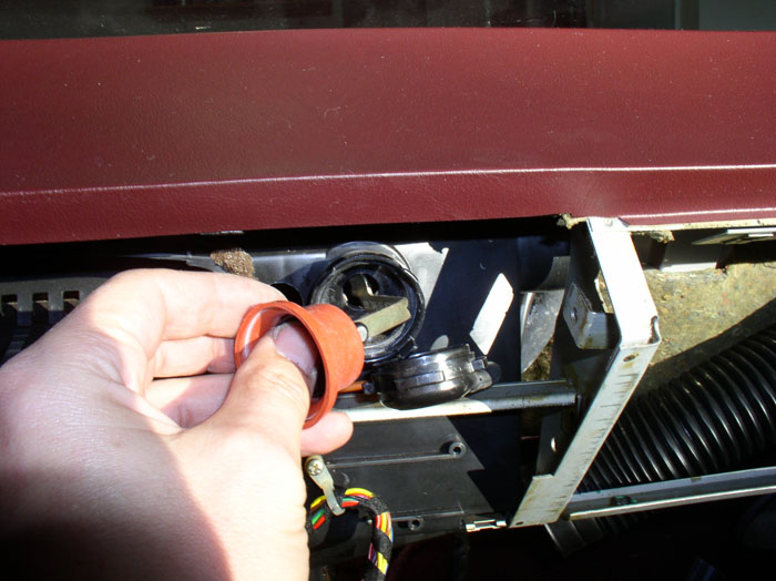
To plug the 3/4" hole I made for the comb flap, I purchased an assortment of body plugs (plastic in this case). Here's the 3/4" size I used to plug the hole.
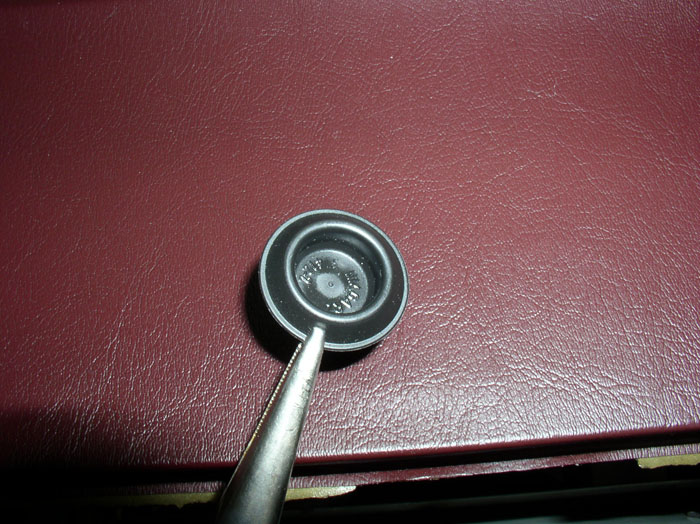
Install the plug in the 3/4" hole.
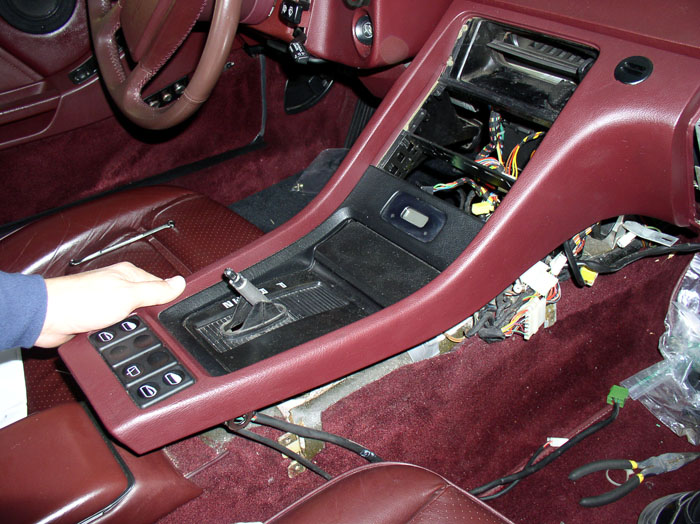
Now you can position the center console. Start by lifting the rear of the console up while positioning the front at the dash.
Then line up the rear of the console with the shift lever and lower the console over the lever as shown.
With the console laying in place, reconnect up the clock wires to the same terminals as they were removed (see below).
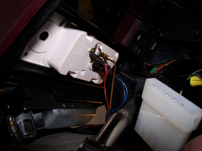
Likewise, attach the wires for the cigarette lighter as shown.
continued......
Here's what the new slider ***** look like along side the ****'s sliding spring. The new springs are a different shape than the originals but work just fine. When installing the new slider *****, ensure they are positioned correctly. The top **** should be oriented so the pointer on the face of the **** is pointing downward (as shown) while the bottome slider **** pointer is facing up.
Next, carefully pry and dislodge the top and bottom locking tabs using a small screwdriver so the face place can be removed. However, also.....
....dislodge the lock tabs on the ends of the face plate as well before removing the face plate.
With the face place moved out of the way, you can remove the old slider spring. Note the optical fiber lighting cable in the center of the spring. This cable provides light for the slider ****.
Install the new slider spring in the same manner as the old spring with the optical fiber going through the center of the slider spring as shown. Perform the same procedure for the other slider **** if it's being repaired as well.
Install the face plate and press it into position ensuring all the lock tabs are properly seated. Then, position the slider **** so the optical fiber cable is inserted into the center hole of the slider ****. You should see plenty of cable showing on the top of the slider **** as shown here. Line up the slider **** prongs with the slider spring and receiving clip on the control unit and press the slider **** into place until it clicks into place. Perform the same operation for both slider *****. I used silicone lubricant to lube the slider spring and track (you could also use white general purpose grease). Test the operation of the slider ***** by moving the sliders to maximum ends of travel. Also note there are detents and button switches at the end of travel on the temperature rail - the slider should easily slide into these detents at the end of travel. If not, you may have an obstruction or the slider **** may not be fully seated.
Next, I re-attached the hose at the air distribution box (behind the glove box).
Then I positioned the heat shield fabric (for the cigaratte lighter) back into its original location and cut a strip of duct tape to hold it down. Cut the duct tape with plenty of length as it will also hold down the wiring harness for window switches and rear wiper switch.
To plug the 3/4" hole I made for the comb flap, I purchased an assortment of body plugs (plastic in this case). Here's the 3/4" size I used to plug the hole.
Install the plug in the 3/4" hole.
Now you can position the center console. Start by lifting the rear of the console up while positioning the front at the dash.
Then line up the rear of the console with the shift lever and lower the console over the lever as shown.
With the console laying in place, reconnect up the clock wires to the same terminals as they were removed (see below).
Likewise, attach the wires for the cigarette lighter as shown.
continued......

