
'87 HVAC Vacuum Leak Testing and Repair Procedure w/pics


 01-02-2011, 09:08 PM
#63
Three Wheelin'
Thread Starter
Join Date: Sep 2007
Location: Ridgecrest, California
Posts: 1,363
Likes: 0
Received 146 Likes
on
30 Posts
Hello all,
Just getting to updating some of my posts and I've updated this HVAC Vacuum Testing and Repair procedure with adding removal and repair of the Recirculation Flap actuator located above the CEB. Previously, this thread only covered repair of the Foot Well and Comb Flap Actuators. I've also updated the the entire writeup to correct the lighting on the dark pictures so they are better quality. I've re-organized the write up to break it into chapters and added a Table of Contents. The updated write up should be on Dwayne's Garage soon. I have not updated this thread with the new pictures or the table of contents. Not sure the best way to do that since it will basically involve reposting the entire thread.. Here we go with the new content....
CH08 REPAIRING AIR RECIRCULATION FLAP DIAPHRAGM
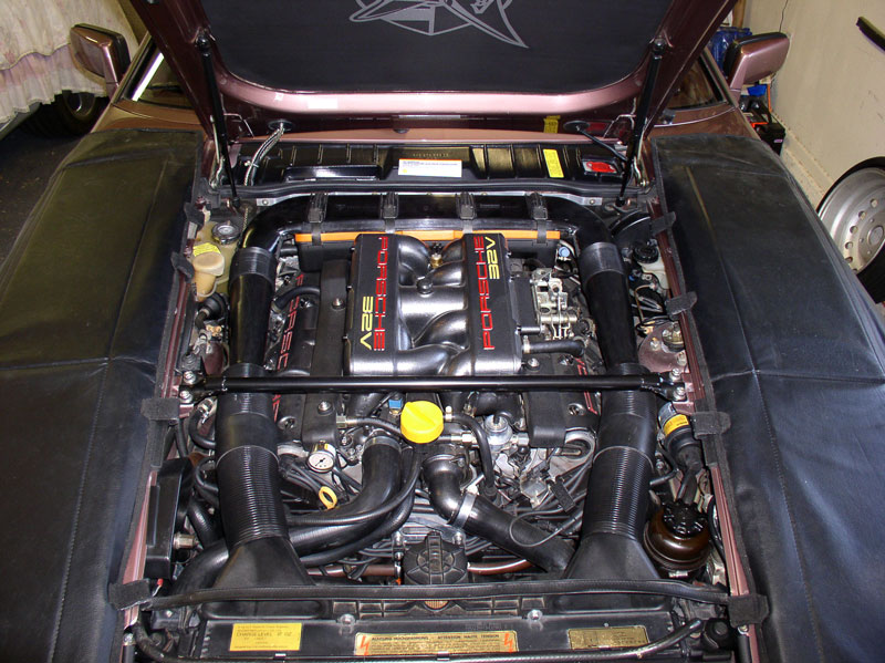
Since I was going to be spending some time working under the hood to get access to various HVAC components, I installed service covers to start the job. In this write up, I took the brute force approach and removed the hood to allow better access to the HVAC blower and recirculation box. I suppose it may be possible to remove the recirculation box without removing the hood or HVAC blower but I have not tried that yet � perhaps on a future repair.
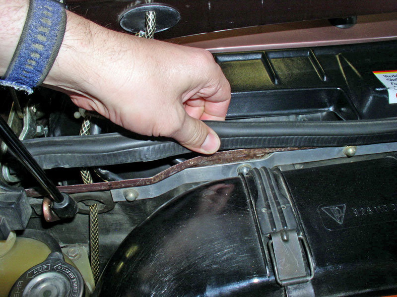
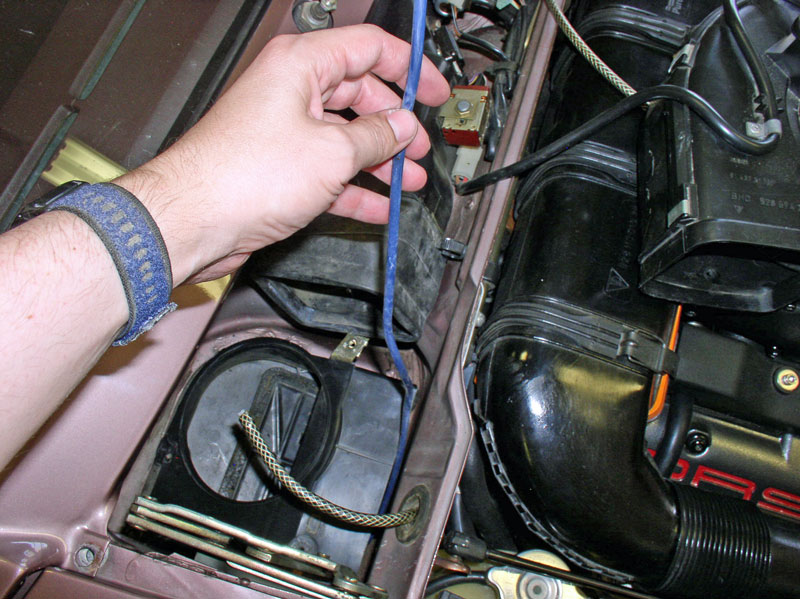
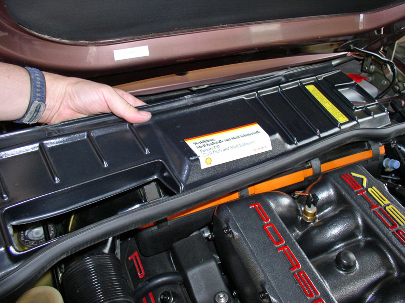
First remove the rain cover at the rear of the engine bay. Pull up on the rubber seal and pull forward disengaging the cover from the three support tabs underneath the windshield wiper valance. Maneuver the cover around the wiring harnesses and washer fluid lines to fully extract the cover.
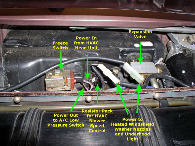
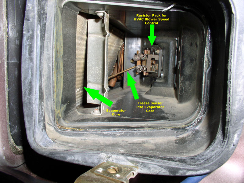
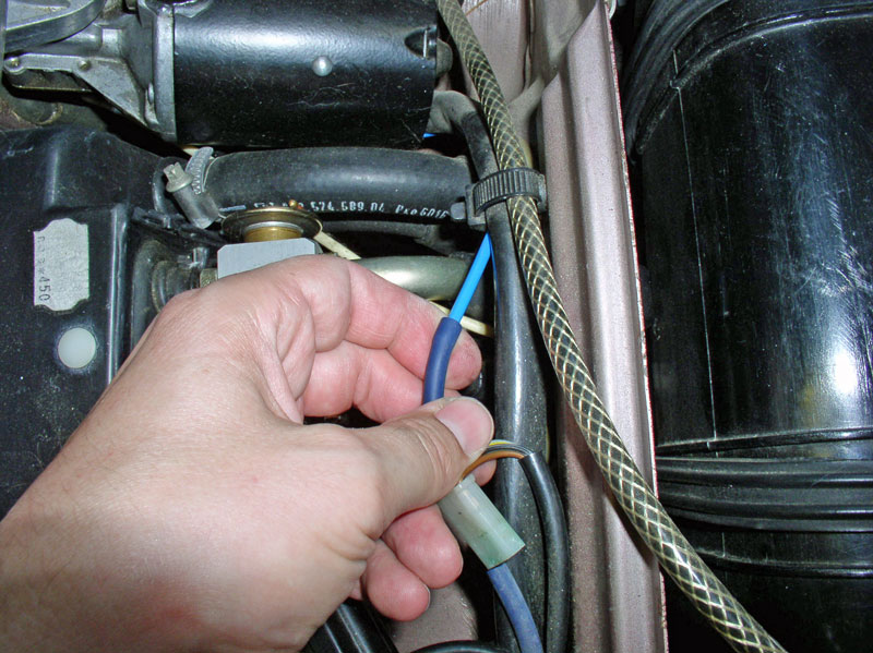
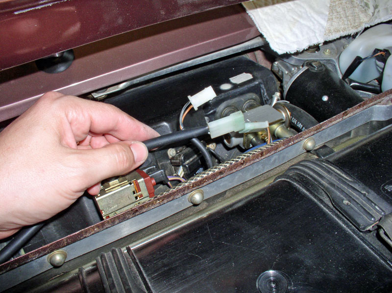
There are several interesting HVAC items under the cover of this 1987 928 worth pointing out along the tour. The Expansion Valve allows the liquid refrigerant coming from the condenser at the front of the engine to move from a high pressure zone to a low pressure zone and in the process the liquid turns into a gas and evaporates absorbing heat in the process and producing very cold temperatures in the evaporator core. If there is moisture in the air around the evaporator, the moisture can condense on the evaporator fins and freeze. The Freeze Switch monitors the outside temperature of the evaporator core via a probe that is inserted into the evaporator core. On warm, humid days when the A/C is run for long periods, water can condense on the evaporator fins and eventually freeze up into a block of ice preventing air flow through the evaporator. The freeze switch has a 2-wire power lead coming into it and a single wire carrying power outbound from the switch. Power is coming into the switch from the HVAC head unit in the dash. The outbound power goes to the CEB and splits off in two directions. One line goes to the Suppressor relay (XI) on the CEB board and the other line goes out the CEB to the A/C refrigerant low pressure switch located in front of the condenser. As long as the external temperature of the evaporator core is above freezing, the circuit in the freeze switch is closed and allows current to pass on to the low pressure switch. If the temperature from the probe is below freezing, the circuit is opened and power is cut which results in no power going to the A/C compressor clutch and effectively shuts down the refrigerant cycle. This helps prevent the evaporator core from turning into a block of ice. You will also see the harness plug for the Resistor Pack for the HVAC Blower Speed Control. The Resistor Pack applies different levels of resistance to the current supplied to the HVAC Blower motor to control speed. Finally, there are two harness plugs of interest. These will have to be disconnected in order to remove the hood. There is a 2-wire connector leading to the left (driver side) of the hood. These wires power the heated windshield spray nozzle in the hood. The other 3-wire connector powers the heated nozzle for the right side of the hood and contains an additional wire for the under hood light.
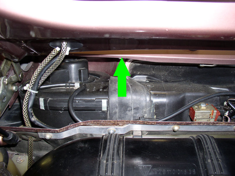
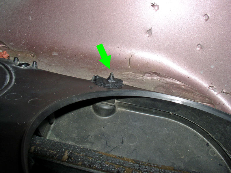
You will notice there is not much clearance to remove the blower motor. The wiper arm valance is the main obstacle indicated by the green arrow and the hood also prevents easy removal of the motor. However, I understand it is possible to remove the motor without removing the hood by simply disconnecting the hood from the hinge bracket to the left of the motor allowing the hood to be �lifted up� enough to get the clearance needed to remove the motor. However, that�s not what I did in this write up.
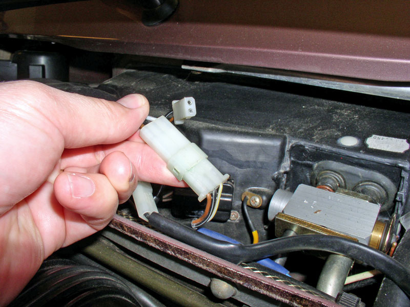
To remove the hood, first disconnect the 2 and 3 wire connectors leading to the underside of the hood for nozzles and hood light.
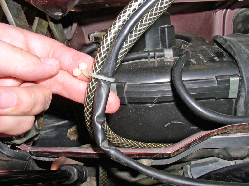
Remove the harness tie for the heated nozzle wiring harness.
Disconnect the harness tie to the left of the freeze switch.
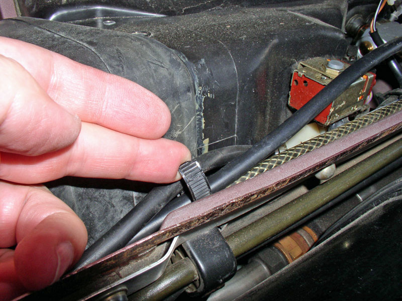
Remove the harness and washer supply hose tie near the blower motor.
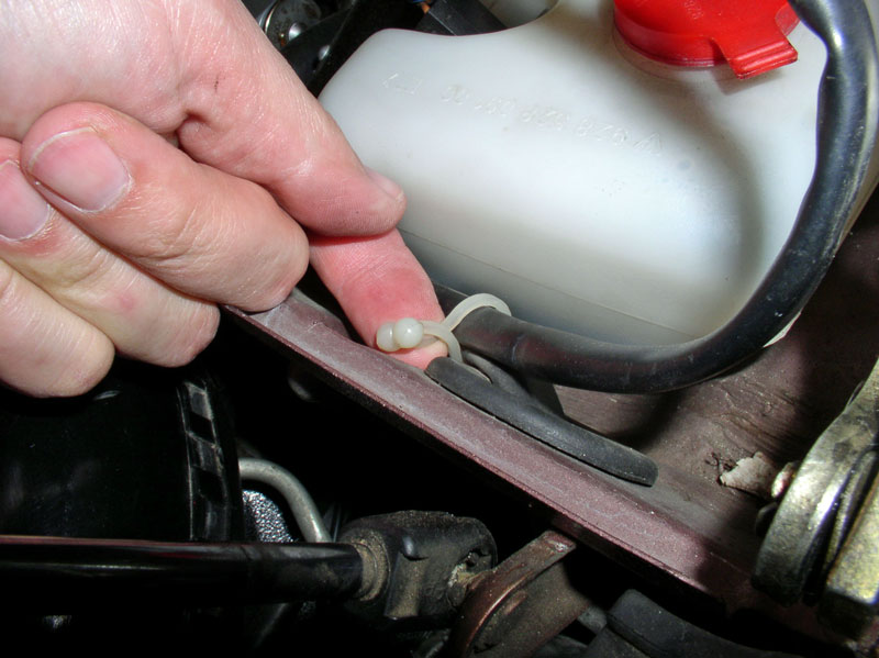
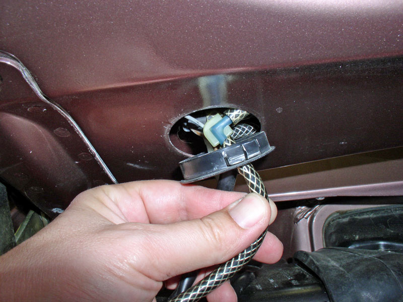
You will need to disconnect the windshield washer fluid lines from the hood connector. There are two lines � a supply line and a return line.
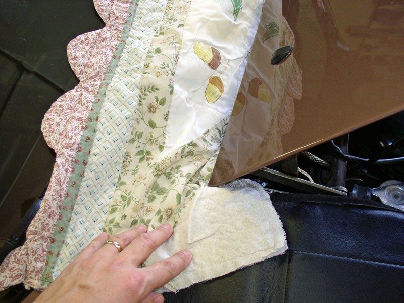
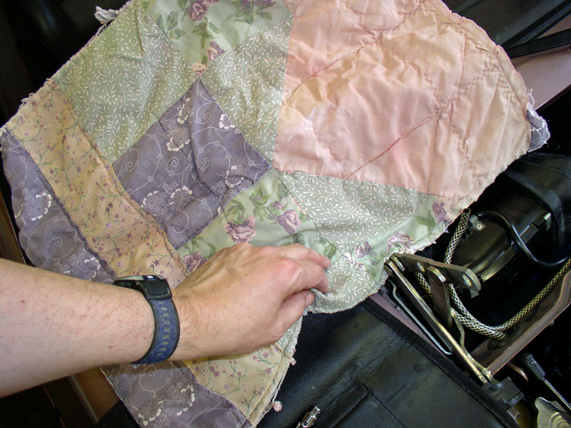
I placed a segment of old quilted comforter between both corners of the hood and fenders to prevent damage to both surfaces during hood removal.
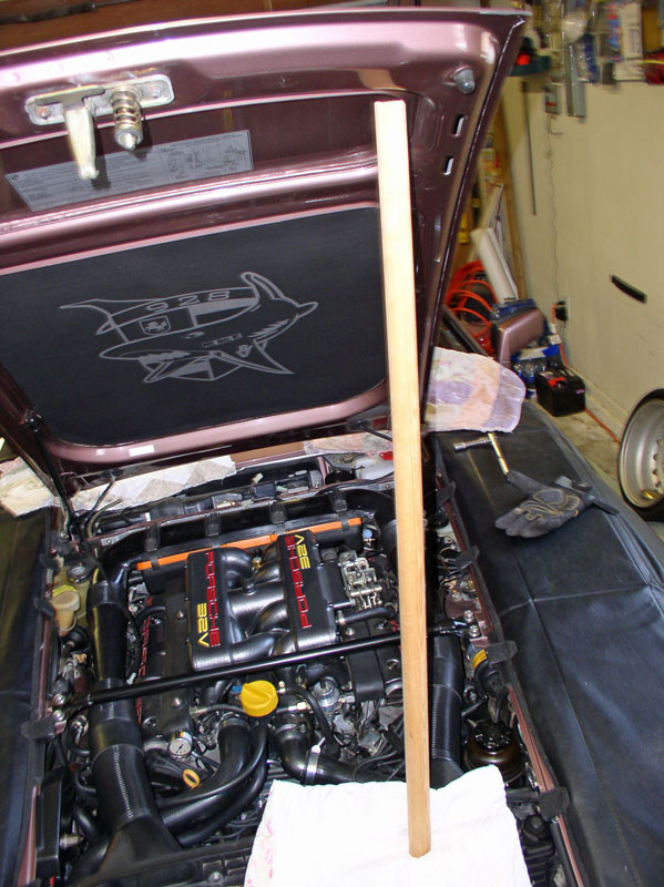
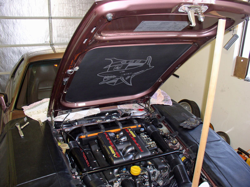
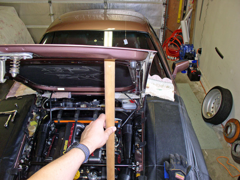
Support the hood before removing the hood shocks. I used a segment of a closet dowel to support the hood during the removal process as shown here.
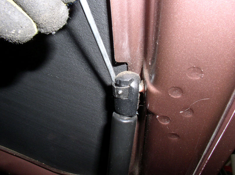
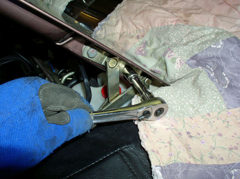
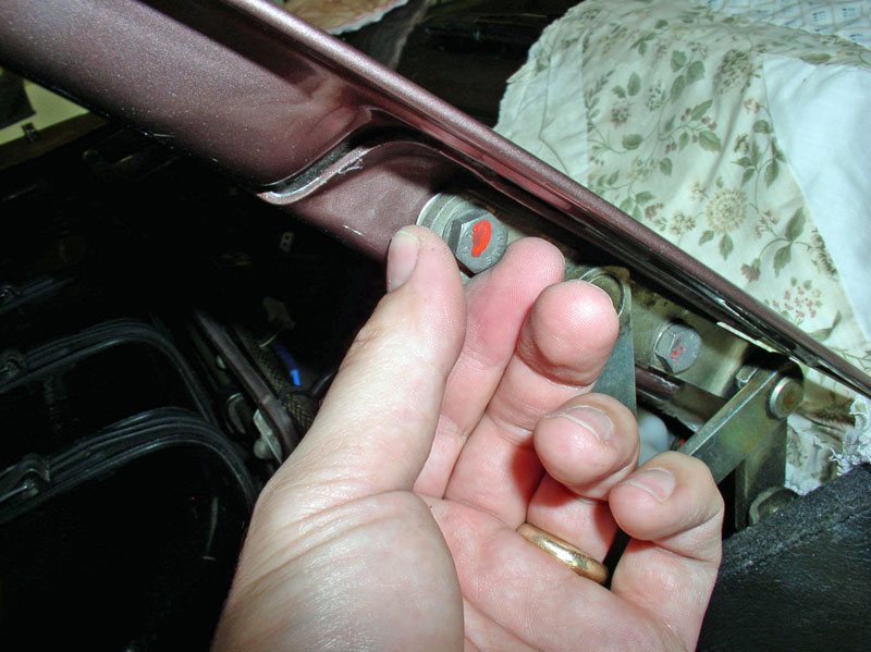
Remove the hood shocks at the hood and allow it to swing down into the engine bay. The shock is removed by prying the locking retaining clip out as pictured below and pull the shock mount away from the ball connector on the hood.
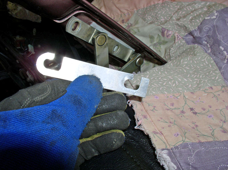
Before removing the hinge bolts, you may want to mark the location of the hinge on the hood for easier re-installation. You can use a permanent marker or painter�s tape. Remove the two 13mm bolts that secure the hood to the hinge.
You may have shims between the hinge and hood. If so, note their orientation and keep the shims associated with their respective hinge (left or right). Repeat for the other side.
The hood should now be fully supported by the closet dowel and resting on the quilted comforters as depicted below. The hood is light and can be lifted and maneuvered to a resting place by one person but if you have a helper, an extra hand may come in handy. I held up the hood with one hand and removed the dowel with the other. I then grasped the hood with one hand on each side and lifted it away from the car.
Continued....
Just getting to updating some of my posts and I've updated this HVAC Vacuum Testing and Repair procedure with adding removal and repair of the Recirculation Flap actuator located above the CEB. Previously, this thread only covered repair of the Foot Well and Comb Flap Actuators. I've also updated the the entire writeup to correct the lighting on the dark pictures so they are better quality. I've re-organized the write up to break it into chapters and added a Table of Contents. The updated write up should be on Dwayne's Garage soon. I have not updated this thread with the new pictures or the table of contents. Not sure the best way to do that since it will basically involve reposting the entire thread.. Here we go with the new content....
CH08 REPAIRING AIR RECIRCULATION FLAP DIAPHRAGM
Since I was going to be spending some time working under the hood to get access to various HVAC components, I installed service covers to start the job. In this write up, I took the brute force approach and removed the hood to allow better access to the HVAC blower and recirculation box. I suppose it may be possible to remove the recirculation box without removing the hood or HVAC blower but I have not tried that yet � perhaps on a future repair.
First remove the rain cover at the rear of the engine bay. Pull up on the rubber seal and pull forward disengaging the cover from the three support tabs underneath the windshield wiper valance. Maneuver the cover around the wiring harnesses and washer fluid lines to fully extract the cover.
There are several interesting HVAC items under the cover of this 1987 928 worth pointing out along the tour. The Expansion Valve allows the liquid refrigerant coming from the condenser at the front of the engine to move from a high pressure zone to a low pressure zone and in the process the liquid turns into a gas and evaporates absorbing heat in the process and producing very cold temperatures in the evaporator core. If there is moisture in the air around the evaporator, the moisture can condense on the evaporator fins and freeze. The Freeze Switch monitors the outside temperature of the evaporator core via a probe that is inserted into the evaporator core. On warm, humid days when the A/C is run for long periods, water can condense on the evaporator fins and eventually freeze up into a block of ice preventing air flow through the evaporator. The freeze switch has a 2-wire power lead coming into it and a single wire carrying power outbound from the switch. Power is coming into the switch from the HVAC head unit in the dash. The outbound power goes to the CEB and splits off in two directions. One line goes to the Suppressor relay (XI) on the CEB board and the other line goes out the CEB to the A/C refrigerant low pressure switch located in front of the condenser. As long as the external temperature of the evaporator core is above freezing, the circuit in the freeze switch is closed and allows current to pass on to the low pressure switch. If the temperature from the probe is below freezing, the circuit is opened and power is cut which results in no power going to the A/C compressor clutch and effectively shuts down the refrigerant cycle. This helps prevent the evaporator core from turning into a block of ice. You will also see the harness plug for the Resistor Pack for the HVAC Blower Speed Control. The Resistor Pack applies different levels of resistance to the current supplied to the HVAC Blower motor to control speed. Finally, there are two harness plugs of interest. These will have to be disconnected in order to remove the hood. There is a 2-wire connector leading to the left (driver side) of the hood. These wires power the heated windshield spray nozzle in the hood. The other 3-wire connector powers the heated nozzle for the right side of the hood and contains an additional wire for the under hood light.
You will notice there is not much clearance to remove the blower motor. The wiper arm valance is the main obstacle indicated by the green arrow and the hood also prevents easy removal of the motor. However, I understand it is possible to remove the motor without removing the hood by simply disconnecting the hood from the hinge bracket to the left of the motor allowing the hood to be �lifted up� enough to get the clearance needed to remove the motor. However, that�s not what I did in this write up.
To remove the hood, first disconnect the 2 and 3 wire connectors leading to the underside of the hood for nozzles and hood light.
Remove the harness tie for the heated nozzle wiring harness.
Disconnect the harness tie to the left of the freeze switch.
Remove the harness and washer supply hose tie near the blower motor.
You will need to disconnect the windshield washer fluid lines from the hood connector. There are two lines � a supply line and a return line.
I placed a segment of old quilted comforter between both corners of the hood and fenders to prevent damage to both surfaces during hood removal.
Support the hood before removing the hood shocks. I used a segment of a closet dowel to support the hood during the removal process as shown here.
Remove the hood shocks at the hood and allow it to swing down into the engine bay. The shock is removed by prying the locking retaining clip out as pictured below and pull the shock mount away from the ball connector on the hood.
Before removing the hinge bolts, you may want to mark the location of the hinge on the hood for easier re-installation. You can use a permanent marker or painter�s tape. Remove the two 13mm bolts that secure the hood to the hinge.
You may have shims between the hinge and hood. If so, note their orientation and keep the shims associated with their respective hinge (left or right). Repeat for the other side.
The hood should now be fully supported by the closet dowel and resting on the quilted comforters as depicted below. The hood is light and can be lifted and maneuvered to a resting place by one person but if you have a helper, an extra hand may come in handy. I held up the hood with one hand and removed the dowel with the other. I then grasped the hood with one hand on each side and lifted it away from the car.
Continued....
01-02-2011, 09:19 PM
#64
Three Wheelin'
Thread Starter
Join Date: Sep 2007
Location: Ridgecrest, California
Posts: 1,363
Likes: 0
Received 146 Likes
on
30 Posts
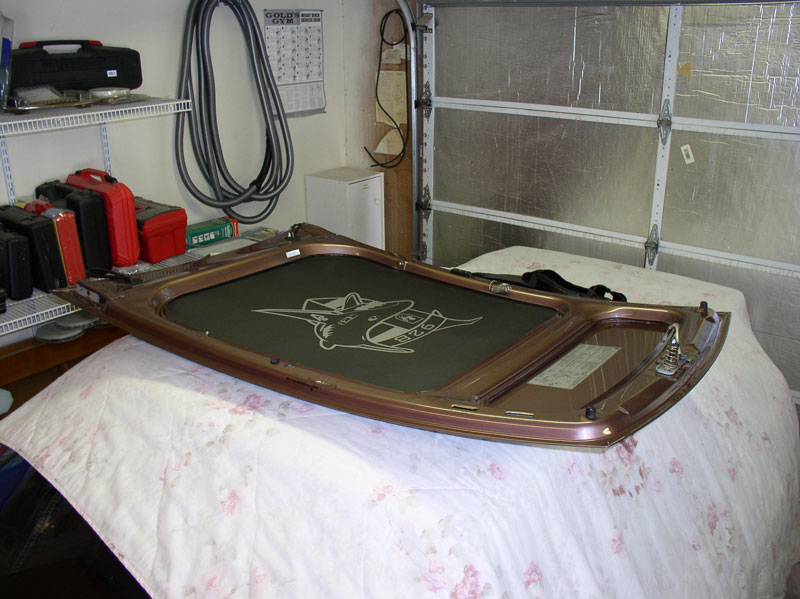
You can store the hood on a soft location such as below. If you stand it up somewhere, be sure and place some protective cloth or cardboard underneath it.
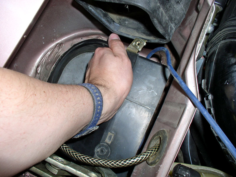
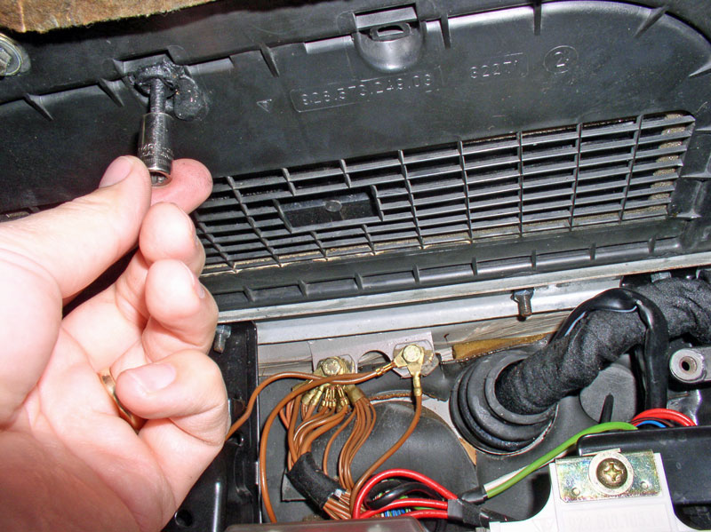
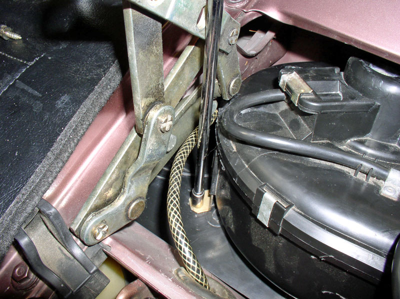
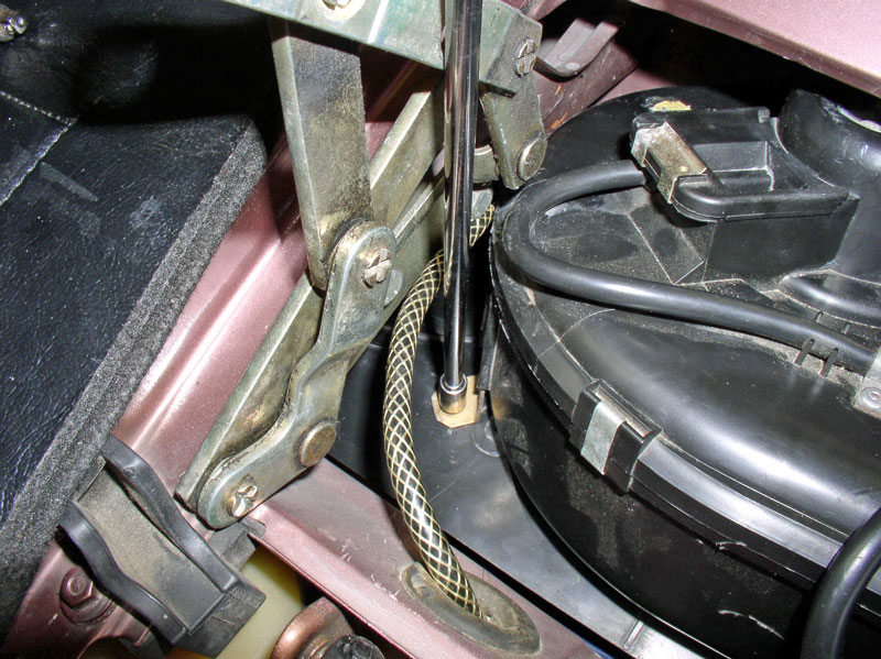
Next, I proceeded to remove the HVAC blower. First, I removed the easy 8mm screw on the front side as seen below.
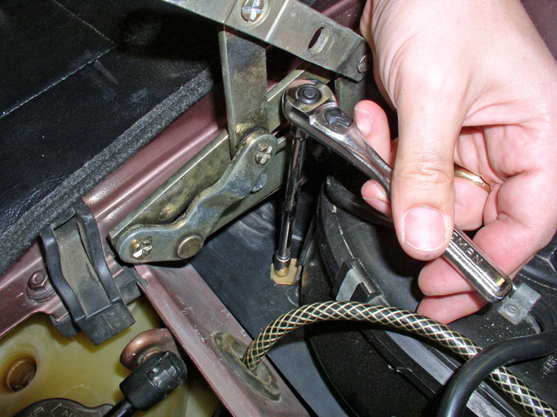
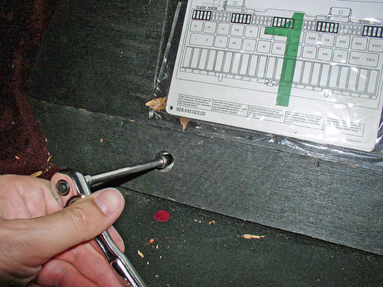
The not-so-easy screw is located at the air exit end of the blower under the rubber gasket-coupler between the blower and air box. It is an 8mm screw and I used an elbow and extension bar to get at it. You will need to hold back the rubber coupler during the operation.

This procedure assumes you have left off the storage tray from removing the center console previously. If you have not done so already, you will need to remove the storage tray on the passenger foot well next. The third screw securing the blower is underneath the glove box and goes through the air recirculation box as seen below. It is an 8mm screw and considerably longer than the other two.
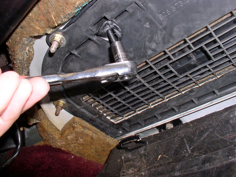
As you remove this screw, you may notice non-hardening sealant on the screw threads as it comes out � mine did. Apparently, this screw had non-hardening sealant around it to prevent leakage.
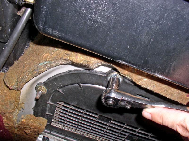
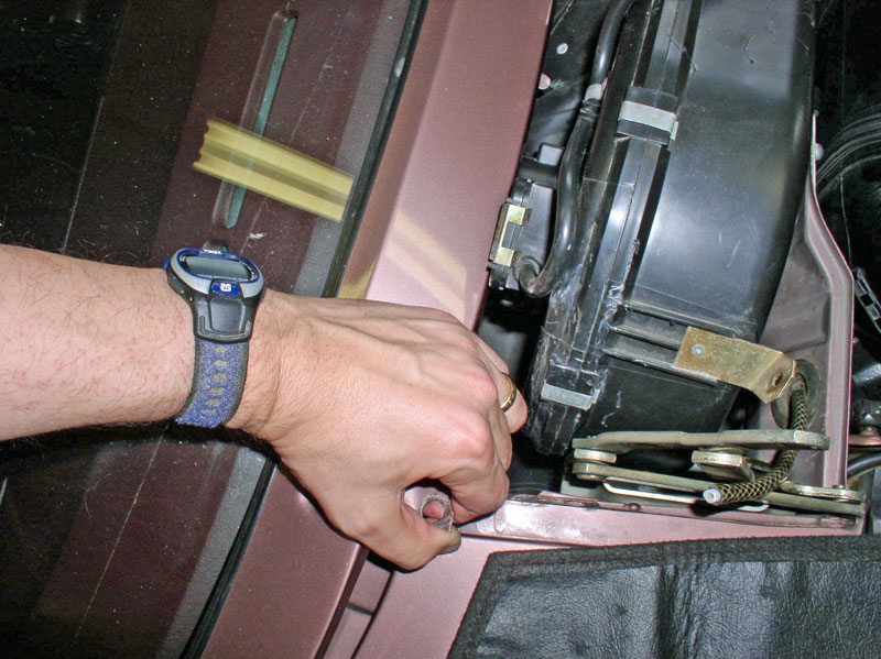
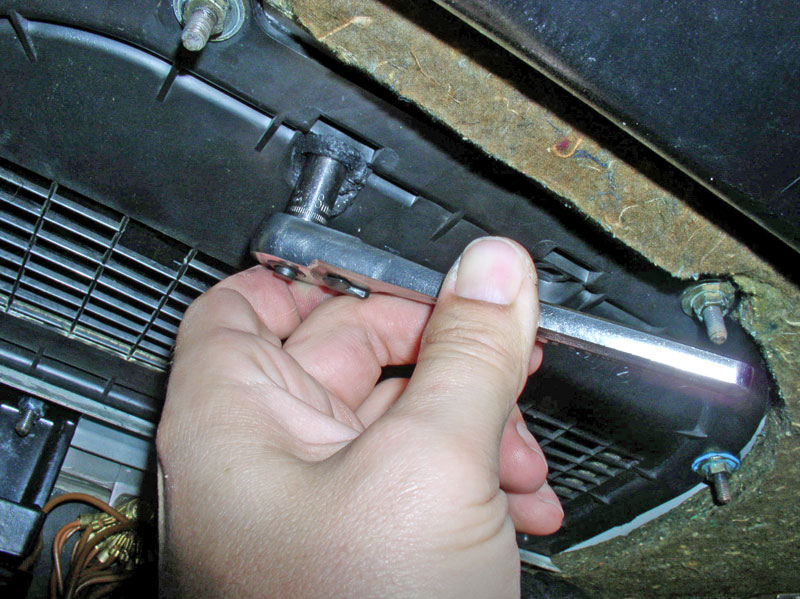
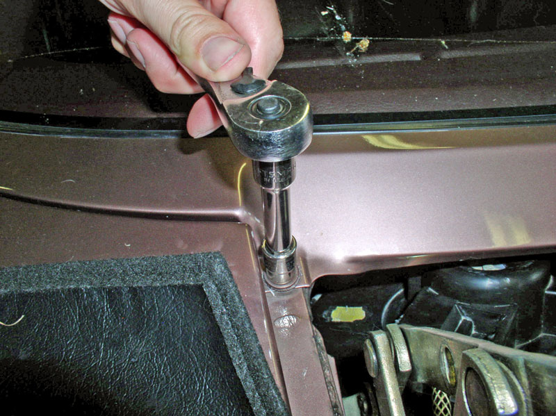
Back above, I needed to loosen the wiper arm valance enough to give clearance to remove the blower motor. Begin by removing the 10mm bolt that secures the valance to the fender as shown below.
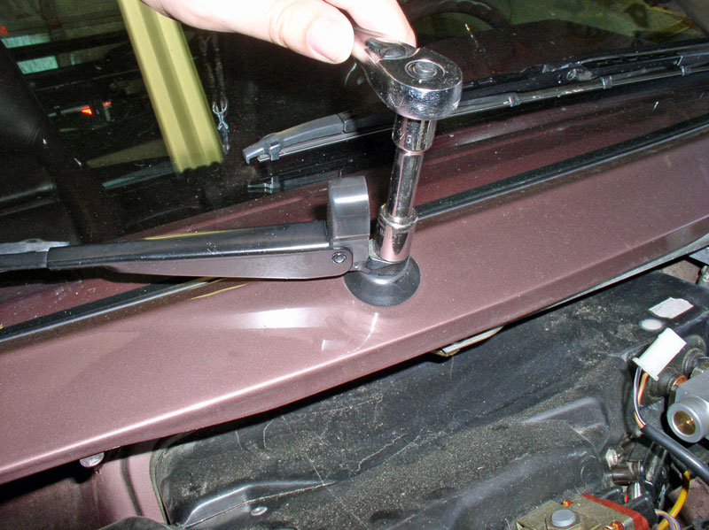
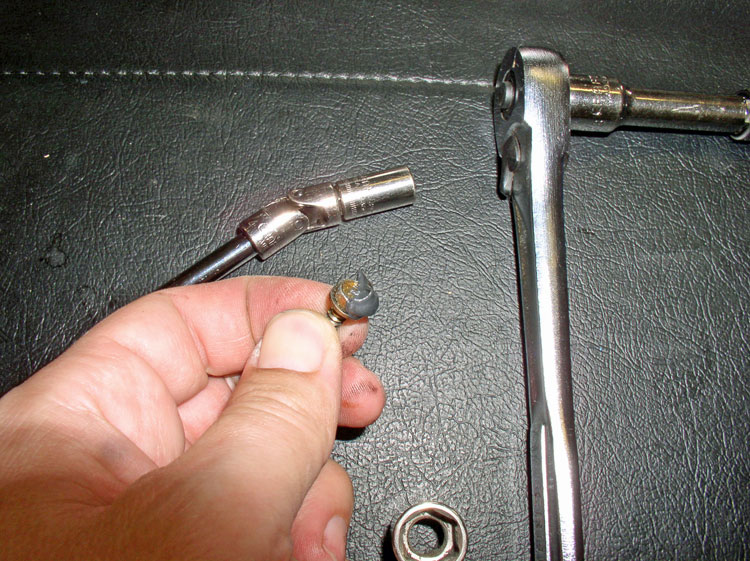
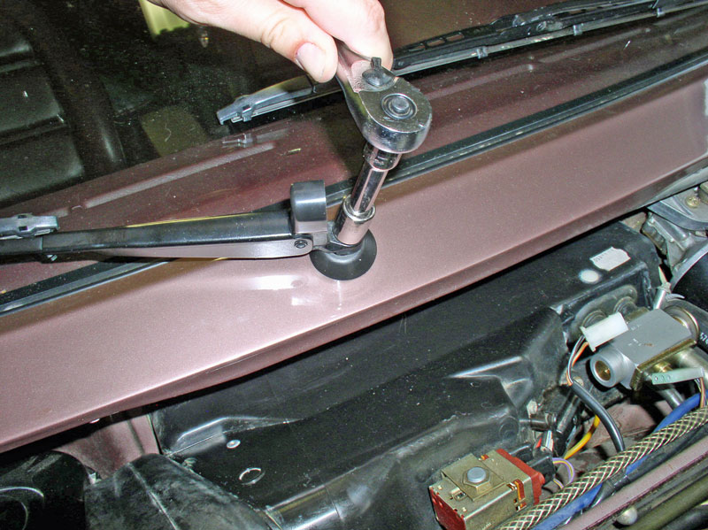
I removed the wiper arms to allow the valance to move upward. Use a 13mm socket or wrench to remove the retaining nut then pull up on the wiper arm to disengage it from the spindle.
At this point, I was able to carefully pull up on the wiper valance while maneuvering the blower motor out � no problem.
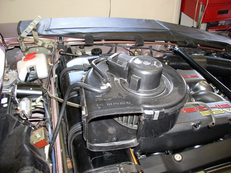
Once the motor is out, you can set it aside without having to disconnect the power harness. The motor casing can be removed and the motor serviced but that is not covered here since I wasn�t having any trouble with the motor.
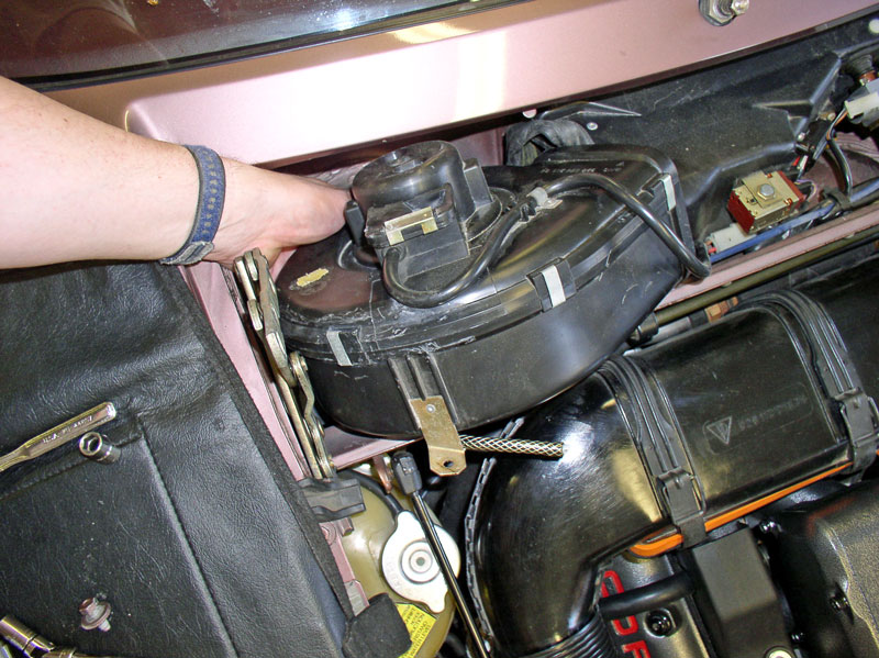
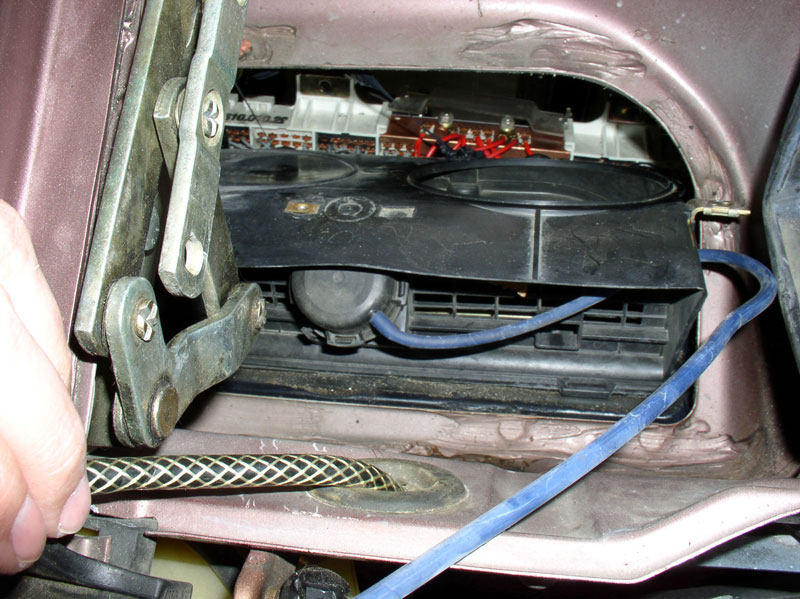
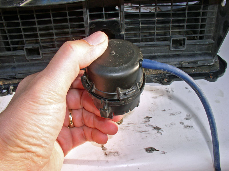
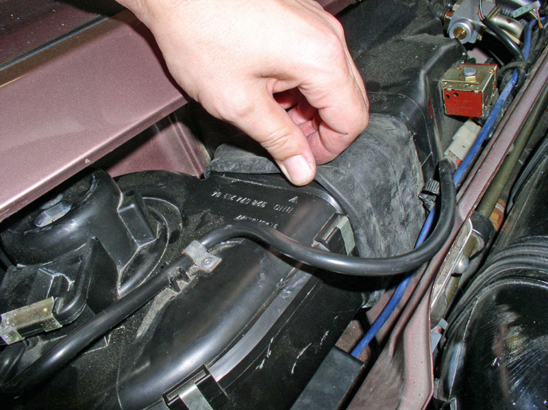
You can now see the topside of the air recirculation box. There is a blue vacuum line coming into the box that connects to the vacuum actuator � our main objective!
If you look into the air box, you will see a few interesting items. Straight ahead is the Resistor Pack for HVAC Blower Speed Control. Next to that you can see the Freeze Switch probe that leads to the evaporator core. And you can see the evaporator core itself � the front side of it anyway. It�s a good idea to inspect the evaporator core for obstructions to air flow like leaves, feathers, dust/dirt accumulation. You can use a stiff nylon brush to carefully brush and clean between the evaporator fins and vacuum out any loose debris.
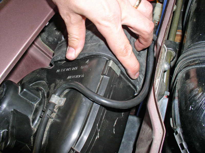
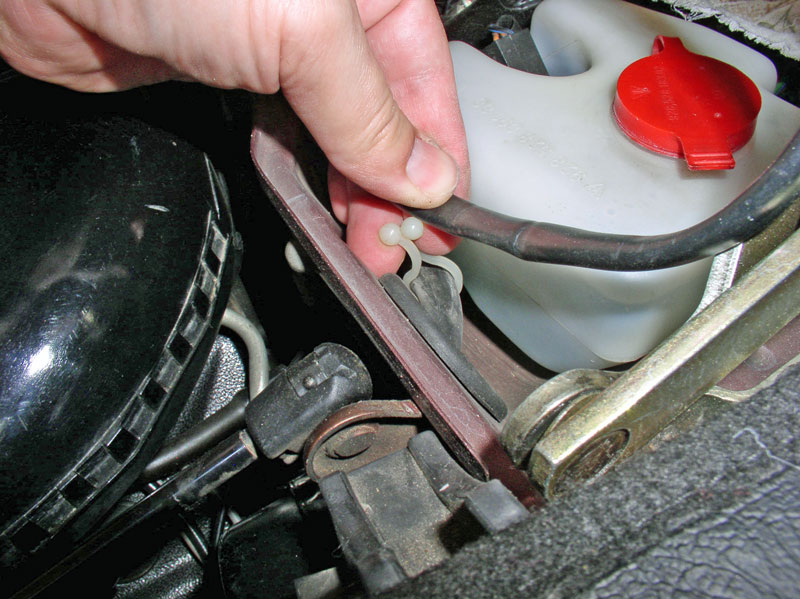
Next, locate the flexible silicone blue vacuum line and disconnect it where it meets the blue hard plastic line near the wiper motor.
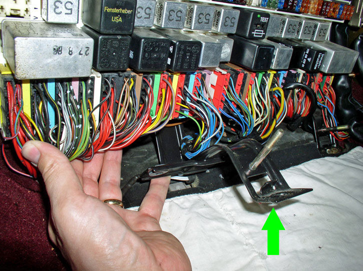
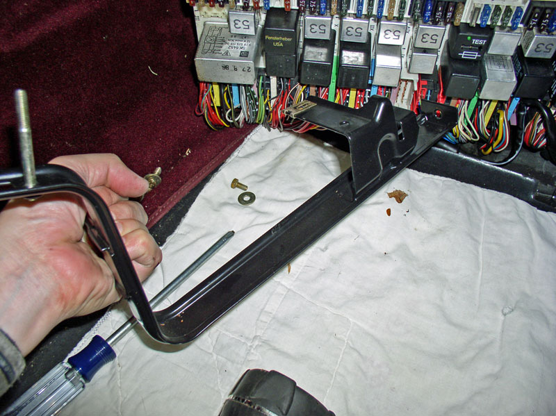
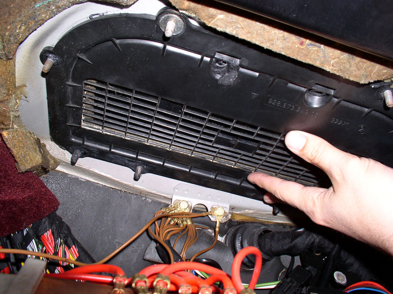
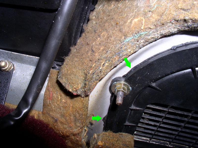
Down below, we need to get things ready to remove the recirculation box. I first removed the two 10mm nuts that secure the lower half of the foot rest.
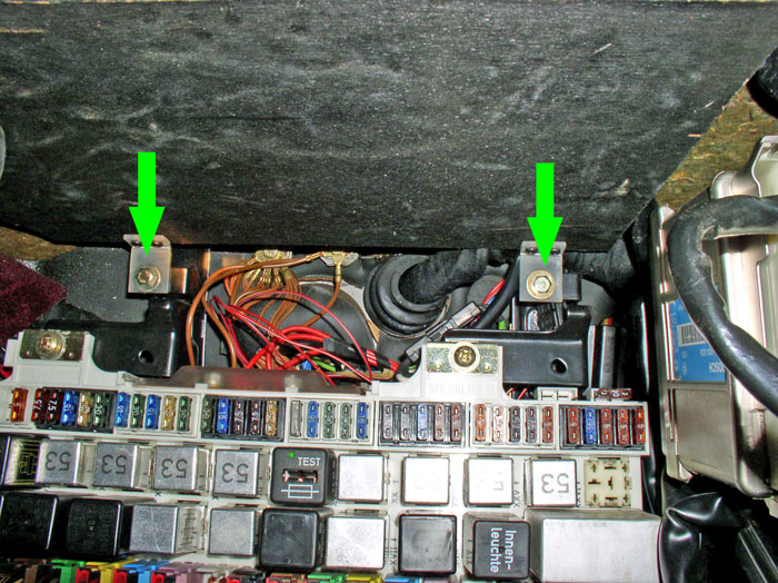
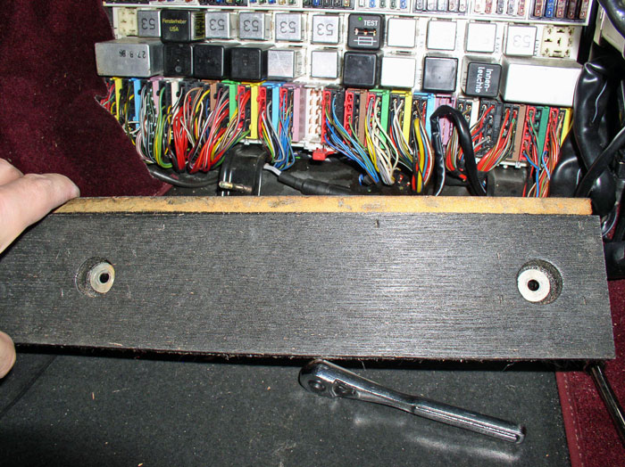
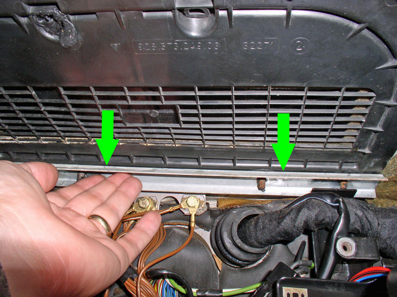
Then, remove the two 10mm bolts that secure the upper half of the foot rest/CEB door to the support brackets as indicated by the green arrows below.
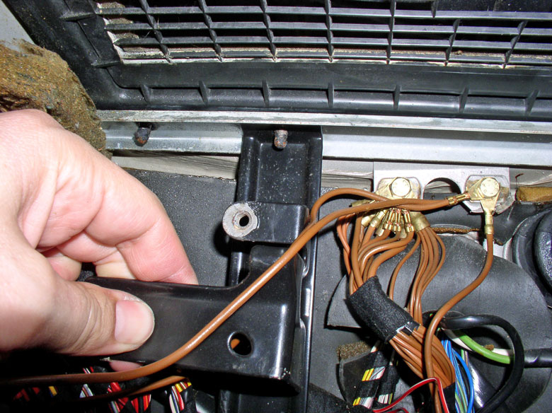
Remove the lower half of the foot rest.
Continued....
Next, I proceeded to remove the HVAC blower. First, I removed the easy 8mm screw on the front side as seen below.
The not-so-easy screw is located at the air exit end of the blower under the rubber gasket-coupler between the blower and air box. It is an 8mm screw and I used an elbow and extension bar to get at it. You will need to hold back the rubber coupler during the operation.
This procedure assumes you have left off the storage tray from removing the center console previously. If you have not done so already, you will need to remove the storage tray on the passenger foot well next. The third screw securing the blower is underneath the glove box and goes through the air recirculation box as seen below. It is an 8mm screw and considerably longer than the other two.
As you remove this screw, you may notice non-hardening sealant on the screw threads as it comes out � mine did. Apparently, this screw had non-hardening sealant around it to prevent leakage.
Back above, I needed to loosen the wiper arm valance enough to give clearance to remove the blower motor. Begin by removing the 10mm bolt that secures the valance to the fender as shown below.
I removed the wiper arms to allow the valance to move upward. Use a 13mm socket or wrench to remove the retaining nut then pull up on the wiper arm to disengage it from the spindle.
At this point, I was able to carefully pull up on the wiper valance while maneuvering the blower motor out � no problem.
Once the motor is out, you can set it aside without having to disconnect the power harness. The motor casing can be removed and the motor serviced but that is not covered here since I wasn�t having any trouble with the motor.
You can now see the topside of the air recirculation box. There is a blue vacuum line coming into the box that connects to the vacuum actuator � our main objective!
If you look into the air box, you will see a few interesting items. Straight ahead is the Resistor Pack for HVAC Blower Speed Control. Next to that you can see the Freeze Switch probe that leads to the evaporator core. And you can see the evaporator core itself � the front side of it anyway. It�s a good idea to inspect the evaporator core for obstructions to air flow like leaves, feathers, dust/dirt accumulation. You can use a stiff nylon brush to carefully brush and clean between the evaporator fins and vacuum out any loose debris.
Next, locate the flexible silicone blue vacuum line and disconnect it where it meets the blue hard plastic line near the wiper motor.
Down below, we need to get things ready to remove the recirculation box. I first removed the two 10mm nuts that secure the lower half of the foot rest.
Then, remove the two 10mm bolts that secure the upper half of the foot rest/CEB door to the support brackets as indicated by the green arrows below.
Remove the lower half of the foot rest.
Continued....
01-02-2011, 09:27 PM
#65
Three Wheelin'
Thread Starter
Join Date: Sep 2007
Location: Ridgecrest, California
Posts: 1,363
Likes: 0
Received 146 Likes
on
30 Posts
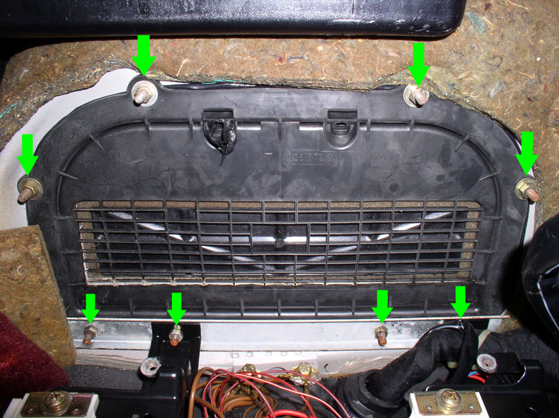
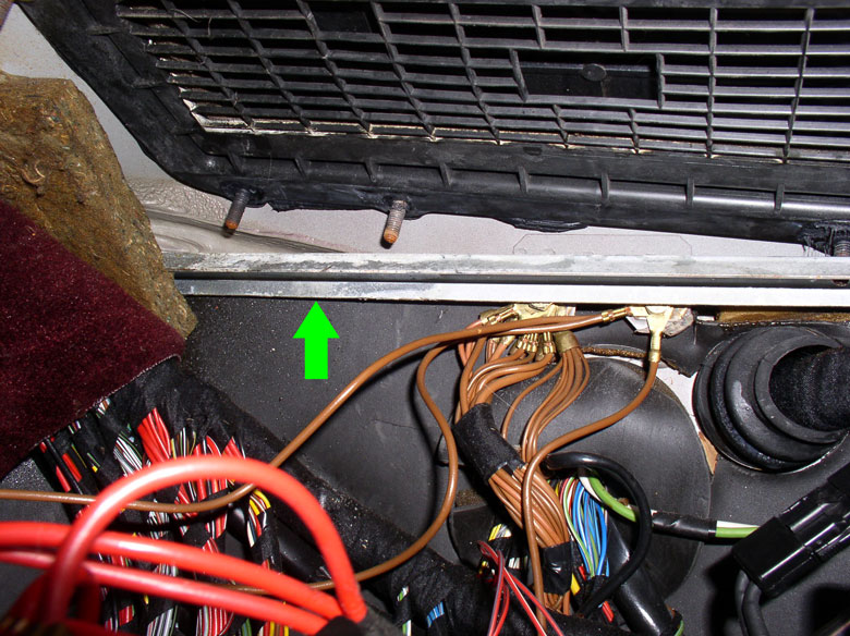
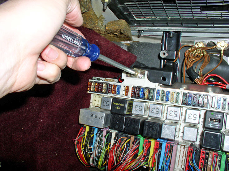
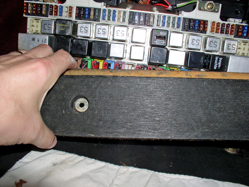
The recirculation box is secured to the body by eight 10mm nuts as identified by the arrows in the pic below. The 4 nuts at the bottom of the pic have added CEB support brackets that will need to be moved as well.
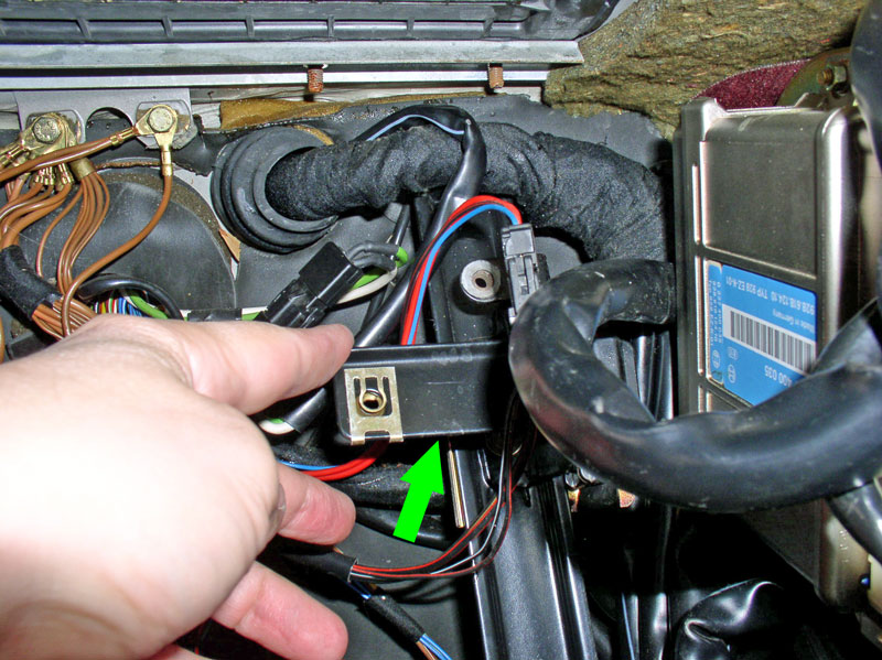
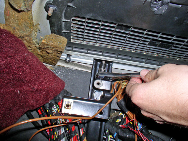
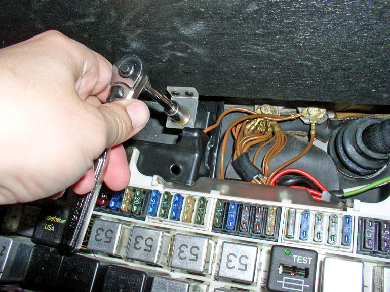
We will need to remove the two CEB support brackets and lower them out of the way. I started by removing the upper nut on both brackets.
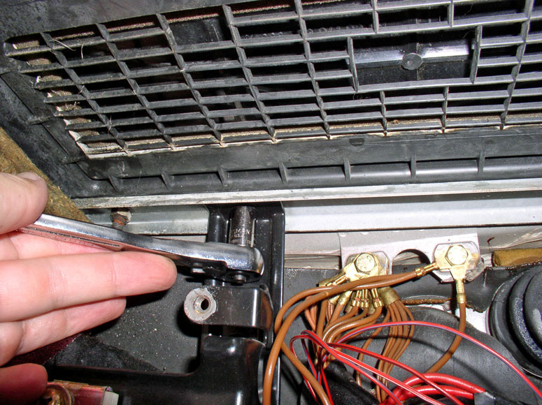
I don�t believe it is required to disconnect the CEB from it�s support brackets in order to remove the recirculation box. However, I wanted maximum maneuverability when removing the recirculation box so decided to disconnect the CEB from it�s support brackets which is as simple as removing a couple of screws. I removed the left and right Phillips screws as shown below.
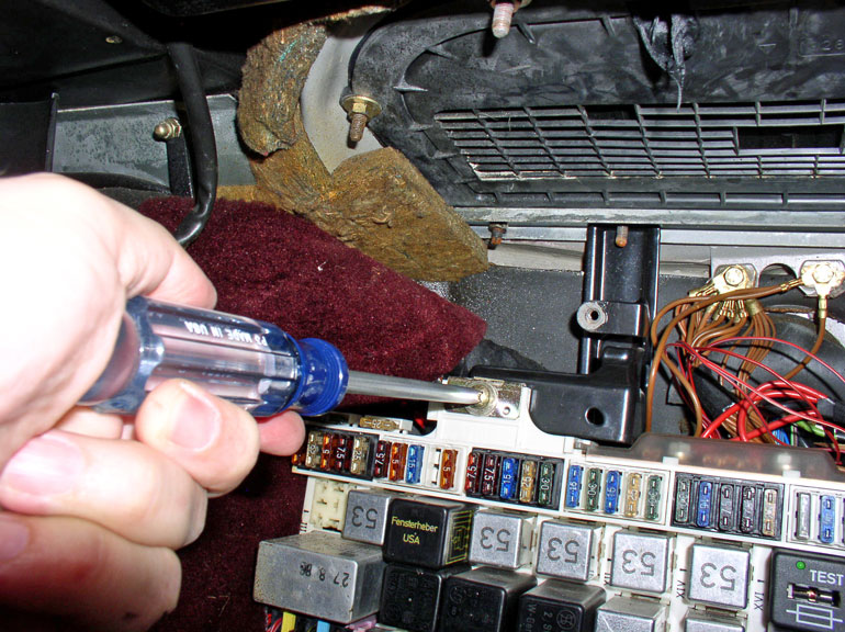
You will also need to remove the 10mm bolt securing the support bracket to the floor board. Remove the bolt for the other bracket as well.

At this point, I could easily lift up on the bracket and pull it forward as shown below.
Although not necessary, I found the left bracket easy enough to remove altogether.
The right bracket isn�t so easy to fully remove so I left it in place but lifted it up and out in the same manner as the right bracket and only moved it down enough to be out of the way as pictured below.
Remove the remaining two 10mm nuts on the forward edge of the recirculation box and the metal support bar can be removed � see below.
Remove the remaining four 10mm nuts around the sides and rearward edge of the recirculation box.
The only thing securing the recirculation box to the body at this point is the sealant to prevent water leakage. I pressed down on the box from above with only enough force to break the seal and free the box.
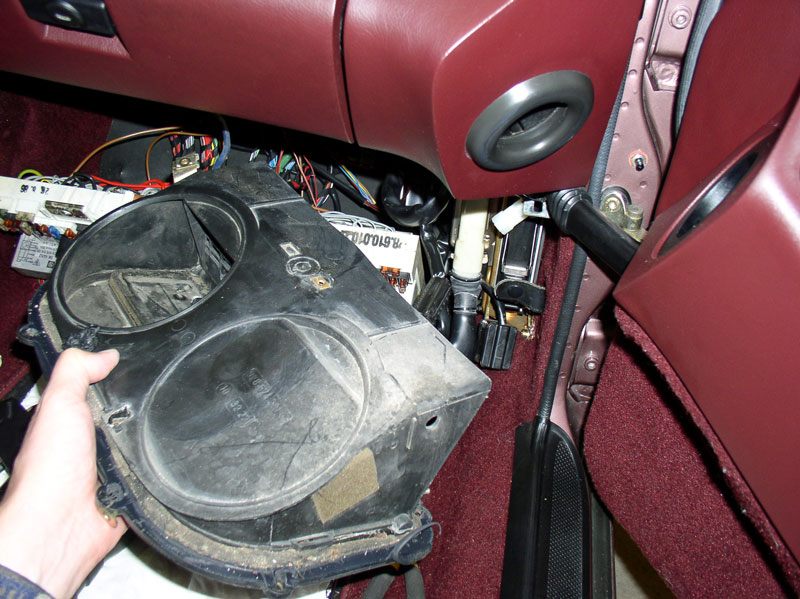
Maneuver the box down into the foot well from above.
From underneath the glove box, continue maneuvering the box out.
And remove it from the car.
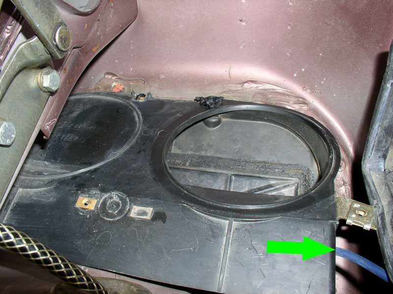
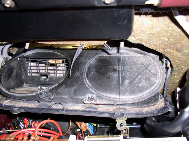
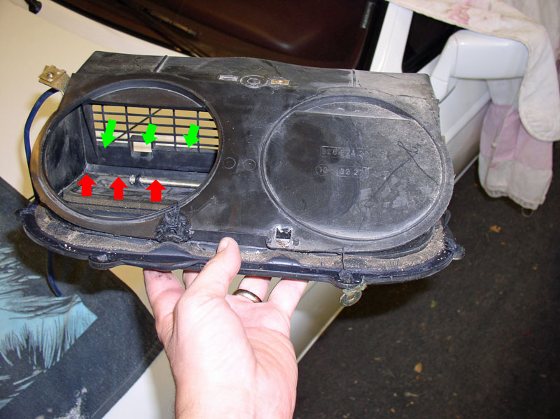
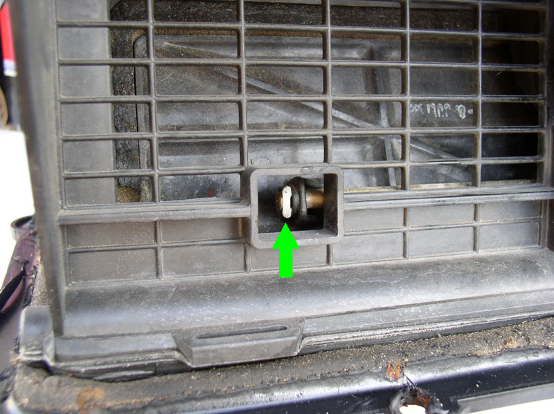
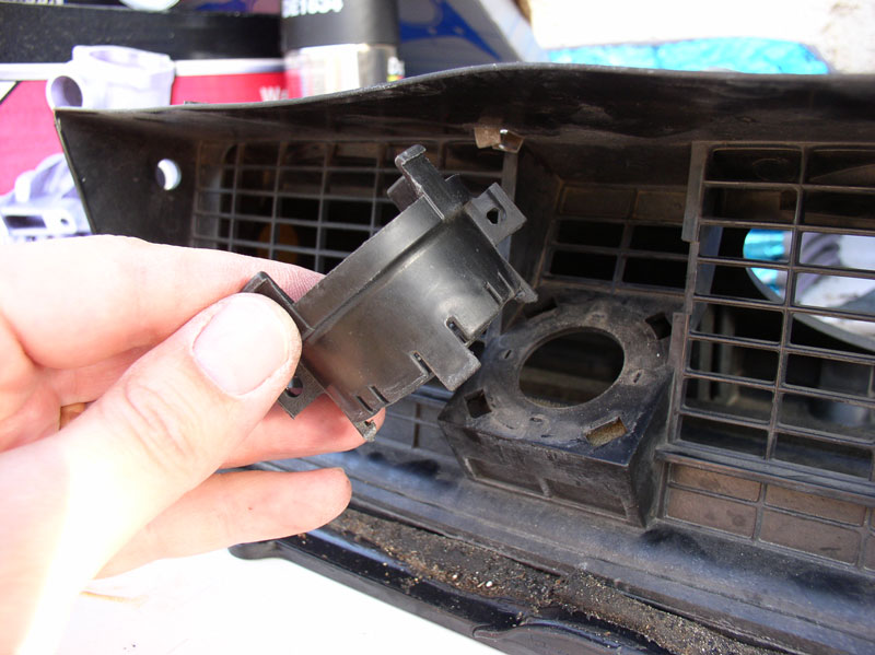
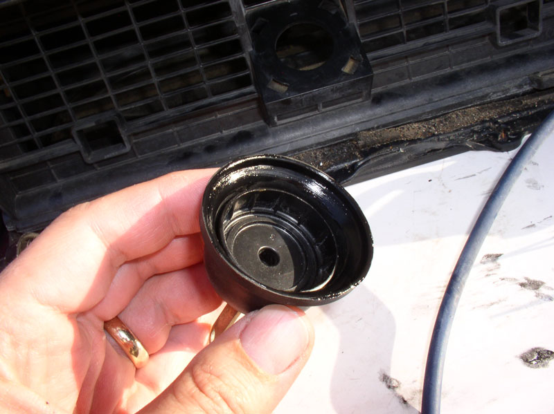
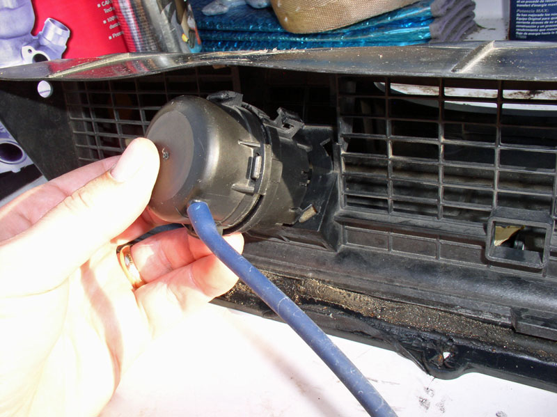
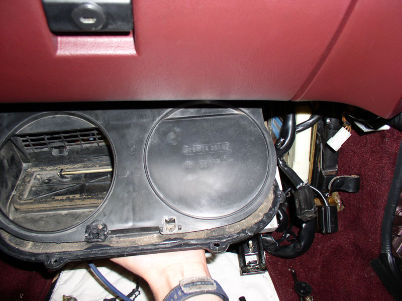
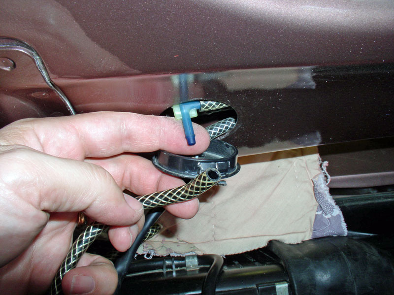
The recirculation box uses a flap that has a binary operation � either up or down. In the at-rest position, the door is down as shown below. In the down position, the door allows fresh air to be drawn in from outside as indicated by the green arrows below. When vacuum is applied to the actuator, it raises the door up blocking the outside air opening. This leaves an opening in the bottom of the recirculation box and allows air to be drawn in from inside the cabin above the passenger�s foot well.
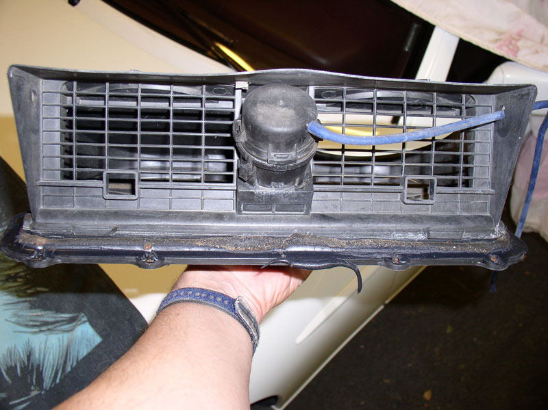
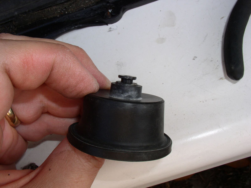
Here�s a picture of the vacuum actuator that had a vacuum leak on our car.
Continued...
We will need to remove the two CEB support brackets and lower them out of the way. I started by removing the upper nut on both brackets.
I don�t believe it is required to disconnect the CEB from it�s support brackets in order to remove the recirculation box. However, I wanted maximum maneuverability when removing the recirculation box so decided to disconnect the CEB from it�s support brackets which is as simple as removing a couple of screws. I removed the left and right Phillips screws as shown below.
You will also need to remove the 10mm bolt securing the support bracket to the floor board. Remove the bolt for the other bracket as well.
At this point, I could easily lift up on the bracket and pull it forward as shown below.
Although not necessary, I found the left bracket easy enough to remove altogether.
The right bracket isn�t so easy to fully remove so I left it in place but lifted it up and out in the same manner as the right bracket and only moved it down enough to be out of the way as pictured below.
Remove the remaining two 10mm nuts on the forward edge of the recirculation box and the metal support bar can be removed � see below.
Remove the remaining four 10mm nuts around the sides and rearward edge of the recirculation box.
The only thing securing the recirculation box to the body at this point is the sealant to prevent water leakage. I pressed down on the box from above with only enough force to break the seal and free the box.
Maneuver the box down into the foot well from above.
From underneath the glove box, continue maneuvering the box out.
And remove it from the car.
The recirculation box uses a flap that has a binary operation � either up or down. In the at-rest position, the door is down as shown below. In the down position, the door allows fresh air to be drawn in from outside as indicated by the green arrows below. When vacuum is applied to the actuator, it raises the door up blocking the outside air opening. This leaves an opening in the bottom of the recirculation box and allows air to be drawn in from inside the cabin above the passenger�s foot well.
Here�s a picture of the vacuum actuator that had a vacuum leak on our car.
Continued...
01-02-2011, 09:39 PM
#66
Three Wheelin'
Thread Starter
Join Date: Sep 2007
Location: Ridgecrest, California
Posts: 1,363
Likes: 0
Received 146 Likes
on
30 Posts
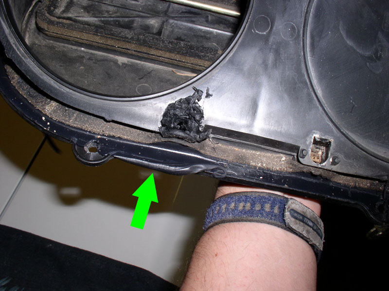
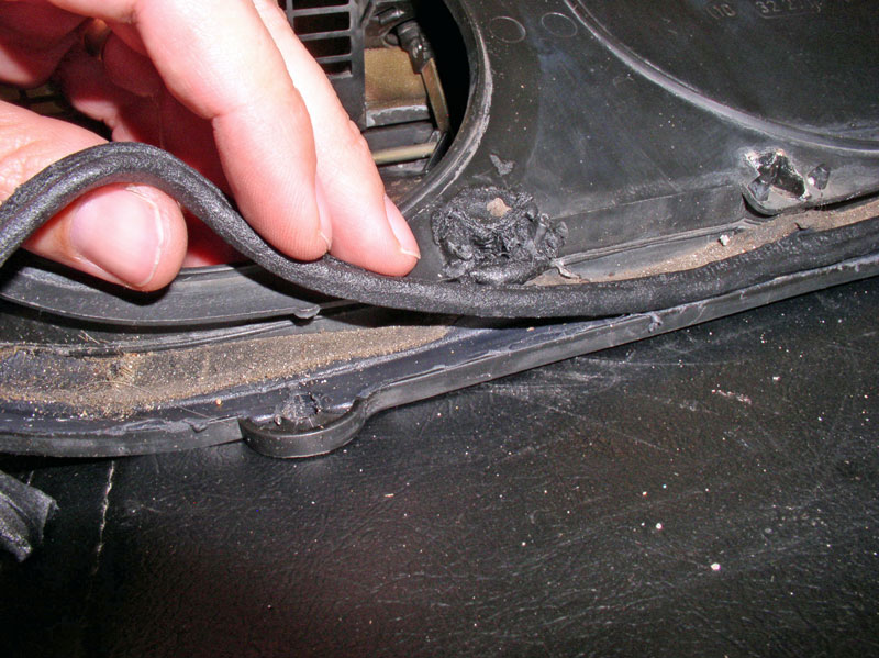
Around the edge of the box, you may notice a non-hardening, water-proof sealant that is intended to keep water from leaking into the cabin foot well area and possibly leaking down in to the CEB area.
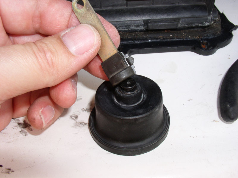
Now we�re ready to operate on the actuator diaphragm. On my next repair of this type, I will follow an improved process for removing the actuator from the recirculation box. Since this was my first attempt at this repair, I documented by �learning� experience and now you can learn with me! I�ll reveal an easier way to get the diaphragm out after I explain what I did the harder way. Both ways work. First, notice the top of the actuator is secured with 4 plastic locking tabs. These will need to be pressed in to release the top.
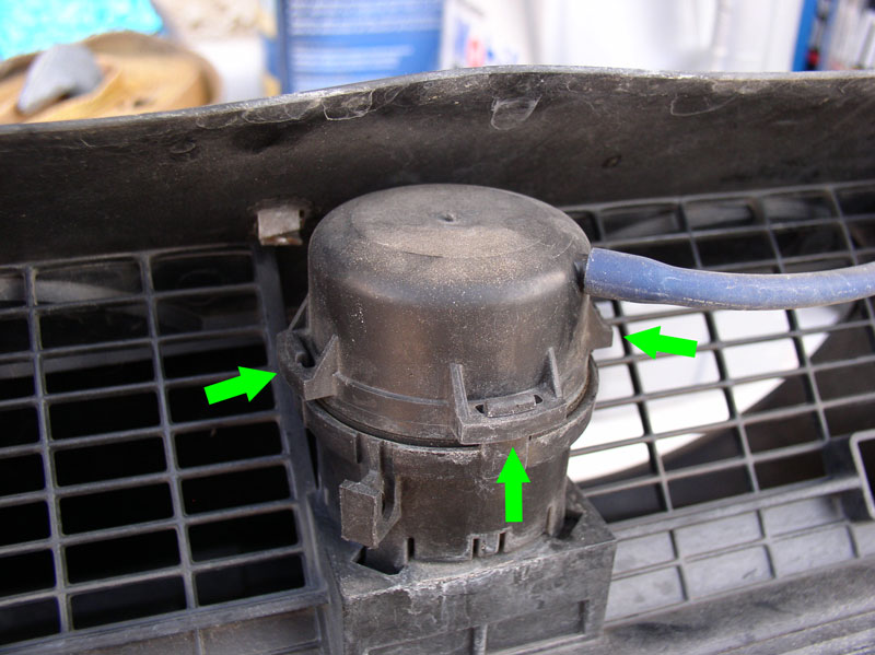
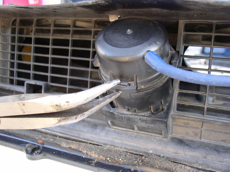
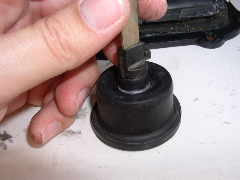
I used a pair of needle nose pliers to press in and down on each tab to disengage the lock. I did this for the three accessible tabs. The fourth tab is on the back side not accessible with the actuator mounted to the box but it will come loose easily when the other 3 are unlocked.
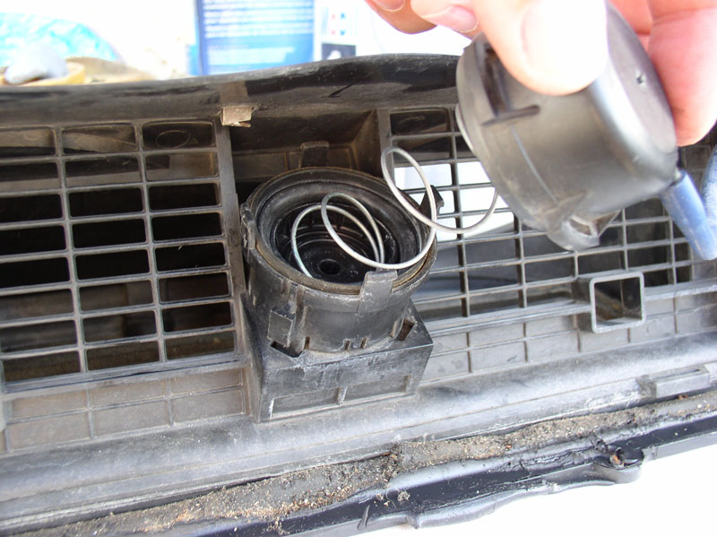
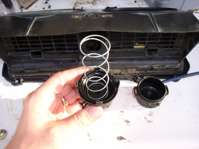
When the lock tabs are disengaged, remove the top keeping in mind the top is under spring pressure. Remove the spring as well noting that the wider end of the spring is oriented up (into the top of the actuator housing).
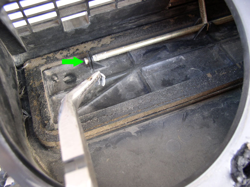
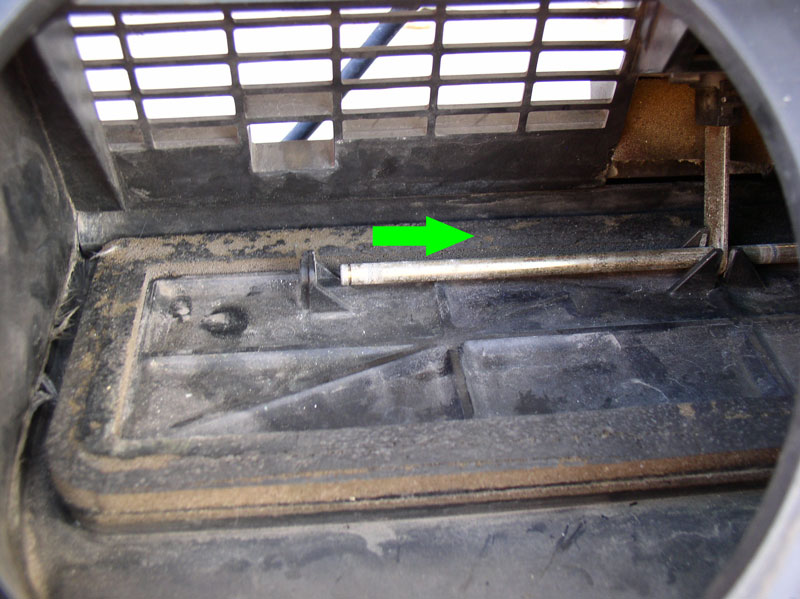
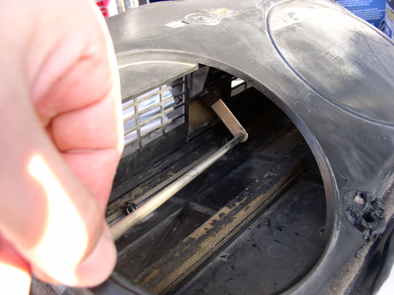
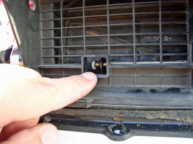
Before you can remove the diaphragm from the actuator housing, you will need to disengage the lever arm from the pivot bar. From the blower access port, use a pair of needle nose pliers to remove the clip on the end of the pivot bar as shown below.
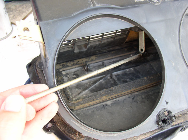
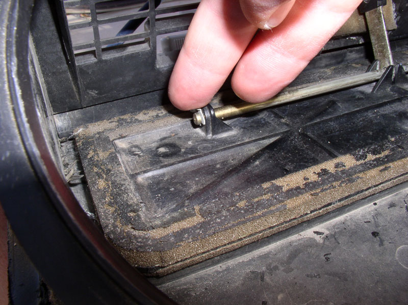
From the front of the box, use the small access port to get at the clip on the opposite end of the pivot bar and remove the clip.
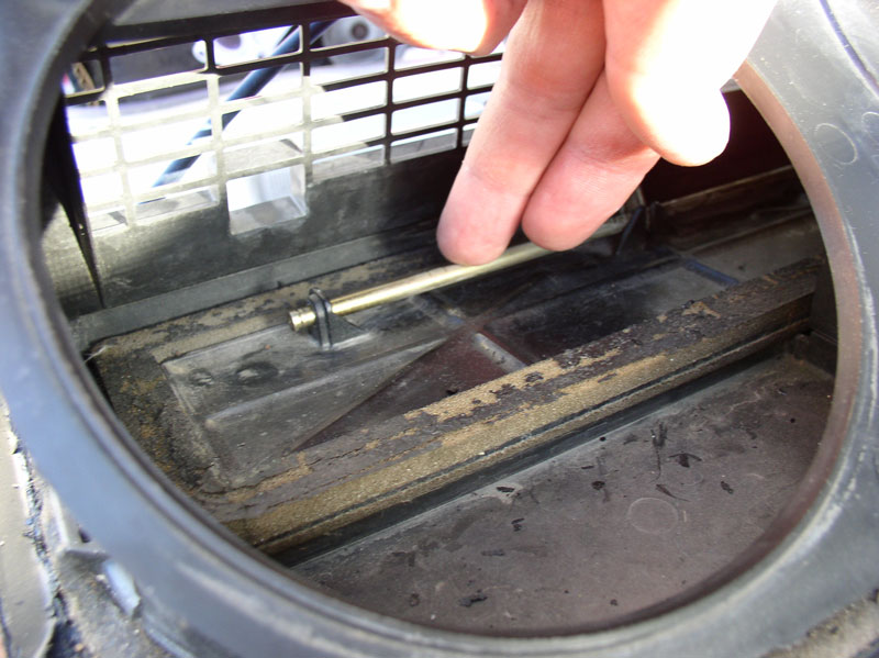
Slide the pivot bar in the direction of the arrow just enough to clear the left most mounting bracket as shown.
Then slightly lift up and pull the pivot bar to the left and maneuver it out of the recirculation box as shown below.
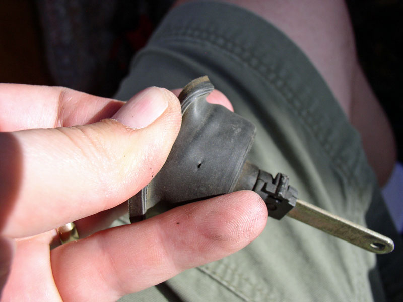
You can now lift out the vacuum diaphragm and lever arm.
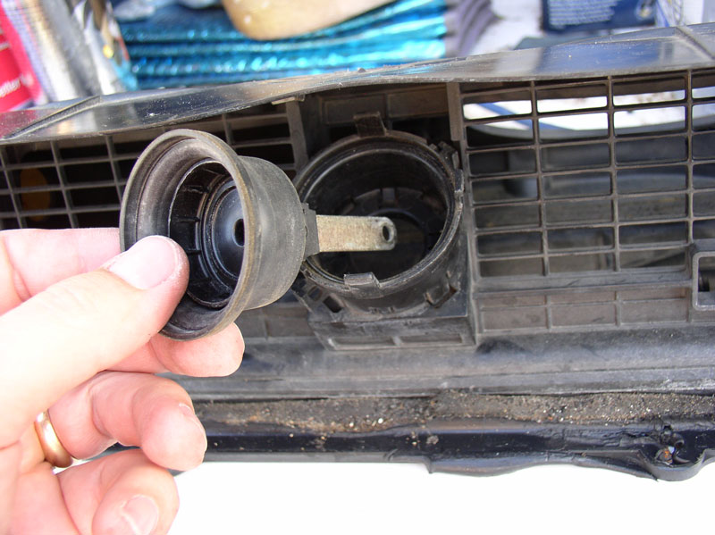
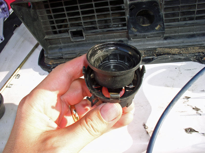
Now, for that alternate method I promised. Before removing the top of the actuator casing (a few pictures back), remove the pivot bar as depicted above (remove the clips at the ends of the bar and maneuver the bar out as described). At this point you can remove the entire actuator from the recirculation box before separating the top as I described first. The bottom half of the actuator casing is locked into the recirculation box with plastic tabs as well. Carefully pry the lower locking tabs away from the recirculation box and the actuator will come free. You can then remove the top of the actuator as previously described but you will now have full access to all four locking tabs. Either way, the lower half of the actuator casing must come out of the recirculation box. See below.
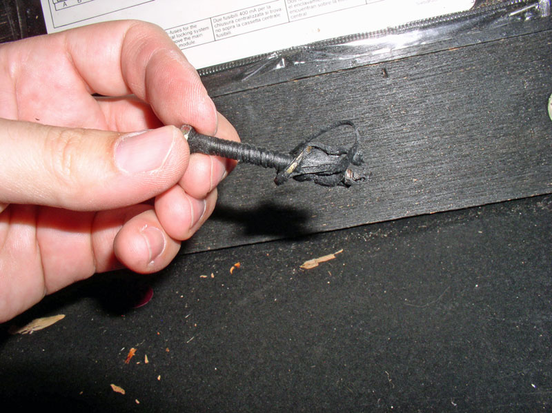
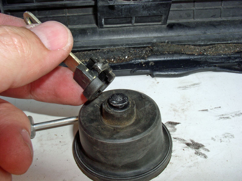
If you were experiencing a vacuum lead with this actuator and you have an inquiring mind, you can inspect the diaphragm for holes. Found it � below.
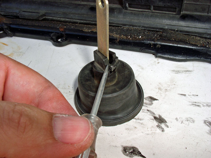
To remove the diaphragm from the lever arm, you will need to carefully pry the locking tab apart as indicated in the picture below. I would not try to pry the screwdriver against the lever arm as this may break the small lock tab.
Remove the lever arm and clamp as shown below.
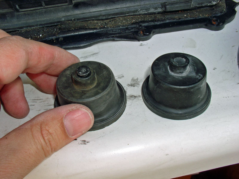
I compared the old diaphragm and new diaphragm � look identical!
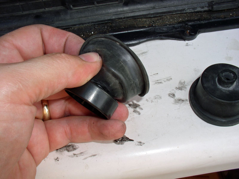
Remove the old diaphragm from the plastic base by peeling it backward.
Continued....
Now we�re ready to operate on the actuator diaphragm. On my next repair of this type, I will follow an improved process for removing the actuator from the recirculation box. Since this was my first attempt at this repair, I documented by �learning� experience and now you can learn with me! I�ll reveal an easier way to get the diaphragm out after I explain what I did the harder way. Both ways work. First, notice the top of the actuator is secured with 4 plastic locking tabs. These will need to be pressed in to release the top.
I used a pair of needle nose pliers to press in and down on each tab to disengage the lock. I did this for the three accessible tabs. The fourth tab is on the back side not accessible with the actuator mounted to the box but it will come loose easily when the other 3 are unlocked.
When the lock tabs are disengaged, remove the top keeping in mind the top is under spring pressure. Remove the spring as well noting that the wider end of the spring is oriented up (into the top of the actuator housing).
Before you can remove the diaphragm from the actuator housing, you will need to disengage the lever arm from the pivot bar. From the blower access port, use a pair of needle nose pliers to remove the clip on the end of the pivot bar as shown below.
From the front of the box, use the small access port to get at the clip on the opposite end of the pivot bar and remove the clip.
Slide the pivot bar in the direction of the arrow just enough to clear the left most mounting bracket as shown.
Then slightly lift up and pull the pivot bar to the left and maneuver it out of the recirculation box as shown below.
You can now lift out the vacuum diaphragm and lever arm.
Now, for that alternate method I promised. Before removing the top of the actuator casing (a few pictures back), remove the pivot bar as depicted above (remove the clips at the ends of the bar and maneuver the bar out as described). At this point you can remove the entire actuator from the recirculation box before separating the top as I described first. The bottom half of the actuator casing is locked into the recirculation box with plastic tabs as well. Carefully pry the lower locking tabs away from the recirculation box and the actuator will come free. You can then remove the top of the actuator as previously described but you will now have full access to all four locking tabs. Either way, the lower half of the actuator casing must come out of the recirculation box. See below.
If you were experiencing a vacuum lead with this actuator and you have an inquiring mind, you can inspect the diaphragm for holes. Found it � below.
To remove the diaphragm from the lever arm, you will need to carefully pry the locking tab apart as indicated in the picture below. I would not try to pry the screwdriver against the lever arm as this may break the small lock tab.
Remove the lever arm and clamp as shown below.
I compared the old diaphragm and new diaphragm � look identical!
Remove the old diaphragm from the plastic base by peeling it backward.
Continued....
01-02-2011, 09:46 PM
#67
Three Wheelin'
Thread Starter
Join Date: Sep 2007
Location: Ridgecrest, California
Posts: 1,363
Likes: 0
Received 146 Likes
on
30 Posts
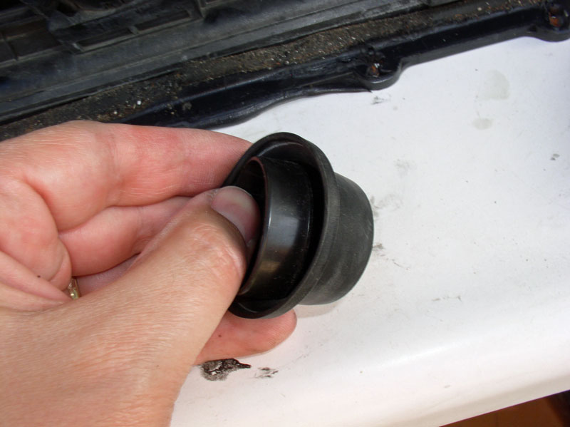
Place the plastic base into the new diaphragm as depicted in the picture below.
Ensure the plastic base is fully seated at the bottom of the diaphragm so the mounting flange is fully visible out the bottom of the diaphragm as shown I the pic below.
Re-install the lever arm and clamp.
Lock the clamp into place ensuring the locking tab is engaged as shown below.
To help ensure a pinch-free, distortion-free fit of the diaphragm in the actuator casing, I applied a light coat of silicone lubricant to the inside lip of the diaphragm. This helped the top cover of the actuator casing fit inside the diaphragm without pinching or binding the diaphragm.
Place the diaphragm in the bottom half of the actuator casing as shown.
Place the spring inside the diaphragm with small end down as shown.
Install the top cover of the actuator casing ensuring the diaphragm is not pinched or distorted all around. Press the top down until all 4 locking tabs are engaged.
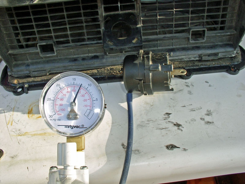
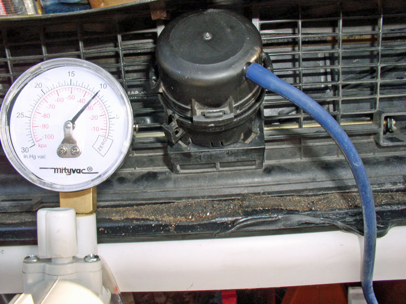
Test the actuator by hooking it up to the vacuum pump and testing for leaks and proper operation. Everything checked out here!
Install the actuator into the front of the recirculation box lining up the locking tabs and pressing the actuator down until all locking tabs are engaged. Orient the actuator so the vacuum port is facing the right and downward (about the 4:30 location as your are looking at the fresh air inlet side of the recirculation box. See picture below.
Re-install the pivot bar by first sliding it through the vacuum actuator lever arm as shown.
Continue sliding the pivot bar into the mounting tab at the far right of the box. Then slide the bar back to the left and insert the other end through the mounting tab as shown below.
Install the locking clip on the end of the pivot bar as shown below.
Install the other locking clip at the opposite end of the pivot bar � see pic below.
Test the operation of the vacuum actuator using the vacuum pump. You should see the door close and block the fresh air inlet when vacuum is applied. Note the amount of vacuum needed to fully close the flap.
Continued....
Ensure the plastic base is fully seated at the bottom of the diaphragm so the mounting flange is fully visible out the bottom of the diaphragm as shown I the pic below.
Re-install the lever arm and clamp.
Lock the clamp into place ensuring the locking tab is engaged as shown below.
To help ensure a pinch-free, distortion-free fit of the diaphragm in the actuator casing, I applied a light coat of silicone lubricant to the inside lip of the diaphragm. This helped the top cover of the actuator casing fit inside the diaphragm without pinching or binding the diaphragm.
Place the diaphragm in the bottom half of the actuator casing as shown.
Place the spring inside the diaphragm with small end down as shown.
Install the top cover of the actuator casing ensuring the diaphragm is not pinched or distorted all around. Press the top down until all 4 locking tabs are engaged.
Test the actuator by hooking it up to the vacuum pump and testing for leaks and proper operation. Everything checked out here!
Install the actuator into the front of the recirculation box lining up the locking tabs and pressing the actuator down until all locking tabs are engaged. Orient the actuator so the vacuum port is facing the right and downward (about the 4:30 location as your are looking at the fresh air inlet side of the recirculation box. See picture below.
Re-install the pivot bar by first sliding it through the vacuum actuator lever arm as shown.
Continue sliding the pivot bar into the mounting tab at the far right of the box. Then slide the bar back to the left and insert the other end through the mounting tab as shown below.
Install the locking clip on the end of the pivot bar as shown below.
Install the other locking clip at the opposite end of the pivot bar � see pic below.
Test the operation of the vacuum actuator using the vacuum pump. You should see the door close and block the fresh air inlet when vacuum is applied. Note the amount of vacuum needed to fully close the flap.
Continued....
01-02-2011, 10:01 PM
#68
Three Wheelin'
Thread Starter
Join Date: Sep 2007
Location: Ridgecrest, California
Posts: 1,363
Likes: 0
Received 146 Likes
on
30 Posts
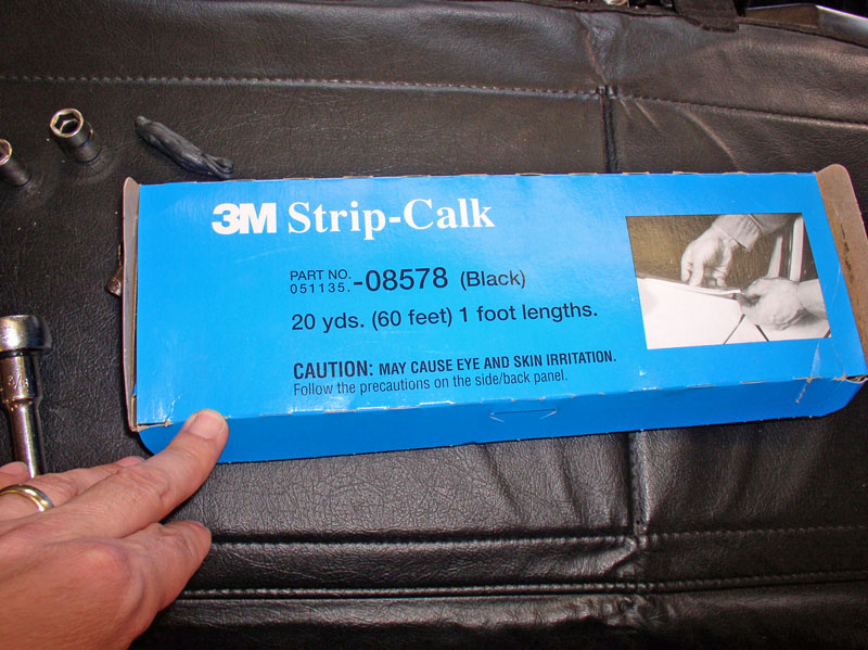
The recirculation box is now ready to re-install back into the car. Before putting it back into the car, It�s a good idea to renew the non-hardening, water-proof seal around the box. I used the 3M Automotive Strip-Calk pictured below � works great!
Apply a bead of the calk around the perimeter of the recirculation box as shown.
Maneuver the unit back under the glove box oriented as shown in the picture below.
As you are lifting the box into place, ensure the blue vacuum line is not caught in between the recirculation box and the body.
Press the recirculation box into place over the existing studs.
Install the support bar at the forward edge of the box as shown below.
Maneuver the CEB support bracket into position over the 2nd stud from the left as shown.
Line up the bottom of the bracket with the threads in the floor board and install the 10mm bolt and tighten down..

Install the 10mm nut at the top of the CEB support bracket as shown and tighten down. Repeat for installing the right CEB support bracket.
Install the remaining four 10mm nuts and washers as shown below.

When the recirculation box is tightened all around, I observed small amounts of the sealant ooze out from the edges which I took as a sign of a good seal.
Install the CEB into its support bracket by inserting the pins (one on each end of the CEB) into the respective holes in the support brackets.
Install and tighten down the Phillips screws that secure the top of the CEB to the support bracket.
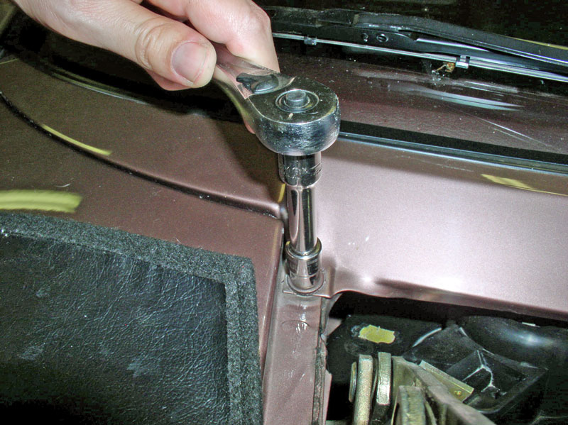
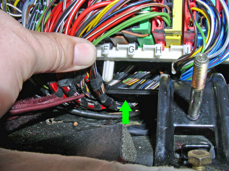
Re-insert the long blower motor screw into its respective hole and begin threading it in.
Only thread the screw in enough so a �� or so protrudes on the upper surface of the recirculation box as indicated below by the green arrow. This small protrusion will help in locating the blower motor casing onto the screw. Ensure there is enough non-hardening sealant surrounding the screw.
Continued....
Apply a bead of the calk around the perimeter of the recirculation box as shown.
Maneuver the unit back under the glove box oriented as shown in the picture below.
As you are lifting the box into place, ensure the blue vacuum line is not caught in between the recirculation box and the body.
Press the recirculation box into place over the existing studs.
Install the support bar at the forward edge of the box as shown below.
Maneuver the CEB support bracket into position over the 2nd stud from the left as shown.
Line up the bottom of the bracket with the threads in the floor board and install the 10mm bolt and tighten down..
Install the 10mm nut at the top of the CEB support bracket as shown and tighten down. Repeat for installing the right CEB support bracket.
Install the remaining four 10mm nuts and washers as shown below.
When the recirculation box is tightened all around, I observed small amounts of the sealant ooze out from the edges which I took as a sign of a good seal.
Install the CEB into its support bracket by inserting the pins (one on each end of the CEB) into the respective holes in the support brackets.
Install and tighten down the Phillips screws that secure the top of the CEB to the support bracket.
Re-insert the long blower motor screw into its respective hole and begin threading it in.
Only thread the screw in enough so a �� or so protrudes on the upper surface of the recirculation box as indicated below by the green arrow. This small protrusion will help in locating the blower motor casing onto the screw. Ensure there is enough non-hardening sealant surrounding the screw.
Continued....
01-02-2011, 10:12 PM
#69
Three Wheelin'
Thread Starter
Join Date: Sep 2007
Location: Ridgecrest, California
Posts: 1,363
Likes: 0
Received 146 Likes
on
30 Posts
I re-installed the blower motor by carefully lifting up on the wiper valance to create enough clearance to drop the motor into place.
I installed the rubber boot while the motor was still free to maneuver.
I installed the �easy� screw first by only starting the threads but not tightening it down. This allowed the motor to be �located� easier to install the remaining harder screws while allowing the motor to maneuver around.
I decided to insert the short screw at the rubber connector next. To help hold the screw into the socket, I applied a small amount of grease to the screw head. This kept the screws attached to the socket while I located the hole.
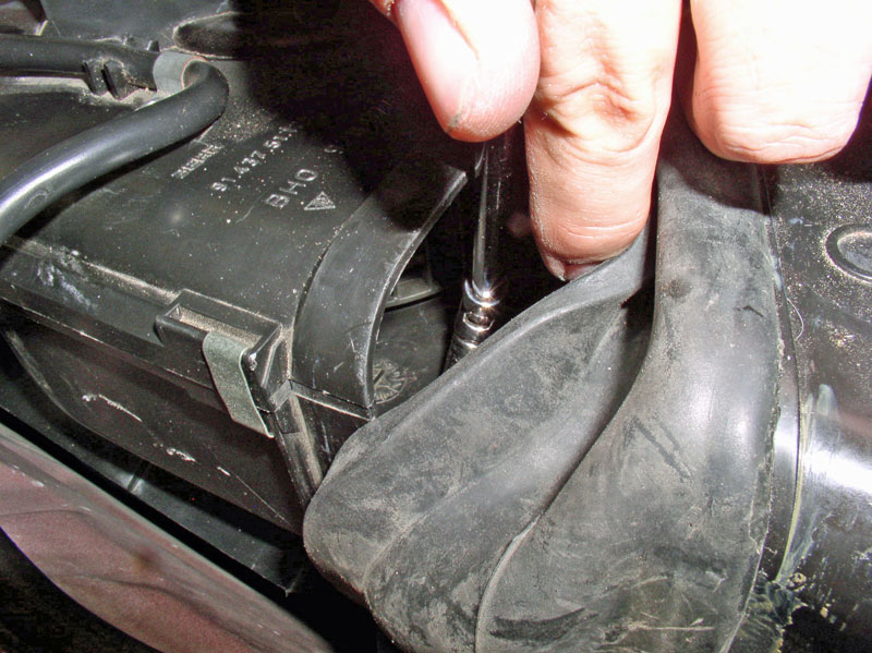
Next, hold back the rubber boot and using a flashlight, locate the hole and install the screw once the holes are aligned.
You should be able to �feel� if the blower motor casing is lined up on the protruding screw installed earlier by slightly moving the motor from side to side. When the protruding screw is lined up with the motor casing hole, go down below and tighten the 8mm screw down.
Then go back up topside and finish tightening both the �easy� screw and the screw under the rubber boot.
Ensure the rubber boot is sealed all around.
Re-install the 10mm bolt that secures the wiper valance to the fender as shown.
Place the wiper arms back on the spindles and align the wiper arms to the proper at-rest position. Then install and tighten the 13mm nut.
Next, you are ready to re-install the hood. Place the protective covering at the left and right hinge points as before.
Bring the hood over and insert it between the two hinges and support it with the closet dowel as before.
Re-install the hood shims in the same orientation as they were removed. Install the two 13mm bolts and hand tighten. Align the hood and hinge to match the marks you made previously and �snug� down the 13mm bolts. Do not tighten fully as you will undoubtedly need to adjust the hood alignment before finishing. Repeat for the hinge on the other side.
Re-connect the 2-wire and 3-wire harness connectors.
Re-attach the washer fluid hose connections at the hood.
Continued....
I installed the rubber boot while the motor was still free to maneuver.
I installed the �easy� screw first by only starting the threads but not tightening it down. This allowed the motor to be �located� easier to install the remaining harder screws while allowing the motor to maneuver around.
I decided to insert the short screw at the rubber connector next. To help hold the screw into the socket, I applied a small amount of grease to the screw head. This kept the screws attached to the socket while I located the hole.
Next, hold back the rubber boot and using a flashlight, locate the hole and install the screw once the holes are aligned.
You should be able to �feel� if the blower motor casing is lined up on the protruding screw installed earlier by slightly moving the motor from side to side. When the protruding screw is lined up with the motor casing hole, go down below and tighten the 8mm screw down.
Then go back up topside and finish tightening both the �easy� screw and the screw under the rubber boot.
Ensure the rubber boot is sealed all around.
Re-install the 10mm bolt that secures the wiper valance to the fender as shown.
Place the wiper arms back on the spindles and align the wiper arms to the proper at-rest position. Then install and tighten the 13mm nut.
Next, you are ready to re-install the hood. Place the protective covering at the left and right hinge points as before.
Bring the hood over and insert it between the two hinges and support it with the closet dowel as before.
Re-install the hood shims in the same orientation as they were removed. Install the two 13mm bolts and hand tighten. Align the hood and hinge to match the marks you made previously and �snug� down the 13mm bolts. Do not tighten fully as you will undoubtedly need to adjust the hood alignment before finishing. Repeat for the hinge on the other side.
Re-connect the 2-wire and 3-wire harness connectors.
Re-attach the washer fluid hose connections at the hood.
Continued....
01-02-2011, 10:23 PM
#70
Three Wheelin'
Thread Starter
Join Date: Sep 2007
Location: Ridgecrest, California
Posts: 1,363
Likes: 0
Received 146 Likes
on
30 Posts
Re-attach the wire harness ties as before.
Re-install the rain cover being careful to maneuver around the wiring and washer fluid hoses. Ensure the rearward edge of the cover is properly mounted and slides between the valance and the 3 support tabs under the valance. Re-connect the hood shocks by simply pressing the end back onto the ball connector. You may want to remove the service covers next to finish aligning the hood. Once the hood is aligned, perform final tightening of the four 13mm hinge bolts.
Down below, re-install the lower CEB foot rest panel and attach with the two 10mm nuts.
Align the upper CEB cover door and foot rest with the mounting holes on the CEB brackets and tighten down the bolts. At this point, you can re-install the under dash trays for both driver and passenger sides if desired. On my daily driver, I left them off because it gives me extra leg room. On my wife's daily driver, I re-installed them since she doesn't need the extra room. The installation is the reverse of what was documented at the beginning of this post.
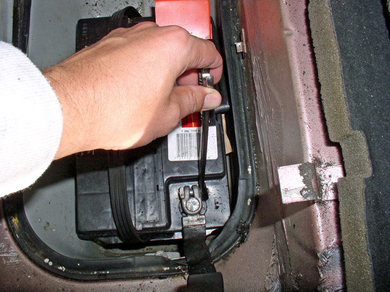
Re-connect the negative battery terminal and button up the rear hatch area.
CONGRATULATIONS! YOU�RE DONE!! Now you can start the car and try out your newly repaired HVAC air distribution/temperature control system.
If you determined that you had a leaking defroster flap actuator, you will need to remove the instrumentation pod to get to it. Here is a step-by-step procedure to removing the pod (http://forums.rennlist.com/rennforum...cs-part-i.html). Since you do not need to disassemble the pod in order to get at the actuator, you can skip the part about removing the control ***** and instrument cluster in the aforementioned post. Simply pull the pod toward the rear of the car and rotate face down over the steering column to give you space to work. Once the pod is pulled over the steering column, you can easily access the defroster actuator.
Please feel free to comment or provide improvement suggestions on this post - I'm always looking for ways to improve the quality of these write ups. THANKS for reading!
Re-install the rain cover being careful to maneuver around the wiring and washer fluid hoses. Ensure the rearward edge of the cover is properly mounted and slides between the valance and the 3 support tabs under the valance. Re-connect the hood shocks by simply pressing the end back onto the ball connector. You may want to remove the service covers next to finish aligning the hood. Once the hood is aligned, perform final tightening of the four 13mm hinge bolts.
Down below, re-install the lower CEB foot rest panel and attach with the two 10mm nuts.
Align the upper CEB cover door and foot rest with the mounting holes on the CEB brackets and tighten down the bolts. At this point, you can re-install the under dash trays for both driver and passenger sides if desired. On my daily driver, I left them off because it gives me extra leg room. On my wife's daily driver, I re-installed them since she doesn't need the extra room. The installation is the reverse of what was documented at the beginning of this post.
Re-connect the negative battery terminal and button up the rear hatch area.
CONGRATULATIONS! YOU�RE DONE!! Now you can start the car and try out your newly repaired HVAC air distribution/temperature control system.
If you determined that you had a leaking defroster flap actuator, you will need to remove the instrumentation pod to get to it. Here is a step-by-step procedure to removing the pod (http://forums.rennlist.com/rennforum...cs-part-i.html). Since you do not need to disassemble the pod in order to get at the actuator, you can skip the part about removing the control ***** and instrument cluster in the aforementioned post. Simply pull the pod toward the rear of the car and rotate face down over the steering column to give you space to work. Once the pod is pulled over the steering column, you can easily access the defroster actuator.
Please feel free to comment or provide improvement suggestions on this post - I'm always looking for ways to improve the quality of these write ups. THANKS for reading!
 01-06-2011, 01:54 AM
#72
Rennlist Member
In addition I replaced the old foam seals on booth side of the large flapper valve by cutting a corner of the housing and re-inserted the cut out secured by 1" wide aluminium strips