






Stroker tech
Addict
Rennlist Member
Rennlist Member

Joined: Jun 2002
Posts: 3,322
Likes: 32

I'm sorry I don't get it, I just looked at my genuine porsche rods and new Chevy "honda style" rods and when I measure the offset "the place where they will sit in the piston pin" mine if they are different to the Porsche rods, it would be out by 0.15 mm max. "My hand held tools don't allow for greater accuracy at this stage but it would be very close" Now maybe the Nascar rods have different offsets as they do not come out of a standard small block chevy, they come out of the Chevy SB2.2.
If this potential 0.15 mm is what we are talking about I can't see how thousands of pounds are transmitted because of this, which what I describe as minor variance? Remember there is that much side clearance minimum, the Porsche spec is 0.1 mm to 0.4 mm my clearance specified by Moldex not me was 0.5 mm. I take it you guys have turned you rods around? If you haven't done this you will be miles out and I understand what Greg is on about. That is the wide fillets of the rods to the inside. You then need to have chamfer added to what was the inside of the rod so that it doesn't wear on the radius of the crank journal.
Maybe somebody can enlighten me?
Greg
If this potential 0.15 mm is what we are talking about I can't see how thousands of pounds are transmitted because of this, which what I describe as minor variance? Remember there is that much side clearance minimum, the Porsche spec is 0.1 mm to 0.4 mm my clearance specified by Moldex not me was 0.5 mm. I take it you guys have turned you rods around? If you haven't done this you will be miles out and I understand what Greg is on about. That is the wide fillets of the rods to the inside. You then need to have chamfer added to what was the inside of the rod so that it doesn't wear on the radius of the crank journal.
Maybe somebody can enlighten me?
Greg
Originally Posted by GregBBRD
The length is indeed correct. Don't use a Chevy design rod, however.
The Chevy rod application is one of those "left over" ideas, from the very beginning of 928 stroker technology, that is now very obsolete. It's one of those things that everyone just accepted and kept doing...over and over again. Turns out that the Chevy rod has the completely wrong offset for the 928 engine, which puts thousands of pounds of side thrust onto the piston. This force thrusts the piston into the cylinder wall and causes the piston pin and rod bearings to have abnormal wear, due to the side loading. This offset issue beats the crap out of the cylinder walls, especially when using the Alusil technology. Our original stroker engines escaped this problem, because we were using a 928 rod, with a slightly different stroke, than is commonly used.
We and Carrillo did extensive research and development with this issue. The side loading numbers are incredible (I have a copy of the engineering data, if anyone wants to see it.) The end result is that Carrillo developed us a proprietary custom H beam rod, just for the 928 engine, that has the correct offset and is as light as their "A" beam rod. It solves all the issues that were created by using the improper offset rod in our 928 application.
We've now used up 10 sets of these "new" rods in stroker applications. The cylinders, the rods, and the bearings are now much happier.
The length is indeed correct. Don't use a Chevy design rod, however.
The Chevy rod application is one of those "left over" ideas, from the very beginning of 928 stroker technology, that is now very obsolete. It's one of those things that everyone just accepted and kept doing...over and over again. Turns out that the Chevy rod has the completely wrong offset for the 928 engine, which puts thousands of pounds of side thrust onto the piston. This force thrusts the piston into the cylinder wall and causes the piston pin and rod bearings to have abnormal wear, due to the side loading. This offset issue beats the crap out of the cylinder walls, especially when using the Alusil technology. Our original stroker engines escaped this problem, because we were using a 928 rod, with a slightly different stroke, than is commonly used.
We and Carrillo did extensive research and development with this issue. The side loading numbers are incredible (I have a copy of the engineering data, if anyone wants to see it.) The end result is that Carrillo developed us a proprietary custom H beam rod, just for the 928 engine, that has the correct offset and is as light as their "A" beam rod. It solves all the issues that were created by using the improper offset rod in our 928 application.
We've now used up 10 sets of these "new" rods in stroker applications. The cylinders, the rods, and the bearings are now much happier.
Last edited by slate blue; Jan 3, 2009 at 06:09 PM.
Rennlist Member
Joined: May 2001
Posts: 4,871
Likes: 41
From: Puyallup, WA
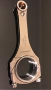
Just FYI, here's a (crappy phone) pic of one of my Oliver rods next to the Porsche Unit for comparison. I was hoping to get a stock SBC rod in the mix, but the motor at the shop hasn't been torn down yet. I got my rods from Motorsport SLC, so Garrity could chime in as to whether these differ from stock SBC rods. I'm assuming that they don't, and are just SBC rods with a reamed and bushed small end.

Rennlist Member
Joined: May 2001
Posts: 4,871
Likes: 41
From: Puyallup, WA
From the angle it's hard to see, but the small end opening is offset in the small end compared to the Porsche rod which has the wrist pin hole dead center in the casting. My wrist pin hole is north of dead center. From a prior thread someone put forward that this design minimizes piston slap.

Three Wheelin'
Joined: Jan 2004
Posts: 1,611
Likes: 13
From: Mosier, Oregon
From the angle it's hard to see, but the small end opening is offset in the small end compared to the Porsche rod which has the wrist pin hole dead center in the casting. My wrist pin hole is north of dead center. From a prior thread someone put forward that this design minimizes piston slap.
As luck would have it, I took some pics of mine too. The small end of the Oliver rod has the bushing in the center just like the 928 rod. I thought Greg was meaning misalignment of the small end longitudinally on the pin. I mean the rod small end would be over to one side of the pin next to the piston. Maybe because the Chevy size big ends are not as wide as the 928 rods and when the narrower rods are on the (narrower) crank throw they wouldn't quite line up with the pistons. I have a pic of the underside of one of my pistons with the engine assembled and the rod small end is right in the middle of the pin. I guess the bottom line is I don't know what the problem really is and don't know enough to know what I don't know.
https://rennlist.com/forums/attachme...1&d=1231117398
https://rennlist.com/forums/attachme...1&d=1231117398
Last edited by Louie928; Jun 13, 2013 at 05:13 PM.
Rennlist Member
Joined: May 2001
Posts: 4,871
Likes: 41
From: Puyallup, WA
It's interesting that your wrist pins are centered. I remember when I posted pics of my rods awhile back Marc Thomas inquired as to why mine were off-centered. It makes sense now why he asked, he was curious since the ones in your motor are centered just like the stockers. I mounted some of my pistons into the stroker block today to measure for head gaskets. I can take a pic of the underside so you can see the rod/pin/piston orientation.
I agree though, if my motor is the poster child for the side loading issue that Greg has designed a fix for, I don't think I want to know about it. Let's face it, its a Porsche, it only makes sense that the motor will do everything possible to force itself into a horizontally opposed engine configuration. LOL.
I agree though, if my motor is the poster child for the side loading issue that Greg has designed a fix for, I don't think I want to know about it.
Let's face it, its a Porsche, it only makes sense that the motor will do everything possible to force itself into a horizontally opposed engine configuration. LOL.
Last edited by atb; Jan 5, 2009 at 12:05 PM.
Three Wheelin'
Joined: Jan 2004
Posts: 1,611
Likes: 13
From: Mosier, Oregon
It's interest that your wrist pins are centered. I remember when I posted pics of my rods awhile back Marc Thomas inquired as to why mine were off-centered. It makes sense now why he asked, he was curious since the ones in your motor are centered just like the stockers. I mounted some of my pistons into the stroker block today to measure for head gaskets. I can take a pic of the underside so you can see the rod/pin/piston orientation.
I agree though, if my motor is the poster child for the side loading issue that Greg has designed a fix for, I don't think I want to know about it. Let's face it, its a Porsche, it only makes sense that the motor will do everything possible to force itself into a horizontally opposed engine configuration. LOL.
I agree though, if my motor is the poster child for the side loading issue that Greg has designed a fix for, I don't think I want to know about it.
Let's face it, its a Porsche, it only makes sense that the motor will do everything possible to force itself into a horizontally opposed engine configuration. LOL.Rennlist Stories
The Best Porsche Posts for Porsche Enthusiasts
Porsche's Top 5 Most Questionable Naming Decisions
Verdad Gallardo
Pogea Racing's 964 Porsche 911 Reimagination Stands Out in a Crowded Field
Verdad Gallardo
6 Convertible Top MYTHS Most People Don't Understand!
Michael S. Palmer
2026 Porsche 911 Club Coupe is Spectacular, And Everything Wrong with the Porsche Market
Joe Kucinski
Talos Takes Your 991 Porsche 911 GT3 to the Next Level for a Cool $1.13 Million
Verdad Gallardo
9 Vehicles Porsche Helped Engineer that Aren't Porsches
Verdad Gallardo
9 Features and Characteristics That Only Porsche People Understand
Verdad Gallardo
I've Written 500 Rennlist Articles: Here's How Porsche Has Changed Along the Way
Joe Kucinski
10 Most Unnecessary Porsches Ever Built (And Why We Love Them)
Verdad Gallardo
Three Wheelin'
Joined: Jan 2004
Posts: 1,611
Likes: 13
From: Mosier, Oregon

Chronic Tool Dropper
Lifetime Rennlist
Member
Lifetime Rennlist
Member
Joined: Oct 2001
Posts: 20,506
Likes: 566
From: Bend, Oregon
 I must be missing something here. The pin-to-big end spacing seems like it would be critical of course. If the pin is not aligned with the center of the beam, the rod beam would just live a little offset from the thrust. I guess I'm not able to visualise how this would affect side loading on the piston. Greg or anybody, straighten me out please.

Former Vendor
Joined: Feb 2005
Posts: 15,228
Likes: 2,530
From: Anaheim
When the Carrillo Chevy rods sit on the crank journals, the wrist pin is not centered under the piston...there is offset of .042". I never tried to turn the Chevy rods around...that would make a "double champher" and part of the rod bearing would sit in the unused inboard champher, it would seem.
I had a set of "Oliver Chevy" rods....on a Scat Crank that came from Marc Thomas, originally. These seemed to center better than the Carrillo rods. Perhaps Marc ordered these rods with a different offset or the cranks were made with the journals in a slightly different location to compensate. Perhaps he might shed some light on this. It would seem that both Carrillo and Olliver should make their Chevy rods with the same offset, since this is a bore spacing measurement and should not vary.
I had a set of "Oliver Chevy" rods....on a Scat Crank that came from Marc Thomas, originally. These seemed to center better than the Carrillo rods. Perhaps Marc ordered these rods with a different offset or the cranks were made with the journals in a slightly different location to compensate. Perhaps he might shed some light on this. It would seem that both Carrillo and Olliver should make their Chevy rods with the same offset, since this is a bore spacing measurement and should not vary.
Three Wheelin'
Joined: Jan 2004
Posts: 1,611
Likes: 13
From: Mosier, Oregon
When the Carrillo Chevy rods sit on the crank journals, the wrist pin is not centered under the piston...there is offset of .042". I never tried to turn the Chevy rods around...that would make a "double champher" and part of the rod bearing would sit in the unused inboard champher, it would seem.
I had a set of "Oliver Chevy" rods....on a Scat Crank that came from Marc Thomas, originally. These seemed to center better than the Carrillo rods. Perhaps Marc ordered these rods with a different offset or the cranks were made with the journals in a slightly different location to compensate. Perhaps he might shed some light on this. It would seem that both Carrillo and Olliver should make their Chevy rods with the same offset, since this is a bore spacing measurement and should not vary.
I had a set of "Oliver Chevy" rods....on a Scat Crank that came from Marc Thomas, originally. These seemed to center better than the Carrillo rods. Perhaps Marc ordered these rods with a different offset or the cranks were made with the journals in a slightly different location to compensate. Perhaps he might shed some light on this. It would seem that both Carrillo and Olliver should make their Chevy rods with the same offset, since this is a bore spacing measurement and should not vary.
https://rennlist.com/forums/attachme...1&d=1231131963
Last edited by Louie928; Jun 13, 2013 at 05:13 PM.


Three Wheelin'
Joined: Jan 2007
Posts: 1,466
Likes: 0
From: not where you think I am
the picture that Louie has posted gives you an idea of where the rod /piston relationship should be--
the small end of the rod should be centered on the pin in the center of the piston. if not, the piston may exhibit wear (on one side) above the pin and (on the other side) below the pin, depending which side of the piston the rod offset is, assuming the piston was properly manufactured (with rod centering in mind).
Another issue is where the pin hole/crank hole is cut into the rod itself. If the hole (s) is not centered on the rod (offset when looking at the open hole in relation to beam center), it will make one side of the rod weaker and side load the piston on the sides perpendicular to the length of the piston pin.
the point to all of this, is that your crank supplier must know the measurements of your rods (the thickness of the big end of the rod times two, and the spacings between the vertical centers of the beam) and your bore spacings on each side and the bore spacings between opposing sides, to properly position the rods on the crank so that they are on bore center. Similarly, the vertical centers of the rod beams (when places together in pairs) must also be the exact measurement of the opposing bore centers. all of these measurements must match.
if not, your pistons may have a side load issue and contribute to excessive cylinder/piston skirt wear.
O O O O
l
lO O O O
l l
^ this is the bore to bore measurement you need (bore center to bore center of opposing cylinders)
H H
l l
l l
l l
lllHlllHlll
^--^ this is the rod vertical beam center measurements between two paired rods on a crank throw that you need
(OK, this is weird, I typed these drawings and they didn't come out right when I submitted the post, nor will they edit correctly. hopefully, you get the idea.)
These two measurements must match.
Of course, none of this takes into account flame travel across the piston top and its forces that are unevenly distributed on the piston, which does cause some side loading and wear.
It's all in the math and the measurements-----
--Russ
the small end of the rod should be centered on the pin in the center of the piston. if not, the piston may exhibit wear (on one side) above the pin and (on the other side) below the pin, depending which side of the piston the rod offset is, assuming the piston was properly manufactured (with rod centering in mind).
Another issue is where the pin hole/crank hole is cut into the rod itself. If the hole (s) is not centered on the rod (offset when looking at the open hole in relation to beam center), it will make one side of the rod weaker and side load the piston on the sides perpendicular to the length of the piston pin.
the point to all of this, is that your crank supplier must know the measurements of your rods (the thickness of the big end of the rod times two, and the spacings between the vertical centers of the beam) and your bore spacings on each side and the bore spacings between opposing sides, to properly position the rods on the crank so that they are on bore center. Similarly, the vertical centers of the rod beams (when places together in pairs) must also be the exact measurement of the opposing bore centers. all of these measurements must match.
if not, your pistons may have a side load issue and contribute to excessive cylinder/piston skirt wear.
O O O O
l
lO O O O
l l
^ this is the bore to bore measurement you need (bore center to bore center of opposing cylinders)
H H
l l
l l
l l
lllHlllHlll
^--^ this is the rod vertical beam center measurements between two paired rods on a crank throw that you need
(OK, this is weird, I typed these drawings and they didn't come out right when I submitted the post, nor will they edit correctly. hopefully, you get the idea.)
These two measurements must match.
Of course, none of this takes into account flame travel across the piston top and its forces that are unevenly distributed on the piston, which does cause some side loading and wear.
It's all in the math and the measurements-----
--Russ