
Converting a 928 to Megasquirt. (LONG)
 12-07-2008, 11:36 PM
#1
Nordschleife Master
Thread Starter
I have gotten alot of emails and questions regarding converting my 86 engined 81 to MSII V3.0.
I am going to try to document some of the information here so that it will assist others in making the leap to a newer more efficent system.
Now before I get started I am going to say that if you do the research on MS or any other aftermarket EFI system, the information is VERY VERY overwhelming, and extremely confusing for anyone that has not done it before. Without having it in front of you and following the steps with everything there. Most people stop before they even get to the second page.
What I can tell you is that while it can be abit daunting of a task for most people, it is a VERY worthwhile change to make to your car and you can have countless hours of fun (or pulling your hair out, or maybe a mixture of both for you sadists out there) tinkering with the settings and adjustments.
Now I will say that this conversion will be ALOT easier for non CIS cars but is abit more work for the origonally CIS cars.
So for CIS cars, the largest addition that you are going to have to do to the car is to convert the car from running CIS inj to electric injtors. There are a few ways to do this, some are more efficent than others. The way that I would recommend is not for everyone and this is a very personal choice.
I would buy a plug, or make one to simply plug the origonal CIS inj holes. I would then get an aluminum weld on bung and attach the bung as far away from the valve as I could possibly get. If I was to go for an all out power and not really be worried about idle then I would put the injectors at the very top out most portions of each runner pointing towards the center plenum. But this could cause idle issues Now that is done you have to make your own fuel rail or if you want to be lazy/easy route measure the injector centers and go to the local junkyard and find a fuel injector rail with very close injector centers and use that.
Now onto the main part of the systems, I will start with IGN systems.
You do have alot of options, however I will tell you the two easiest routes to take.
Option #1 You use the factory coil, distributor cap(s) and rotor(s). You can control upto 2 coils with MSII V3.0, you can even use the final stages on the 85+ cars to run the ign system this way. This should be pretty self explanatory. But to put it into laymans turns, the MS unit will fire the coils controlling the ign advance either directly by controlling the ground to the coil, or through the final stages.
Options #2, Now this is THE way to go IMHO as it removes all the moving parts for the IGN system making it much more reliable, less parts for a tune up, and the ability to run a MUCH larger ign gap. The second option is to use EDIS-8.
This system is found on all 1990 to 1997 4.6L V8 engines made by FORD. So you can go to the junkyard and get all the parts VERY cheaply. The only downside about this is that you have to have to get custom leads for the 32V engines, however they can be had at a reasonable price from aurora electronics in Abbotsford BC, Canada.
The next thing you have to think about it how you are going to trigger the MS, meaning you need to figure out how you are going to tell the MS that the engine is turning over. Again I will simplify this, telling you only 2 options, there are MANY more ways to go about this. Again these are based off of the first two options.
Following option #1 You can use the factory trigger ring with the factory sensor, on CIS cars though I would recommend that you choose option #2 right from the get go. Now the other choice here, is using the factory trigger wheel with any either VR or hall sensor. But this will require you to modify the engine to be able to get the sensor close enough to the toothed ring.
Following option #2, EDIS requires the use of a 36-1 toothed ring. 36-1 means that there should be 36 teeth, but one has been cut off. Now here comes the tricky part, you have to mount one of these toothed rings to the crankshaft. I had one waterjet cut that is the same thickness of the AC pulley and replaced the pulley as I dont use AC on the car (hey its the north we live in igloos year round ). You can order the 36-1 toothed rings online very cheaply you can then have a hole cut in the center (or do this yourself) to fit over the base of the accessory pulley. You then slide the ring on and the pulley will center it, then simply give it some strong tack welds to hold it in place and voila mounted. Now you have to mount the EDIS VR sensor which reads these teeth. I used a small piece of steel and attached it to one of the 3 bolt holes on the factory waterpump. Now when you install this modified pulley you do need to pay attention (if you want to be able to start the car easily), the VR sensor must be on the 9th tooth ATDC on the crankshaft. If you get this right you will have a perfect 10 deg ign advance with no changes needing to be made.
Now as I said EDIS is IMO the way to go as you loose the rotating parts, but there is another advantage you are able to run a MUCH larger spark plug gap which can really help idle and peak power areas. With EDIS you can run upto a .060 plug gap, boosted .045.
Now that the main big decisions are looked after the next thing that you need to think about is what you are going to do for coldstart/idle control. I went to a local junkyard and get a PWM idle valve off a VW golf as they are common, look almost the same as the 928S4 valve, but they dont get stuck/gummed up near as easy. You can however use a AAV as is found on all CIS/L-jet cars. But these are not the only options you can pretty much use ANY valve that was ever used on a car to let in extra air for cold starts.
Now that the options are taken care of we need to look at sensors that are needed.
We really need 3 sensors (besides the crank trigger), they are Coolant (CLT) Air intake temp (AIT), and Wideband O2 (WB).
For both the CLT and AIT sensors I would strongly recommend either buying or salvaging GM sensors, a closed air sensor for the coolant and an open one for AIT as it has quicker responce times. These are very easy to mount and all you have to do is enlarge the factory TEMP II hole on later cars, or drill and tap a 3/8 NPT hole on the top of the coolant bridge for the CLT sensor. The AIT sensor is the same idea but in the bottom of the airbox, or in the plumbing running into the throttle body. Now it is best to try to keep this sensor mounted in plastic iff possible to prevent heat soak, but this is not always feasible and not that much of a worry.
Now this would be a good time to note, anyone doing this on a CIS car would be best off redoing the throttle body setup and just cap the hole on the bottom and weld on a flange and punch a hole through to use a domestic throttle body onto the rear off the spider or you will have to try to figure out how to remove the CIS metering unit and adapt the airbox to the plenum.
The last sensor is the WB, this will obviously be able to go right in the factory O2 sensor port, however you will need to get a system such as innovate LC1, or Techedge, AEM etc. They are all about the same, with each having its own quirks.
Now there are a few things which I KNOW I am leaving out, like injectors, but these are things that you have to do your own research and make your own decision on.
Now that you have this information, you can purchase all the items you are wanting to go with. The only other BIG decision you need to make now is if you buy it preassembled, or buy it as a kit and assemble it yourself. I have done both and assembling it myself is rewarding, but very time consuming.
I will end this post here, and in the next post will tell you what you need to buy, and a location or two you can buy them from.
I am going to try to document some of the information here so that it will assist others in making the leap to a newer more efficent system.
Now before I get started I am going to say that if you do the research on MS or any other aftermarket EFI system, the information is VERY VERY overwhelming, and extremely confusing for anyone that has not done it before. Without having it in front of you and following the steps with everything there. Most people stop before they even get to the second page.
What I can tell you is that while it can be abit daunting of a task for most people, it is a VERY worthwhile change to make to your car and you can have countless hours of fun (or pulling your hair out, or maybe a mixture of both for you sadists out there) tinkering with the settings and adjustments.
Now I will say that this conversion will be ALOT easier for non CIS cars but is abit more work for the origonally CIS cars.
So for CIS cars, the largest addition that you are going to have to do to the car is to convert the car from running CIS inj to electric injtors. There are a few ways to do this, some are more efficent than others. The way that I would recommend is not for everyone and this is a very personal choice.
I would buy a plug, or make one to simply plug the origonal CIS inj holes. I would then get an aluminum weld on bung and attach the bung as far away from the valve as I could possibly get. If I was to go for an all out power and not really be worried about idle then I would put the injectors at the very top out most portions of each runner pointing towards the center plenum. But this could cause idle issues
Now that is done you have to make your own fuel rail or if you want to be lazy/easy route measure the injector centers and go to the local junkyard and find a fuel injector rail with very close injector centers and use that. Now onto the main part of the systems, I will start with IGN systems.
You do have alot of options, however I will tell you the two easiest routes to take.
Option #1 You use the factory coil, distributor cap(s) and rotor(s). You can control upto 2 coils with MSII V3.0, you can even use the final stages on the 85+ cars to run the ign system this way. This should be pretty self explanatory. But to put it into laymans turns, the MS unit will fire the coils controlling the ign advance either directly by controlling the ground to the coil, or through the final stages.
Options #2, Now this is THE way to go IMHO as it removes all the moving parts for the IGN system making it much more reliable, less parts for a tune up, and the ability to run a MUCH larger ign gap. The second option is to use EDIS-8.
This system is found on all 1990 to 1997 4.6L V8 engines made by FORD. So you can go to the junkyard and get all the parts VERY cheaply. The only downside about this is that you have to have to get custom leads for the 32V engines, however they can be had at a reasonable price from aurora electronics in Abbotsford BC, Canada.
The next thing you have to think about it how you are going to trigger the MS, meaning you need to figure out how you are going to tell the MS that the engine is turning over. Again I will simplify this, telling you only 2 options, there are MANY more ways to go about this. Again these are based off of the first two options.
Following option #1 You can use the factory trigger ring with the factory sensor, on CIS cars though I would recommend that you choose option #2 right from the get go. Now the other choice here, is using the factory trigger wheel with any either VR or hall sensor. But this will require you to modify the engine to be able to get the sensor close enough to the toothed ring.
Following option #2, EDIS requires the use of a 36-1 toothed ring. 36-1 means that there should be 36 teeth, but one has been cut off. Now here comes the tricky part, you have to mount one of these toothed rings to the crankshaft. I had one waterjet cut that is the same thickness of the AC pulley and replaced the pulley as I dont use AC on the car (hey its the north we live in igloos year round
). You can order the 36-1 toothed rings online very cheaply you can then have a hole cut in the center (or do this yourself) to fit over the base of the accessory pulley. You then slide the ring on and the pulley will center it, then simply give it some strong tack welds to hold it in place and voila mounted. Now you have to mount the EDIS VR sensor which reads these teeth. I used a small piece of steel and attached it to one of the 3 bolt holes on the factory waterpump. Now when you install this modified pulley you do need to pay attention (if you want to be able to start the car easily), the VR sensor must be on the 9th tooth ATDC on the crankshaft. If you get this right you will have a perfect 10 deg ign advance with no changes needing to be made. Now as I said EDIS is IMO the way to go as you loose the rotating parts, but there is another advantage you are able to run a MUCH larger spark plug gap which can really help idle and peak power areas. With EDIS you can run upto a .060 plug gap, boosted .045.
Now that the main big decisions are looked after the next thing that you need to think about is what you are going to do for coldstart/idle control. I went to a local junkyard and get a PWM idle valve off a VW golf as they are common, look almost the same as the 928S4 valve, but they dont get stuck/gummed up near as easy. You can however use a AAV as is found on all CIS/L-jet cars. But these are not the only options you can pretty much use ANY valve that was ever used on a car to let in extra air for cold starts.
Now that the options are taken care of we need to look at sensors that are needed.
We really need 3 sensors (besides the crank trigger), they are Coolant (CLT) Air intake temp (AIT), and Wideband O2 (WB).
For both the CLT and AIT sensors I would strongly recommend either buying or salvaging GM sensors, a closed air sensor for the coolant and an open one for AIT as it has quicker responce times. These are very easy to mount and all you have to do is enlarge the factory TEMP II hole on later cars, or drill and tap a 3/8 NPT hole on the top of the coolant bridge for the CLT sensor. The AIT sensor is the same idea but in the bottom of the airbox, or in the plumbing running into the throttle body. Now it is best to try to keep this sensor mounted in plastic iff possible to prevent heat soak, but this is not always feasible and not that much of a worry.
Now this would be a good time to note, anyone doing this on a CIS car would be best off redoing the throttle body setup and just cap the hole on the bottom and weld on a flange and punch a hole through to use a domestic throttle body onto the rear off the spider or you will have to try to figure out how to remove the CIS metering unit and adapt the airbox to the plenum.
The last sensor is the WB, this will obviously be able to go right in the factory O2 sensor port, however you will need to get a system such as innovate LC1, or Techedge, AEM etc. They are all about the same, with each having its own quirks.
Now there are a few things which I KNOW I am leaving out, like injectors, but these are things that you have to do your own research and make your own decision on.
Now that you have this information, you can purchase all the items you are wanting to go with. The only other BIG decision you need to make now is if you buy it preassembled, or buy it as a kit and assemble it yourself. I have done both and assembling it myself is rewarding, but very time consuming.
I will end this post here, and in the next post will tell you what you need to buy, and a location or two you can buy them from.
 12-07-2008, 11:50 PM
#2

Thanks for your post Colin.
12-07-2008, 11:50 PM
#3
Nordschleife Master
Thread Starter
Now there are a few places that you can purchase the needed items.
I chose to get all of mine from DIYautotune.com as they have the best customer service I had found.
You will need to purchase a MSII either V3.0 or the newest one. But keep in mind the newest one is not able to be built by yourself and should something go wrong it is ALOT harder to try to fix.
You will also need a wiring harness, I would recommend the 12' harness with connector. This has all the wires you need for the main harness, and they are all colour coded and LABELLED!!!
You will NOT want or need the relay board or jumper cable, those are not required for these cars, we already have the fuse panel with needed relays/fuses.
You will need 8 bosch fuel injector connectors, now I recommend getting 6 or 8 with pigtails, if you get 6 with then get 2 without. This will allow you to adapt them to the wire in the harness very easily. But you will need heatshrink tubing and solder to be able to do this right.
The next thing to get is the CLT and AIT sensors, get them with the plugs and you can do either with or without a pigtail.
These are the main things to get, you can get the LC1 WB from them, but it isnt required, and you can find better deals out there if you REALLY search.
Now you can also get the 36-1 toothed rings here if you have chosen to go that route as well.
These are the main items which you will need for this. However the other things you will need is a printer and the factory manuals for your year of car, wire strippers, solder, soldering gun, LOTS of different sizes of heatshrink, and all the rest of the generic hand tools one might use.
that will be all for this post. The next will take me abit to write up but it will be regarding making the harness and the basic install.
12-07-2008, 11:51 PM
#4
Nordschleife Master
Thread Starter
No worries Brendan, there is more that will be coming, and if I do coming to help do yours then I would like to take alot of pics and have you put some up of the install 
12-08-2008, 12:03 AM
#5
That sounds like it could be fun.
12-08-2008, 12:37 AM
#7
Nordschleife Master
Thread Starter
Oscar,
I believe that it should be possible to, but the green wire is far to short to reach the MS box, you would be better using the shielded wire that is in the 12' harness, with using the connector that plugs into the distributor
I believe that it should be possible to, but the green wire is far to short to reach the MS box, you would be better using the shielded wire that is in the 12' harness, with using the connector that plugs into the distributor
Trending Topics
12-08-2008, 12:50 AM
#8
Instructor

Join Date: Dec 2004
Posts: 236
Likes: 0
Received 0 Likes
on
0 Posts
So you mean to use the shielded wire from MS, I think it is pin #24 and hook it up to the signal side of the green wire? This way I can splice into the signal side of the green wire and still have it hooked up to the ignition and let it run the tach, and anything else hooked up to it?
Thanks,
Oscar
Thanks,
Oscar
12-08-2008, 01:06 AM
#9
Nordschleife Master
Thread Starter
Oscar, I see where you are going with your setup and while it is not optimum, it should work, but splicing into the green wire is not something I would recommend, I would tag the tach into one of the coil wires, and forget about the green wire all together.
however if you want to go over that more PM me.
however if you want to go over that more PM me.
 12-08-2008, 01:48 AM
#11
Rennlist Member
Join Date: Dec 2002
Posts: 1,051
Likes: 0
Received 0 Likes
on
0 Posts
You could connect the Megasquirt to the green wire, but connecting the Megasquirt wiring directly to the plug of the distributor, like Colin mentioned in post #7, would be better. Both of those methods would use the sensor that the stock distributor has in it for triggering ignition. Remember that you need to disable the advance/retard mechanisms of the distributor if you're going to use the sensor in it for a trigger.
Personally I would not use the sensor that's in the stock distributor to trigger the ignition though. Doing it that way makes the ignition timing subject to variation due to play within the distributor, play between the distributor gear and the gear that drives it, changes between the crank and cam from the timing belt stretching, and from changes in engine temperature that affect the crank/cam relation to each other. It's much more consistent and accurate if a sensor measuring directly off of something mounted directly to the crank is used, like the toothed wheel setup Colin mentioned for the EDIS-8.
Keep in mind that the single distributor engines don't have a factory toothed wheel mounted to the crank, and don't have a provision in the block for using a factory crank sensor, even if a factory toothed wheel from a later model engine is fitted to the earlier engine. You'd have to come up with some way of rigging that up if you wanted to use later model factory toothed wheel parts for the ignition triggering.
12-08-2008, 02:22 AM
#12
Nordschleife Master
Thread Starter
Here is a picture of the 36-1 toothed ring replacing the factory AC pulley
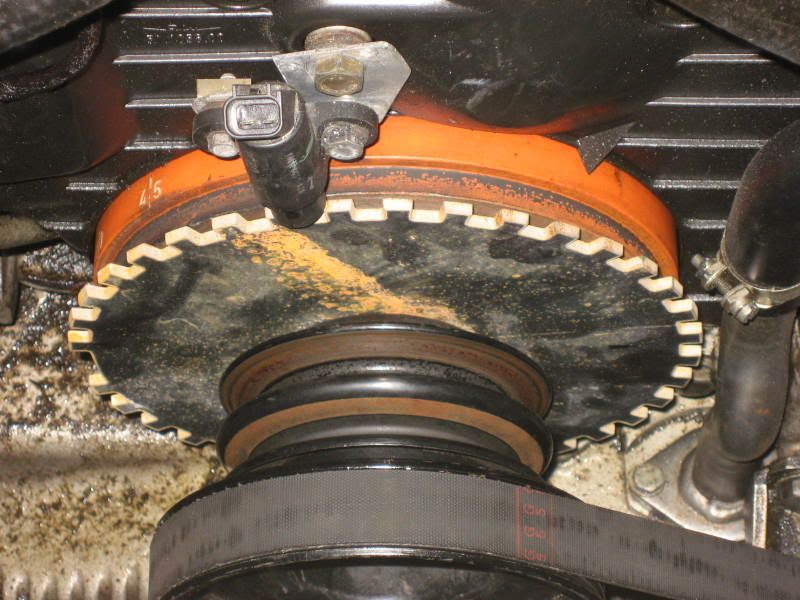
instead of replacing the AC pulley it would be easy to make a larger hole in the center so that the ring will slide up on outter pulley and butt up against the engine most V. And you can then weld this ring to the outter pulley instead of loosing the AC pulley.
instead of replacing the AC pulley it would be easy to make a larger hole in the center so that the ring will slide up on outter pulley and butt up against the engine most V. And you can then weld this ring to the outter pulley instead of loosing the AC pulley.
12-08-2008, 12:33 PM
#13
Addict
Lifetime Rennlist
Member
Lifetime Rennlist
Member
Here is a picture of the 36-1 toothed ring replacing the factory AC pulley
instead of replacing the AC pulley it would be easy to make a larger hole in the center so that the ring will slide up on outter pulley and butt up against the engine most V. And you can then weld this ring to the outter pulley instead of loosing the AC pulley.
instead of replacing the AC pulley it would be easy to make a larger hole in the center so that the ring will slide up on outter pulley and butt up against the engine most V. And you can then weld this ring to the outter pulley instead of loosing the AC pulley.
I love this kind of stuff! good ole DIY!
12-08-2008, 01:22 PM
#15
Nordschleife Master
Thread Starter
Hessank,
I am using a GM TPS, which mounts straight onto the TB with only a small piece of steel to be able to adapt it as the holes as they were not as far apart as the factory TPS switch.
I am using a GM TPS, which mounts straight onto the TB with only a small piece of steel to be able to adapt it as the holes as they were not as far apart as the factory TPS switch.