When you click on links to various merchants on this site and make a purchase, this can result in this site earning a commission. Affiliate programs and affiliations include, but are not limited to, the eBay Partner Network.
I'm trying to envision piston position in relationship to that flat area that got added into your combustion chambers. Before, during, and after overlap....seems like the welded area would be blocking anything that was done on the outside 1/4 of the valve pocket on the piston. Any relief out the side of the valve pocket would seem like it would be in a fairly useless area to affect airflow.
I been drawing cross sections (in my mind) and it seems like the piston is going to have to be pretty far in the hole, before that added welded wall isn't in the way of airflow to the outer part of the actual piston.....where most of any pocket porting is done.
There's no low-lift shrouding in those heads. It's hard to see it from the photos that don't have the best perspective, but the curtain area between the valve seat and the valve (computed using the detailed formula that takes into account the valve job) is the constraint up to a reasonably high lift (forgot the actual lift number). At higher lifts, the bore size comes into the equation, as well as the "shrouding" air flow from the other intake valve.
There are reasons why things are the way they are in those heads, I believe. The first important thing is that these heads aren't going to flow the intake charge straight to the exhaust at low lifts during overlap. They will also (likely) produce very efficient tumble in because the high-lift flow (which these heads have more than enough) is guided and diffused by the combustion chamber wall and the exhaust valve face. And, finally, the heads will likely burn very quickly because the combustion chamber is very compact and because there's enough squish area.
This mold-making photo hopefully shows better that there's no low-lift shrouding. Consider the valve angle when the valve opens. What may look like shrouding from some photos is in reality a diffuser. No wall whatsoever to the side would not be the optimal for the flow coefficient, a wall at the right distance (and angle) from the flow produces the highest flow coefficient.
You are correct that the circular dish pistons matched with these heads have very small valve reliefs and they aren't notched on the sides. But that's mostly because of the dish shape, with different type of piston these heads could also potentially benefit from notches on the piston in one quarter of the valve circumference. By the way, that quarter of the circumference isn't really impacted by the additional material in the heads.
These heads will likely end up on a normally aspirated engine at some future point, as they solve many issues that are more important to solve in a normally aspirated engine then in a turbo engine. Also, the cost of replicating those heads would be so high that they are likely one offs no matter how well they work. But in the process of trying them I'll hopefully learn something.
While I appreciate your theory, enthusiasm, and rationalizations, my actual real world work on 928 heads shows just the opposite helping these engines, in real world running engines.
Like the heads you pictured above from the Ford application, the further I unshroud the valves in the 928 head, the more the efficiency and output of these engines increases.
I'm now to the point where I'm significantly relieving the edge where the stock quench area is....and both power and efficiency continue to rise. My next set of heads will " carve" into this area much more....much like the Ford heads you pictured
I only need to point to Jim Corenman's 5.9 liter engine, equipped with these features, which makes virtually identical (if not more) torque and horsepower as prior 6.5 liter versions, with the same compression, and camshaft design. This result is completely a result of changes to the cylinder head.
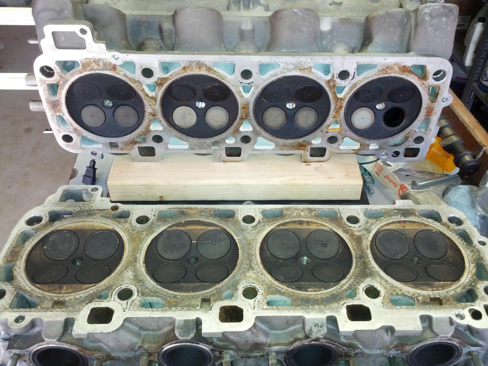
As you may or may not be aware, I'm also very involved with Big Block Chevy engines. I pulled out an early closed chamber head (from a closed chamber L88), a LS7 open chamber (big block) head, and two examples of state if the art "modified" open chamber design heads (high end aftermarket aluminum heads)....just for a point of reference. These heads also show that a continual shift towards unshrouding and opening up of the combustion chamber has greatly increased power output and engine efficiency. It would be silly, for someone trying to raise effiency, torque, or horsepower, to think aboit going backwards and using a closed chamber head, today.
While I personally believe your theory is unfounded and is a step backwards, I do wish you luck and will look forward to the results of your efforts!
It's interesting if your 5.9L engine makes more power and torque than your 6.5L engine with everything else the same. However, I suspect that not everything else is the same - why would it be. I also suspect that if you'd only increase the stroke on that 5.9L engine while holding everything else constant, power and torque would go up (but probably by less than the displacement increase). But that's just my guess. Was that my prediction that you referenced in your post? We seem to sometimes live in parallel universes regarding questions such as whether 39mm valve flows more in the flow bench on 100mm bore than a 37mm valve. Not every gap in opinions will be bridged, which is fine.
The big block Chevy, especially the large cube models, is so severely valve limited that any sort of change that gives more flow on the flow bench appears to (by published reports, no personal experience) increase power. I'm thinking that given how much flow one can get from the 928 4V heads, that's in most cases not at all similar situation to a big block Chevy.
For the 928 4V head, my thinking is that one should think about the valve flow in two different regimes. Flow during the overlap when both intake and exhaust are open, and flow during the intake cycle when only intake valves are open. In my opinion, the requiremts at those two different stages are completely different. In my opinion, unshouding on the squish pad side of the valve only really matters for the low-lift flow "overlap" regime when both intake and exhaust valves are open.
I'm not claiming that I'm always correct. Learning has happened and will hopefully continue to happen! However, what I think I've been pretty successful at is always being honest and never knowingly posting technical information that I know to be false. I also think that I've been reasonably successful in treating everyone's technical views on their merits and not letting personal animosities or posting histories to get in the way of technical discussions.
Originally Posted by GregBBRD
While I appreciate your theory, enthusiasm, and rationalizations, my actual real world work on these heads shows just the opposite reality.
Like the heads you pictured above from the Ford application, the further I unshroud the valves in the 928 head, the more the efficiency of these engines increases.
I'm now to the point where I'm relieving the edge where the stock quench area is....and both power and efficiency continue to rise.
I only need to point to Jim Corenman's 5.9 liter engine, equipped with these features, which makes virtually identical (if not more) torque and horsepower as prior 6.5 liter versions (which you predicted it would not.)
As you may or may not be aware, I'm also very involved with Big Block Chevy engines. I pulled out an early closed chamber head, an LS7 (big block) head, and two examples of state if the art "modified" open chamber design heads (high end aftermarket aluminum heads)....just for a point of reference. These heads also show that a continual shift towards unshrouding and opening up of the combustion chamber has greatly increased power output and engine efficiency. No one, trying to raise effiency, torque, or horsepower would go backwards and use a closed chamber head.
While I personally believe your theory is unfounded and is a step backwards, I do wish you luck and will look forward to the results of your efforts.
I'm now to the point where I'm significantly relieving the edge where the stock quench area is....and both power and efficiency continue to rise. My next set of heads will " carve" into this area much more....much like the Ford heads you pictured
...
These heads also show that a continual shift towards unshrouding and opening up of the combustion chamber has greatly increased power output and engine efficiency. It would be silly, for someone trying to raise effiency, torque, or horsepower, to think aboit going backwards and using a closed chamber head, today.
...might there be more S3-head experimentation in the future based on this premise?
the port area may be limiting but the chamber is wide-f***in open...
As you may or may not be aware, I'm also very involved with Big Block Chevy engines...
another random question on this...have you considered getting a few more of those "custom aluminum BBC block modified to fit 928 4v heads" like that san diego hotrod guy's? custom block means you can change engine mounting and bellhousing provisions to make it "bolt in".
It's interesting if your 5.9L engine makes more power and torque than your 6.5L engine with everything else the same. However, I suspect that not everything else is the same - why would it be. I also suspect that if you'd only increase the stroke on that 5.9L engine while holding everything else constant, power and torque would go up (but probably by less than the displacement increase). But that's just my guess. Was that my prediction that you referenced in your post? We seem to sometimes live in parallel universes regarding questions such as whether 39mm valve flows more in the flow bench on 100mm bore than a 37mm valve. Not every gap in opinions will be bridged, which is fine.
The big block Chevy, especially the large cube models, is so severely valve limited that any sort of change that gives more flow on the flow bench appears to (by published reports, no personal experience) increase power. I'm thinking that given how much flow one can get from the 928 4V heads, that's in most cases not at all similar situation to a big block Chevy.
For the 928 4V head, my thinking is that one should think about the valve flow in two different regimes. Flow during the overlap when both intake and exhaust are open, and flow during the intake cycle when only intake valves are open. In my opinion, the requiremts at those two different stages are completely different. In my opinion, unshouding on the squish pad side of the valve only really matters for the low-lift flow "overlap" regime when both intake and exhaust valves are open.
I'm not claiming that I'm always correct. Learning has happened and will hopefully continue to happen! However, what I think I've been pretty successful at is always being honest and never knowingly posting technical information that I know to be false. I also think that I've been reasonably successful in treating everyone's technical views on their merits and not letting personal animosities or posting histories to get in the way of technical discussions.
Over time, I've grown to appreciate how much time and effort you spend researching what you think and what you do. You are very studied.
I spend no time reading (outside of this Forum) what others are doing, have done, or have thought about doing. I simply do not have the hours to do this....I'm too busy doing my own thing.
I've never run an exhaust header, intake manifold, or any type of engine simulation....never. Actually, never plan on doing any of those things.
My methods are to design, fabricate, and test. See how it works, and do again, if necessary. Repeat as necessary until the desired results are obtained.
I build things out of my own head....my own creations based on my own experiences. My own ideas. No mentor, no other resources....just me.
This ends up meaning that I'm virtually opposite of you. I'm not "studied"....at all. I deal only in first hand reality....real world application and testing.
When I make a design change in some part of the 928 engine....it's a reaction to something I've seen that I don't like or find inadequate.
I was pretty well convinced that the limits I had reached on the larger stroker engines were not because of displacement, but because of other factors. Jim's 5.9 liter engine was an "experiment" to test my theory....plus Jim wanted to try something new and unique. We built him a virtual duplicate of one of my existing 6.5 liter engines....same camshaft design, same compression, everything the same....except the heads. I ran smaller valves (stock sizes), instead of larger intakes. I did some "new" combustion chamber work, and made a few other changes.
The 5.9 liter version made virtually the same horsepower. Torque was down a little bit at the lower/mid range...I think ~20 ft lbs.
As I've stated, the more I open up the shrouding of the 928 valves, the more efficient the engines get. More power per cubic inch. Cleaner combustion. Less ignition timing required. Everything pointing towards better cylinder filling and better flame proprogation.
When I saw the heads you have and my instant reaction was...."What the hell were these people thinking that did this?". Understand that from my own perspective of what I've been building and doing, this approach is completely contrary....180 degrees in the opposite direction.
However, I've got an open mind....might turn out to be the best thing, ever.
I guess, at some point in time, you might build an engine out of these heads. If that happens, the proof will be in the result.
In the meantime, I'm working with pure reality....not theory. The target I have (for the 5.9 liter variant that I'm currently working on) is to make over 500 horsepower and for it to be able to run at 7500 rpms all day long....through a single butterfly. (Note that this is ~50hp more than Jim's engine, with a "stock" intake manifold.)
It discusses a number of tradeoffs that have come up in this thread as well.
I have read this article too, it's amazing how engines can be compared using modern simulation techniques.
No wonder why 911 folks have installed two spark plugs to old engines. http://rennsportsystems.com/letstalk...twin-ignition/
The Honda S2000 does have great tumble intensity, here is more information from S2000 engine development. Document also talks Nissan RB20DE features. http://www.s2000.org/articles/f20carticle.pdf
It's an interesting question how much deshrouding is necessary for our valves.
My opinion is that it's important for the valves to flow througout the 360-degree perimeter during the overlap. By this logic, we want to make sure that the intake valve is fully deshrouded up to the intake lift at the EVC and the exhaust valve is fully deshrouded up the exhaust lift at IVO.
Suppose that you'll have high-overlap cams. For a single throttle plenum manifold 928, that by my guess means that the intake valve is open 4mm or less by the time exhaust valve closes. For stock S4 cams it's less, and I doubt that anyone is running more than that with a single-throttle plenum manifold.
Below, I did a spreadsheet with values that are in the ballpark for the stock S4 head with stock 37mm intake valves:
Lift L mm 1.00 1.50 2.00 2.50 3.00 3.50 4.00
Valve seat angle angle deg 45 45 45 45 45 45 45
Valve seat angle angle rad 0.79 0.79 0.79 0.79 0.79 0.79 0.79
Valve seat inside diameter dis mm 35.16 35.16 35.16 35.16 35.16 35.16 35.16
Valve seat outside diameter dos mm 37.00 37.00 37.00 37.00 37.00 37.00 37.00
Valve stem diameter dvs mm 6.50 6.50 6.50 6.50 6.50 6.50 6.50
Valve throat diameter dth mm 31.00 31.00 31.00 31.00 31.00 31.00 31.00
Curtain area shift point Llim mm 1.84 1.84 1.84 1.84 1.84 1.84 1.84
Throat area Amax mm^2 721.6 721.6 721.6 721.6 721.6 721.6 721.6
Constraining flow area flow area mm^2 79.2 119.7 160.8 207.3 257.8 310.5 364.4
Deshrouding circle diameter drf mm 38.34 39.00 39.67 40.41 41.20 42.00 42.81
Radial deshrouding clearance clearance mm 0.67 1.00 1.34 1.70 2.10 2.50 2.91
Ratio of lift to radial deshrouding ratio 0.67 0.67 0.67 0.68 0.70 0.71 0.73
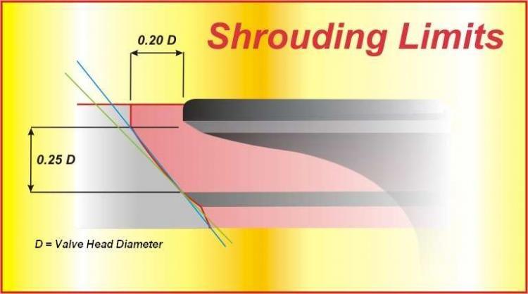
Pick the column that corresponds to your intake valve lift at the exhaust valve closing point. Or pick the realistic worst case, say 4mm. The spreadsheet does the math how much radial clearance parallel to the intake valve face one would need to not constrain the flow are at any point.
For example, if you think your intake valve is 3.5mm open when the exhaust valve closes, then you want to deshroud the valve by 2.5mm around the valve seat OD. The deshrouding should be slightly convex space that starts from the valve seat OD in the seat insert and finishes at the plane that is parallel to the valve seat OD in the valve when valve is at 3.5mm lift.
If one wants to do something a little simpler instead of digging the convex "ditch", then one can conservatively draw a 38 degree cone from the valve seat OD at the valve seat insert and remove the material inside this cone. This is what those David Vizard books suggest. He's using the lift to deshrouding clerance ratio of 20/25 = 0.8, which I think is conservative. I don't think it's the mathematically minimum shrouding condition, but it's really close so probably very good practical rule:
After the EVC, in my opinion, it's no longer that important that the valve flows throughout the entire valve perimeter. Most of the flow is going to go over the long side radius, and that's arguably a good thing as that flow is well supported by the exhaust valve face and will result in efficient tumble. One just needs to get enough flow and good enough coefficient of discharge by the maximum piston speed crank angle which is about 75 degrees ATDC.
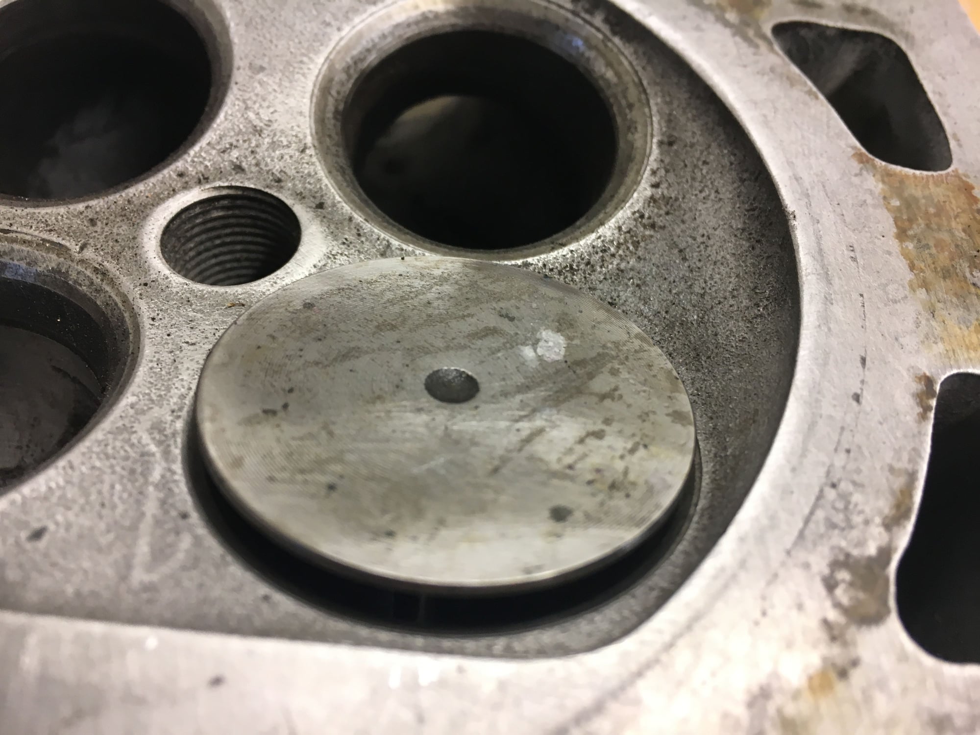
For reference, this is a stock S4 head with the intake valve 3.5mm open. As you can see, it's about as unshrouded as it can be on 100mm bore. Running a 39mm valve on 100mm bore would be a lot more challenging project from low-lift flow shrouding perspective without moving the intake valves closer to each other (no small project).
Make a bunch more sense with the pictures. Seems like a bigger bore would allow some uselful de-shrouding while adding some power - sort of a synergistic effect.
...no "quench shrouding" to speak of on the S3, compare that to the S4/944S...
I wonder if the coolant jacket would permit machining away entirely the S4 quench pads to mimic the S3 chamber shape/size.
you'd have to change pistons to get your CR back though.
It's an interesting question how much deshrouding is necessary for our valves.
My opinion is that it's important for the valves to flow througout the 360-degree perimeter during the overlap. By this logic, we want to make sure that the intake valve is fully deshrouded up to the intake lift at the EVC and the exhaust valve is fully deshrouded up the exhaust lift at IVO.
Suppose that you'll have high-overlap cams. For a single throttle plenum manifold 928, that by my guess means that the intake valve is open 4mm or less by the time exhaust valve closes. For stock S4 cams it's less, and I doubt that anyone is running more than that with a single-throttle plenum manifold.
Below, I did a spreadsheet with values that are in the ballpark for the stock S4 head with stock 37mm intake valves:
Lift L mm 1.00 1.50 2.00 2.50 3.00 3.50 4.00
Valve seat angle angle deg 45 45 45 45 45 45 45
Valve seat angle angle rad 0.79 0.79 0.79 0.79 0.79 0.79 0.79
Valve seat inside diameter dis mm 35.16 35.16 35.16 35.16 35.16 35.16 35.16
Valve seat outside diameter dos mm 37.00 37.00 37.00 37.00 37.00 37.00 37.00
Valve stem diameter dvs mm 6.50 6.50 6.50 6.50 6.50 6.50 6.50
Valve throat diameter dth mm 31.00 31.00 31.00 31.00 31.00 31.00 31.00
Curtain area shift point Llim mm 1.84 1.84 1.84 1.84 1.84 1.84 1.84
Throat area Amax mm^2 721.6 721.6 721.6 721.6 721.6 721.6 721.6
Constraining flow area flow area mm^2 79.2 119.7 160.8 207.3 257.8 310.5 364.4
Deshrouding circle diameter drf mm 38.34 39.00 39.67 40.41 41.20 42.00 42.81
Radial deshrouding clearance clearance mm 0.67 1.00 1.34 1.70 2.10 2.50 2.91
Ratio of lift to radial deshrouding ratio 0.67 0.67 0.67 0.68 0.70 0.71 0.73
Pick the column that corresponds to your intake valve lift at the exhaust valve closing point. Or pick the realistic worst case, say 4mm. The spreadsheet does the math how much radial clearance parallel to the intake valve face one would need to not constrain the flow are at any point.
For example, if you think your intake valve is 3.5mm open when the exhaust valve closes, then you want to deshroud the valve by 2.5mm around the valve seat OD. The deshrouding should be slightly convex space that starts from the valve seat OD in the seat insert and finishes at the plane that is parallel to the valve seat OD in the valve when valve is at 3.5mm lift.
If one wants to do something a little simpler instead of digging the convex "ditch", then one can conservatively draw a 38 degree cone from the valve seat OD at the valve seat insert and remove the material inside this cone. This is what those David Vizard books suggest. He's using the lift to deshrouding clerance ratio of 20/25 = 0.8, which I think is conservative. I don't think it's the mathematically minimum shrouding condition, but it's really close so probably very good practical rule:
After the EVC, in my opinion, it's no longer that important that the valve flows throughout the entire valve perimeter. Most of the flow is going to go over the long side radius, and that's arguably a good thing as that flow is well supported by the exhaust valve face and will result in efficient tumble. One just needs to get enough flow and good enough coefficient of discharge by the maximum piston speed crank angle which is about 75 degrees ATDC.
For reference, this is a stock S4 head with the intake valve 3.5mm open. As you can see, it's about as unshrouded as it can be on 100mm bore. Running a 39mm valve on 100mm bore would be a lot more challenging project from low-lift flow shrouding perspective without moving the intake valves closer to each other (no small project).
Just opinions, and everyone's got one.
"Opinions" are something that only stand until reality takes their place....
The information you find on the Internet doesn't trump the reality I experience, while actually building these engines and running them.
Are you honestly suggesting that I quit unshrouding the valves on the 928 head and go back to engines that make less power, are less efficient, and require more ignition timing?
How can you show that picture of EMC winning Ford modular engine head (post 380).....completely unshrouded all the way to the cylinder bore....while arguing that the most shrouded 928 head ever dreamed up going to be fantastic?
Get off the Internet. Build it. Show us.
When you can make 500+ horsepower from a 5.9 liter naturally aspirated street 928 engine, I'll use your ideas....
When Racelab in norway did my 951 head, he made the ports smaaler, and more efficient inn how he air passed the valve, making it flow a lot more, especialy on low lift. ( from 200 cfm to 268cfm )
"Opinions" are something that only stand until reality takes their place....
The information you find on the Internet doesn't trump the reality I experience, while actually building these engines and running them.
Are you honestly suggesting that I quit unshrouding the valves on the 928 head and go back to engines that make less power, are less efficient, and require more ignition timing?
How can you show that picture of EMC winning Ford modular engine head (post 380).....completely unshrouded all the way to the cylinder bore....while arguing that the most shrouded 928 head ever dreamed up going to be fantastic?
Get off the Internet. Build it. Show us.
When you can make 500+ horsepower from a 5.9 liter naturally aspirated street 928 engine, I'll use your ideas....
Thanks for the motivation, I do need a nudge to see how those heads would run on a normally aspirated engine. The current iteration of the turbo project is getting closer to the goal line so I'll have to figure out something to do after the summer. It will be interesting to see if reading books helps or hurts in a project like that!
Is that 500 hp target with the stock S4 intake manifold or with something else?
Another thing that kind of puzzles me is why do those welded heads strike so much fear in your heart? They are just heads that someone welded and ported. It's like Carl posting something here, a total "trigger word" for you. �ke asked me a question about them, I speculated about the answer, and suddenly the laws of geometry are suspended...
I'm taking your probably facetious question what I think you should do at the face value. From what I can gather without seeing your combustion chamber, you are running a 104mm or so bore, you are extending the combustion chamber towards the bore wall around the valves, you call it "unshrouding", and you think it works. Sounds great, keep doing it! I am not suggesting you change anything you're doing. I'm just passing time trying to figure out why what works, works. I am scratching my head about how it could be valve shrouding on the squish pad side of a four-valve head, given the valve angle and geometry. I guess I'll have to think about it harder.
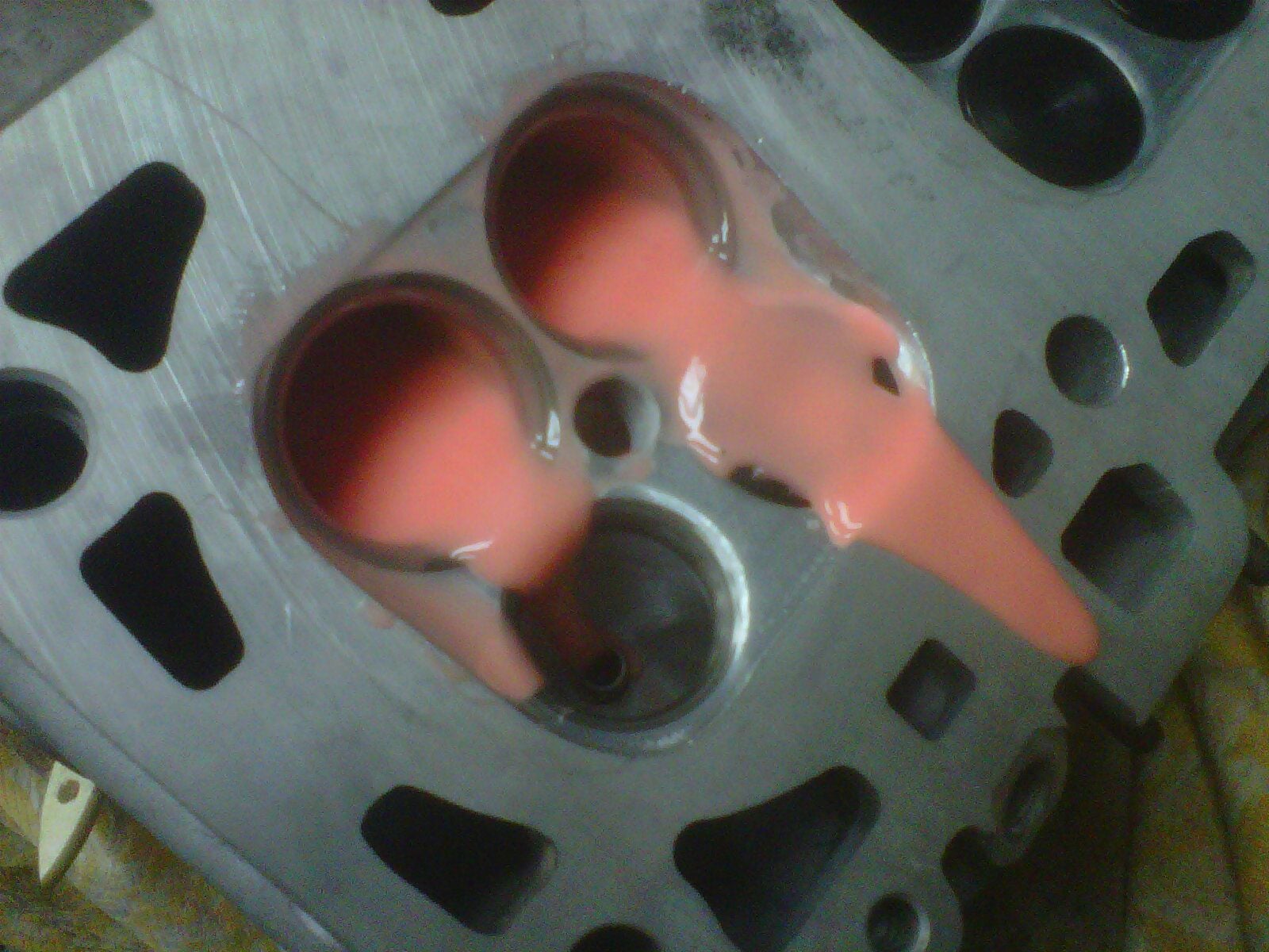
By the way, for what it's worth, I'm pretty sure that the Ford EMC engine had both valves sunk deeper and most likely also a little bit of material added, adding to what you call shrouding. They started as Ford GT castings. Here's what they look like before modifications:

 04-09-2017, 02:57 PM