When you click on links to various merchants on this site and make a purchase, this can result in this site earning a commission. Affiliate programs and affiliations include, but are not limited to, the eBay Partner Network.
The Pipemax is giving me CSA of little more than 2 sq in. BTW. what are the stroke and bore for 7L engine, would like to check this more detailed?
The CSA from my calculation was smallest recommended, highest was 2,5 sq in. However, those are very rough as don't know all the details of engine.
Basically the exh. port area should taper up towards port exit being between 105 - 110% of the valve.
Found the following once from speedtalk when thinking of exh. port shape and size. The writer is well known engine builder, no reason to disagree at least from my side.
This doesn't apply to your 7L engine, but thinking of shape would be benefical. The valve size in following example was 40mm, IIRC.
*****************************
I would make the throat 90% and the turn 85% of valve diameter. That is 1.578 sq.in. throat and 1.407 sq.in. turn above the SSR.
As soon as you are 10mm past the SSR you can open up the port but don't taper it more than 7 degrees included angle.
Whatever you do don't make the SSR larger than the throat in a sharp turning port. If you have a 90% throat don't make the turn bigger than 85% of the valves diameter.
You can widen the port but do not raise the roof or lower the floor.
****************************
The bore is 108mm, stroke 95.25mm, dual valves 42/36.
�ke
The 330fps is the choke point, people prefer to use 300+fps values, though. Will send you separate mail about used inputs and received other outputs.
I adjusted the rpm and VE just to get around 800hp max.
Required Intake Flow between 346,3 CFM and 367,1 CFM at 28 Inches
Required Exhaust Flow between 275,4 CFM and 296,6 CFM at 28 Inches
00 RPM/Sec Dyno Test Lowest Low Average Best
Peak HorsePower 745,5 776,2 791,5 806,9
Peak Torque Lbs-Ft 551,2 573,9 585,2 596,5
--- Cross-Sectional Areas at various Exhaust Port Velocities (@ 28 in.) ---
160 FPS at Exhaust Valve Curtain Area= 4,283 sq.in. at ,481 Lift
218 FPS at Exhaust Valve OD Area and at Convergence Lift = ,354
269 FPS 90% PerCent Rule Seat-Throat Velocity CSA= 2,555 sq.in. at 7800 RPM
435 FPS Velocity CSA= 1,578 sq.in. at 7800 RPM Sonic Choke at Throat Area
350 FPS Velocity CSA= 1,960 sq.in. at 7800 RPM Port Sonic-Choke with HP Loss
330 FPS Velocity CSA= 2,080 sq.in. at 7800 RPM Port Sonic-Choke with HP Loss
311 FPS Velocity CSA= 2,207 sq.in. at 7800 RPM Smallest Useable Port CSA
300 FPS Velocity CSA= 2,288 sq.in. at 7800 RPM Recommended Smallest Port CSA
285 FPS Velocity CSA= 2,409 sq.in. at 7800 RPM Recommended Smallest Port CSA
250 FPS Velocity CSA= 2,746 sq.in. at 7800 RPM Recommended Port CSA
240 FPS Velocity CSA= 2,860 sq.in. at 7800 RPM Recommended Port CSA
225 FPS Velocity CSA= 3,051 sq.in. at 7800 RPM Largest Exhaust Port Exit CSA
210 FPS Velocity CSA= 3,269 sq.in. at 7800 RPM Largest Exhaust Port Exit CSA
190 FPS Velocity CSA= 3,613 sq.in. at 7800 RPM Torque Loss + Reversion
180 FPS Velocity CSA= 3,814 sq.in. at 7800 RPM Torque Loss + Reversion
I recommend everyone reading this spending a little bit of time with a pencil, paper, ruler, and compass thinking about whether it's the maximum lobe lift of the maximum velocity of the lobe that causes the lobe to go off the lifter.
IMO, it is maximum love lift, not velocity.
Carl, I do not understand what you mean by "the lobe walked on to the cam follower". Do you mean the lobe was riding on the edge of the follower?
I'm swamped with shop work right now and I have not been able to hunt through all my photo folders. I know I have the pics I want to show you that show you what I am trying to describe, just haven't found them yet. I will look again.
Ok, but since people will be reading this down the road, we can't leave it uncertain here that it's the lobe profile velocity (change in lift per change in degrees) or, in other words, how fast the cam opens the valve that determines whether the lobe goes out the lifter edge. It is without a question _not_ the maximum lift that determines whether the lobe goes out of the lifter (for any sort of practical cam profiles with which the engine can run). I am not Alice and this is not Wonderland, right? Or am I and is it?
Found 'em! These photos show what I was trying to describe, that the cam lobe was long enough that only the center of the lobe was actually on the cam follower, and as it turned, the rest of the lobe walked on to it.
We got some funny wear patterns on the cam lobes after a full season of this, but it didn't bother them much. We figured we were at the absolute limit of static lobe height (we had already moved our base circle too) unless we went to a larger diameter cam follower like you are describing.
I think that once you think thru the geometry, the issue _is not_ whether the nose of the cam is outside of the lifter in horizontal dimensions when the nose is far from touching the lifter. The issue _is_ whether the contact point of the cam lobe and the lifter moves to the edge. The contact point starts from the center when the valve is closed and then, as the valve accelerates, the contact point moves closer to the lifter edge. It should not go over the edge.
The nose itself can be over the edge when the nose is not the contact point, and that's not relevant. The nose just has to come in (in the horizontal dimension) before it touches the lifter. It's fine if the cam lobe "walks onto the lifter" from outside as long as the point of the lobe that actually touches the lifter is always clearly fully on the lifter and not on the edge.
What this translates into is that if the cam has a longer duration, you can have a higher max lift, and you'll have no problem. It's only when you try to have a relatively short duration AND a high max lift when the lobe digs into the lifter edge.
There are a lot more subtle issues in cam design than this that can cause the camshaft to be unreliable, for example, on which side the oil film wedge is and when does it cross over and how thick the oil film is at that point, etc. That's why cam design is basically a full time job.
The nose itself can be over the edge when the nose is not the contact point, and that's not relevant. The nose just has to come in (in the horizontal dimension) before it touches the lifter. It's fine if the cam lobe "walks onto the lifter" from outside as long as the point of the lobe that actually touches the lifter is always clearly fully on the lifter and not on the edge.
I agree, but I will add I hated to see such a concentration of load on such a small point of the lobe (albeit the center of the lobe and the strongest part) until the cam turned further and the load could be distributed over the entire width. It's asking a lot from your oil wedge and your metals, I thought.
That said, I ran it like this for a full race season without detriment. I only mentioned it when I saw Strosek's post about cutting the head to allow swing clearance for even larger lobes.
Yes, your point is absolutely correct. And yes, Carl is missing it.
More "roundness" on the ramps of the cam would keep the cam in contact with the lifter and allow the top of the lobe to "merge" into the lifter without it hitting the edge of the lifter. Simple geometry.
If you think about it a little bit more, you could do this without really affecting the overall duration. You could still have the same opening and closing events, but with a rounder lobe shape. My initial thought is that lifter acceleration might go up, but in thinking more about it, it might actually go down...since the lift could be spread out more thoughout the entire lift phase, possibly making the acceleration rate lower. I guess I'd have to draw this....or ask someone a bunch smarter (like a cam designer.)
It's also interesting to note with a lobe shape that is "rounder", the amount the valve was open at any point on the ramp would increase....which would obviously allow more air to enter on the ramps of the cam.
It is interesting that overhead camshafts seem to have very steep ramps with very "pointy" lobes. American push rod engines have rounder lobes and are much less "pointy".....even for very radical flat tappet cams. I've always thought this was because most overhead camshaft engines have hemi-shaped combustion chambers, with the intake and exhaust valves in the same vertical plane and that making the lobes "rounder" would make valve to valve contact an issue.
No, not really. At least I don't think so. But maybe I'm Alice.
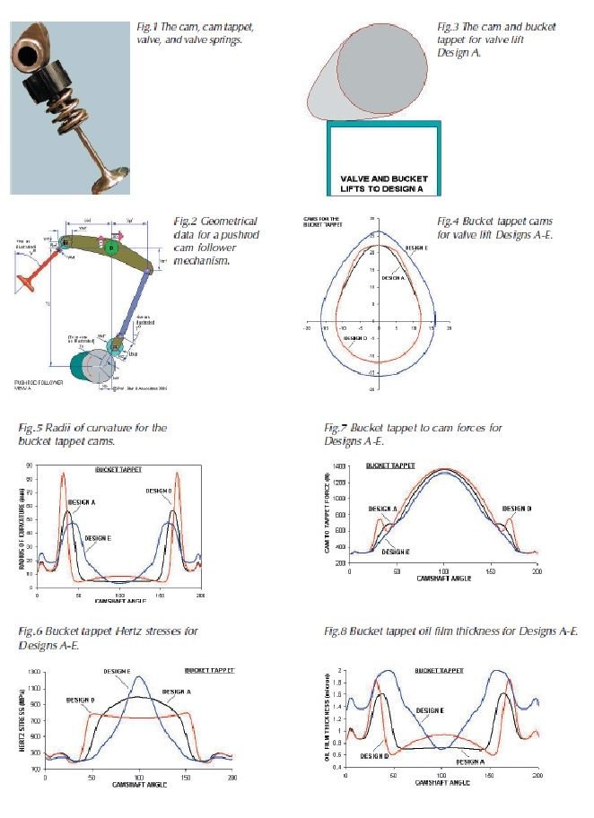
If one is really interested in how the cams are designed and why they look the way they look, in my opinion a good place to start is here. There's specifically a comparison of a pointy-nosed cam and round-nosed cam on a flat bucket lifter:
Here are some figures from that article that graphically explain the differences between a pointy-nosed and round-nosed cam on a flat bucket lifter:
That article reads to me as a good introduction to camshafts for someone who's read a couple of general mechanical engineering textbooks. It explains, for example, why you can't just be cutting down the base circle smaller.
If one wants to actually understand what the mathematical constraints are, one could read the following book and program the associated equations to Matlab, Octave, or even Excel:
J.J. Williams. Introduction to Analytical Methods for Internal Combustion Engine Cam Mechanisms. Springer, 2013.
In any case, this is all just for general education and entertainment, at least for me. For me, it has reinforced by belief that two separate people can (and probably should) be deciding (a) what kind of valve events and approximate valve lift curve the engine wants and (b) how to actually make a reliable camshaft system that approximately delivers what the first person thinks the engine wants. Opinions on this may vary as well.
Originally Posted by GregBBRD
More "roundness" on the ramps of the cam would keep the cam in contact with the lifter and allow the top of the lobe to "merge" into the lifter without it hitting the edge of the lifter. Simple geometry.
If you think about it a little bit more, you could do this without really affecting the overall duration. You could still have the same opening and closing events, but with a rounder lobe shape. My initial thought is that lifter acceleration might go up, but in thinking more about it, it might actually go down...since the lift could be spread out more thoughout the entire lift phase, possibly making the acceleration rate lower. I guess I'd have to draw this....or ask someone a bunch smarter (like a cam designer.)
It's also interesting to note with a lobe shape that is "rounder", the amount the valve was open at any point on the ramp would increase....which would obviously allow more air to enter on the ramps of the cam.
It is interesting that overhead camshafts seem to have very steep ramps with very "pointy" lobes. American push rod engines have rounder lobes and are much less "pointy".....even for very radical flat tappet cams. I've always thought this was because most overhead camshaft engines have hemi-shaped combustion chambers, with the intake and exhaust valves in the same vertical plane and that making the lobes "rounder" would make valve to valve contact an issue.
Found 'em! These photos show what I was trying to describe, that the cam lobe was long enough that only the center of the lobe was actually on the cam follower, and as it turned, the rest of the lobe walked on to it.
We got some funny wear patterns on the cam lobes after a full season of this, but it didn't bother them much. We figured we were at the absolute limit of static lobe height (we had already moved our base circle too) unless we went to a larger diameter cam follower like you are describing.
Hope this helps.
From the pictures I can see this particular cam profile used by Carl is what we call an aggressive profile being hard on the valve train. An aggressive cam profiles means short duration with fairly high lift and high lift velocity, it is good for engine performance but need more spring pressure increasing the wear. High lift velocity cam profiles call for large diameter lifters. In order to overcome the problem with very large size lifters some engine manufacturers (Porsche, BMW) has moved to radiused lifters which allow high lift velocity with a smaller lifter size. Slate Blue is going that way for his build. https://rennlist.com/forums/928-foru...er-thread.html (post #10).
The lift rate is expressed in thousands of an inch per degree of rotation (TPD). In order to calculate the minimum safe flat lifter diameter you need to find out the maximum velocity point of the cam profile. The maximum velocity of a cam occurs when the cam is contacting the lifter nearest its edge. The cam grinder can provide you with the needed figure or you can measure (fingerprint) the cam yourself.
For example the profile (grind) #274 (see post #330), according to the specs I have from the cam manufacturer, has a maximum lift velocity of 12.044 TPD. In order to find out the minimum safe lifter diameter, divide TPD with 8.5 which is a constant.
The result will be a minimum safe flat tappet diameter of 1.4169" or 35.99mm. The cam profile #274 do need to be run on an oversize lifter. The stock lifter being 35mm.
�ke
Correct. Merely sharing ("warts and all" as they say) an experience I had that I hope would be helpful or instructive.
That doesn't mean I am "missing it", Greg. Curb your enthusiasm that I might have erred, OK? There is no correlation between this cam grind three years ago that was less than optimal and "Carl doesn't understand cam grinds" as you seem eager to infer.
If we are only allowed to share what works without criticism, you cut your self off from a very large pool of trial and error experience that is also instructive.
OMG....here we go again.
All I said was that you were not understanding Tuomo's point and was confirming that the point he was making was correct. His frustration about you not "getting it" after 3 attempts was evident in his post #340. His exasperation was for you....
What you do or do not know about these engines concerns me in absolutely no way, shape, or form.


 03-09-2017, 10:07 AM