
Port and Polish by Comiittee thread (Cool pics throughout)

 02-24-2014, 08:30 AM
#197
Ports can get probed so that they can be replicated on a CNC, I suspect if search Rottler who make machines that specialise in this field you may find youtube videos that so how it is done. Of course the first thing you need is a port that is worth replicating. It also has to be accurately sized to the application, I'm sure you know all that anyway.
http://www.aussiev8.com.au/holden-v8...roject-18.html
In the above link you can see some mapping that gets done to improve ports. The porter doing the work is who is charged with getting my heads to hopefully flow 400 cfm. I am sure he will give it a good shot.
You can see some of his other work here, bare in mind these are old cast iron heads, some from engines 40, 50 years old, not exactly cheap though but would you expect it to be? It's not done on a CNC, he has a good eye and steady hand and some excellent equipment including a 60" flow bench.
http://www.horsepowerengineering.com...0V6%20HEAD.jpg
http://www.horsepowerengineering.com.au/holden.htm
I think I am really lucky to have Peter take on this project and he is a perfectionist and he has an excellent record for accurately predicting the power his heads will make.
http://www.aussiev8.com.au/holden-v8...roject-18.html
In the above link you can see some mapping that gets done to improve ports. The porter doing the work is who is charged with getting my heads to hopefully flow 400 cfm. I am sure he will give it a good shot.
You can see some of his other work here, bare in mind these are old cast iron heads, some from engines 40, 50 years old, not exactly cheap though but would you expect it to be? It's not done on a CNC, he has a good eye and steady hand
and some excellent equipment including a 60" flow bench. http://www.horsepowerengineering.com...0V6%20HEAD.jpg
http://www.horsepowerengineering.com.au/holden.htm
I think I am really lucky to have Peter take on this project and he is a perfectionist and he has an excellent record for accurately predicting the power his heads will make.
 02-24-2014, 04:00 PM
#199
Rennlist Member
Thread Starter

Ports can get probed so that they can be replicated on a CNC, I suspect if search Rottler who make machines that specialise in this field you may find youtube videos that so how it is done. Of course the first thing you need is a port that is worth replicating. It also has to be accurately sized to the application, I'm sure you know all that anyway.
http://www.aussiev8.com.au/holden-v8...roject-18.html
In the above link you can see some mapping that gets done to improve ports. The porter doing the work is who is charged with getting my heads to hopefully flow 400 cfm. I am sure he will give it a good shot.
You can see some of his other work here, bare in mind these are old cast iron heads, some from engines 40, 50 years old, not exactly cheap though but would you expect it to be? It's not done on a CNC, he has a good eye and steady hand and some excellent equipment including a 60" flow bench.
http://www.horsepowerengineering.com...0V6%20HEAD.jpg
http://www.horsepowerengineering.com.au/holden.htm
I think I am really lucky to have Peter take on this project and he is a perfectionist and he has an excellent record for accurately predicting the power his heads will make.
http://www.aussiev8.com.au/holden-v8...roject-18.html
In the above link you can see some mapping that gets done to improve ports. The porter doing the work is who is charged with getting my heads to hopefully flow 400 cfm. I am sure he will give it a good shot.
You can see some of his other work here, bare in mind these are old cast iron heads, some from engines 40, 50 years old, not exactly cheap though but would you expect it to be? It's not done on a CNC, he has a good eye and steady hand
and some excellent equipment including a 60" flow bench. http://www.horsepowerengineering.com...0V6%20HEAD.jpg
http://www.horsepowerengineering.com.au/holden.htm
I think I am really lucky to have Peter take on this project and he is a perfectionist and he has an excellent record for accurately predicting the power his heads will make.
02-24-2014, 11:20 PM
#200
Rennlist Member
Thread Starter
Some new port pictures to discuss:
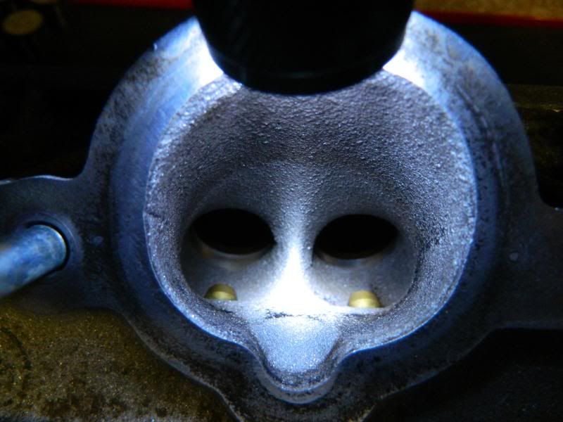
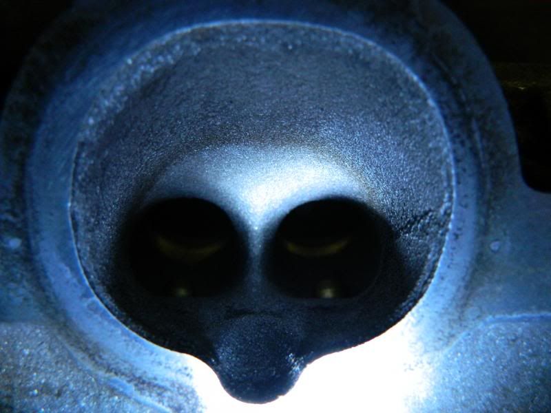
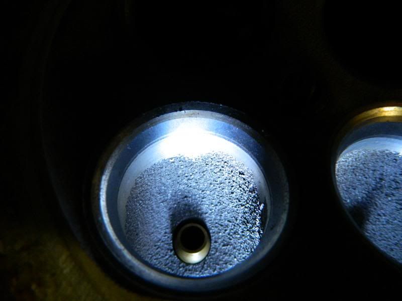
Exhaust
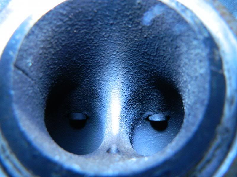
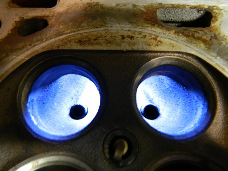


Exhaust

 02-25-2014, 09:16 PM
#201
Rennlist Member
Thread Starter
<<crickets...>
02-25-2014, 10:50 PM
#202
Three Wheelin'
Join Date: Aug 2003
Location: DFW
Posts: 1,641
Likes: 0
Received 0 Likes
on
0 Posts
My day job involves messing around with Coordinate Measuring Machines of various types. Besides measuring, they are very useful for reverse engineering complex shapes into a digital CAD file that can be used to program a CNC to replicate.
For freeform curvatures that don't require serious precision (say 0.005" or half the thickness of an average human hair) and don't have deep hidden pockets, the portable arm type machine equipped with a laser scanner is a good and fast method.
But to reach into deep pockets we're going to move to a "real" CMM, a 3 axis bridge machine with a long-stylus contact scanning probe mounted on a 4th & 5th axis head. We'll also get precision down to 0.0005" or better, but take all day messing around to get it perfect.
But raw data acquisition is only 1/3rd of the battle. Step 2 is massaging, filtering, smoothing, and solidifying the raw data with a dedicated reverse engineering software. This is required for Step 3... programming the CNC which has 10,000 things to consider.
Anybody interested, post here. I can't get PMs.
02-25-2014, 11:05 PM
#203
Rennlist Member
Thread Starter
The port shape needs to be mapped. I assume the map and 3D image data would have to contain the combustion chamber as well.
02-26-2014, 12:01 AM
#204
Three Wheelin'
Join Date: Aug 2003
Location: DFW
Posts: 1,641
Likes: 0
Received 0 Likes
on
0 Posts
Question: is this for replication or for flow simulation?
Replication would be difficult, lots of machine shop involvement, but have brilliant results. I have always wondered how in the world engine builders hand-grind identical port shapes into heads, I would look to CNC as an optimal method.
Flow simulation would require a software built for OHV piston engine simulations. Does your friend have access to one?
02-26-2014, 11:03 AM
#205
Rennlist Member
Thread Starter
Just the flow simulation for testing port shapes.
02-27-2014, 12:58 AM
#206
Nordschleife Master
I was thinking port shape in one head should be good in another similar motor, but now I am thinking combustion chamber shape might be a big factor or is it just flow through the port?
02-27-2014, 01:08 AM
#207
Rennlist Member
Thread Starter
From what I read it is logically part of the system. Where the fuel enters the chamber from the port flow. Where the ignition point is. The edges of the chamber in relation to the valves.
02-27-2014, 01:09 AM
#208
Rennlist Member
Thread Starter
Not a problem. Probably use the sparkplug hole as a starter reference point and the valve seats for alignment anyway, might as well map the chamber too.
Question: is this for replication or for flow simulation?
Replication would be difficult, lots of machine shop involvement, but have brilliant results. I have always wondered how in the world engine builders hand-grind identical port shapes into heads, I would look to CNC as an optimal method.
Flow simulation would require a software built for OHV piston engine simulations. Does your friend have access to one?
03-13-2014, 12:11 AM
#209
Rennlist Member
Thread Starter
On the short wall, you need to be very careful not to lower the floor and reduce the radius of the turn to the seat. However, this radius needs to be as consistant as you can make it. If the air "breaks" off of this wall, at higher velocities, it simply crashes into the air that is trying to go down the center of the port and then slams into the long wall. This kills the airflow numbers. You can hear this happen on a flow bench...you don't even need to look at the flow meters to know that things just turned to crap. You will want to remove and blend the cut from the installation of the valve seats into the floor. You will need to gently cut this back and blend, all the time, trying to improve and make the radius consistant. Lowering the floor and making the radius tighter will help flow, right up to the point where it can't make the bend, so unless you are willing to guess at this, I'd just think a nice radius would do you well.
This is the post I was looking for. This will be the extent of the work I will do on this set of heads for the intake.
I will also try to find any info on what to do about the exhaust. It has some strange casting shapes.
03-18-2014, 04:52 AM
#210
Instructor
Join Date: Oct 2005
Location: Finland
Posts: 137
Likes: 0
Received 0 Likes
on
0 Posts
To my understanding the following 4V port is close to perfect what comes to current knowledge or porting. The port floor has raised by TIG welding to enlarge the SSR.
Some of the material has been taken away from roof to straighten the port, this will work together with lifted port floor. The wall areas, where injector is sparaying are rough to keep good fuel atomization.
The smallest CSA can be clearly seen, it's just before the valve guide. The CSA is made to match desired flow and port velocity .Well known speedtalk secret is to roughen the throat area just before seat,
again perhaps for fuel atomization rather than flow. The implementation is similar as my 4V port, but we used epoxy to fille the floor.
Note; this is just an example and doen't mean you should go that far with your heads, but roughening walls and throat area really works.
About 928 4V exhaust port, my port has the SSR enlarged and port cleaned from extra roughness, nothing else. The size may become bottleneck if going very high hp numbers, I haven't measured it though.
About the company extreme tuners, they have bad reputation as they have advertised others products as their own and some other illegal. However, I like to see their facebook page, lot's of high tech EVO stuff and others.
Last edited by simos; 03-18-2014 at 08:56 AM.