
Port and Polish by Comiittee thread (Cool pics throughout)
 01-16-2015, 09:18 AM
#226
Nordschleife Master
Ake --
Fascinating. Thanks for sharing this info with everyone.
Some observations below, many based on our previous email conversations. This is my recollection of what the conclusions were, posted here for others to discuss. Please correct me if I recalled something wrong below:
- The stock port has a very high efficiency at low to mid lifts to start with.
- Camshafts and heads work together. One needs to have some idea of what cams will be used when porting a head. Conversely, one needs to have some idea of what head will be used when picking camshafts. Porting these heads will involve tradeoffs that depend on cams, mainly the maximum lift.
- Modifying the 928 intake valves, either stock 37mm or larger 968 39mm valves, to a more nail head shape will pick up flow at low and mid lifts. There's virtually no configuration where Ake's valve modifications don't help.
- It is virtually impossible to install 39mm valves to the 928 S4 heads while keeping the throat to valve diameter constant and not increase the high lift flow on any relevant bore size. This doesn't mean 39mm valve will always make more power, but it will virtually always flow more at high lifts in a flow bench.
- Five angle valve job picks up meaningful flow over the stock valve job. Where it picks up the most flow depends on the throat to valve diameter, the cut widths, and the cut angles. This is true for both large valves as well as stock 37mm valves.
- The stock head has about 83% throat to valve diameter ratio. This is very low. High performance heads that use high lift cams usually have ratios such as 90%. Does this mean that the stock design is erroneous? No, not necessarily. The low throat to valve diameter ratio will promote low lift and mid lift flow, but give up high lift flow. If the cams have no lift, like the S4 cams, one doesn't benefit from the high lift flow. Still, 83% is very low and one will do better with larger ratios. Where the ratio should be in the 86%-90% range depends on the cams used, 86% being probably appropriate for very mild performance cams and 90% for the maximum lift cams that can be fit to clearanced heads, such as Jones's Porsche Cayenne Daytona Prototype cams that Mike Simard used.
- Very rarely and only for very large engines should one increase the cross-sectional areas near the intake flange. The stock 1700 mm^2 area is very large. It doesn't need to be increased in size but for engines that have the highest displacement, highest rpm, and highest VE. It's usually a mistake to voluntarily increase the port area at the intake flange. (I say voluntarily because there's some intake matching sometimes that may require that.)
- The heads can be easily made to flow so much that the stock S4 intake will be a significant restriction and doesn't allow one to get maximum benefit from ported heads.
Did I miss something?
I have some analysis of Ake's experimental data, which I'll have access to again on Tuesday as my data are extracted from the hard drive of a burned computer...
 01-16-2015, 11:30 AM
#227
Rennlist Member
Join Date: Feb 2011
Location: Mostly in my workshop located in Sweden.
Posts: 2,230
Received 463 Likes
on
248 Posts
Ake --
Fascinating. Thanks for sharing this info with everyone.
Some observations below, many based on our previous email conversations. This is my recollection of what the conclusions were, posted here for others to discuss. Please correct me if I recalled something wrong below:
- The stock port has a very high efficiency at low to mid lifts to start with.
- Camshafts and heads work together. One needs to have some idea of what cams will be used when porting a head. Conversely, one needs to have some idea of what head will be used when picking camshafts. Porting these heads will involve tradeoffs that depend on cams, mainly the maximum lift.
- Modifying the 928 intake valves, either stock 37mm or larger 968 39mm valves, to a more nail head shape will pick up flow at low and mid lifts. There's virtually no configuration where Ake's valve modifications don't help.
- It is virtually impossible to install 39mm valves to the 928 S4 heads while keeping the throat to valve diameter constant and not increase the high lift flow on any relevant bore size. This doesn't mean 39mm valve will always make more power, but it will virtually always flow more at high lifts in a flow bench.
- Five angle valve job picks up meaningful flow over the stock valve job. Where it picks up the most flow depends on the throat to valve diameter, the cut widths, and the cut angles. This is true for both large valves as well as stock 37mm valves.
- The stock head has about 83% throat to valve diameter ratio. This is very low. High performance heads that use high lift cams usually have ratios such as 90%. Does this mean that the stock design is erroneous? No, not necessarily. The low throat to valve diameter ratio will promote low lift and mid lift flow, but give up high lift flow. If the cams have no lift, like the S4 cams, one doesn't benefit from the high lift flow. Still, 83% is very low and one will do better with larger ratios. Where the ratio should be in the 86%-90% range depends on the cams used, 86% being probably appropriate for very mild performance cams and 90% for the maximum lift cams that can be fit to clearanced heads, such as Jones's Porsche Cayenne Daytona Prototype cams that Mike Simard used.
- Very rarely and only for very large engines should one increase the cross-sectional areas near the intake flange. The stock 1700 mm^2 area is very large. It doesn't need to be increased in size but for engines that have the highest displacement, highest rpm, and highest VE. It's usually a mistake to voluntarily increase the port area at the intake flange. (I say voluntarily because there's some intake matching sometimes that may require that.)
- The heads can be easily made to flow so much that the stock S4 intake will be a significant restriction and doesn't allow one to get maximum benefit from ported heads.
Did I miss something?
I have some analysis of Ake's experimental data, which I'll have access to again on Tuesday as my data are extracted from the hard drive of a burned computer...
Fascinating. Thanks for sharing this info with everyone.
Some observations below, many based on our previous email conversations. This is my recollection of what the conclusions were, posted here for others to discuss. Please correct me if I recalled something wrong below:
- The stock port has a very high efficiency at low to mid lifts to start with.
- Camshafts and heads work together. One needs to have some idea of what cams will be used when porting a head. Conversely, one needs to have some idea of what head will be used when picking camshafts. Porting these heads will involve tradeoffs that depend on cams, mainly the maximum lift.
- Modifying the 928 intake valves, either stock 37mm or larger 968 39mm valves, to a more nail head shape will pick up flow at low and mid lifts. There's virtually no configuration where Ake's valve modifications don't help.
- It is virtually impossible to install 39mm valves to the 928 S4 heads while keeping the throat to valve diameter constant and not increase the high lift flow on any relevant bore size. This doesn't mean 39mm valve will always make more power, but it will virtually always flow more at high lifts in a flow bench.
- Five angle valve job picks up meaningful flow over the stock valve job. Where it picks up the most flow depends on the throat to valve diameter, the cut widths, and the cut angles. This is true for both large valves as well as stock 37mm valves.
- The stock head has about 83% throat to valve diameter ratio. This is very low. High performance heads that use high lift cams usually have ratios such as 90%. Does this mean that the stock design is erroneous? No, not necessarily. The low throat to valve diameter ratio will promote low lift and mid lift flow, but give up high lift flow. If the cams have no lift, like the S4 cams, one doesn't benefit from the high lift flow. Still, 83% is very low and one will do better with larger ratios. Where the ratio should be in the 86%-90% range depends on the cams used, 86% being probably appropriate for very mild performance cams and 90% for the maximum lift cams that can be fit to clearanced heads, such as Jones's Porsche Cayenne Daytona Prototype cams that Mike Simard used.
- Very rarely and only for very large engines should one increase the cross-sectional areas near the intake flange. The stock 1700 mm^2 area is very large. It doesn't need to be increased in size but for engines that have the highest displacement, highest rpm, and highest VE. It's usually a mistake to voluntarily increase the port area at the intake flange. (I say voluntarily because there's some intake matching sometimes that may require that.)
- The heads can be easily made to flow so much that the stock S4 intake will be a significant restriction and doesn't allow one to get maximum benefit from ported heads.
Did I miss something?
I have some analysis of Ake's experimental data, which I'll have access to again on Tuesday as my data are extracted from the hard drive of a burned computer...
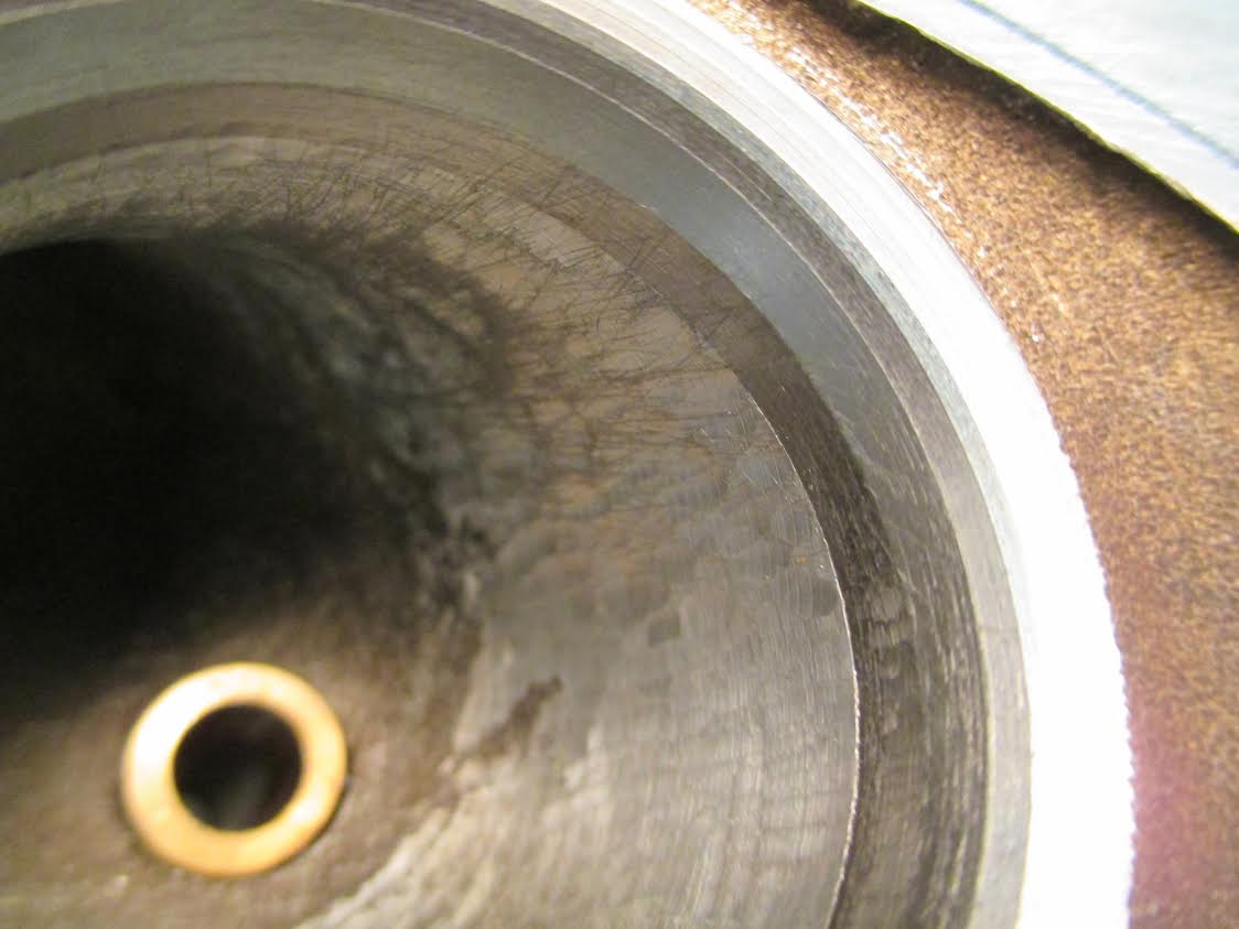
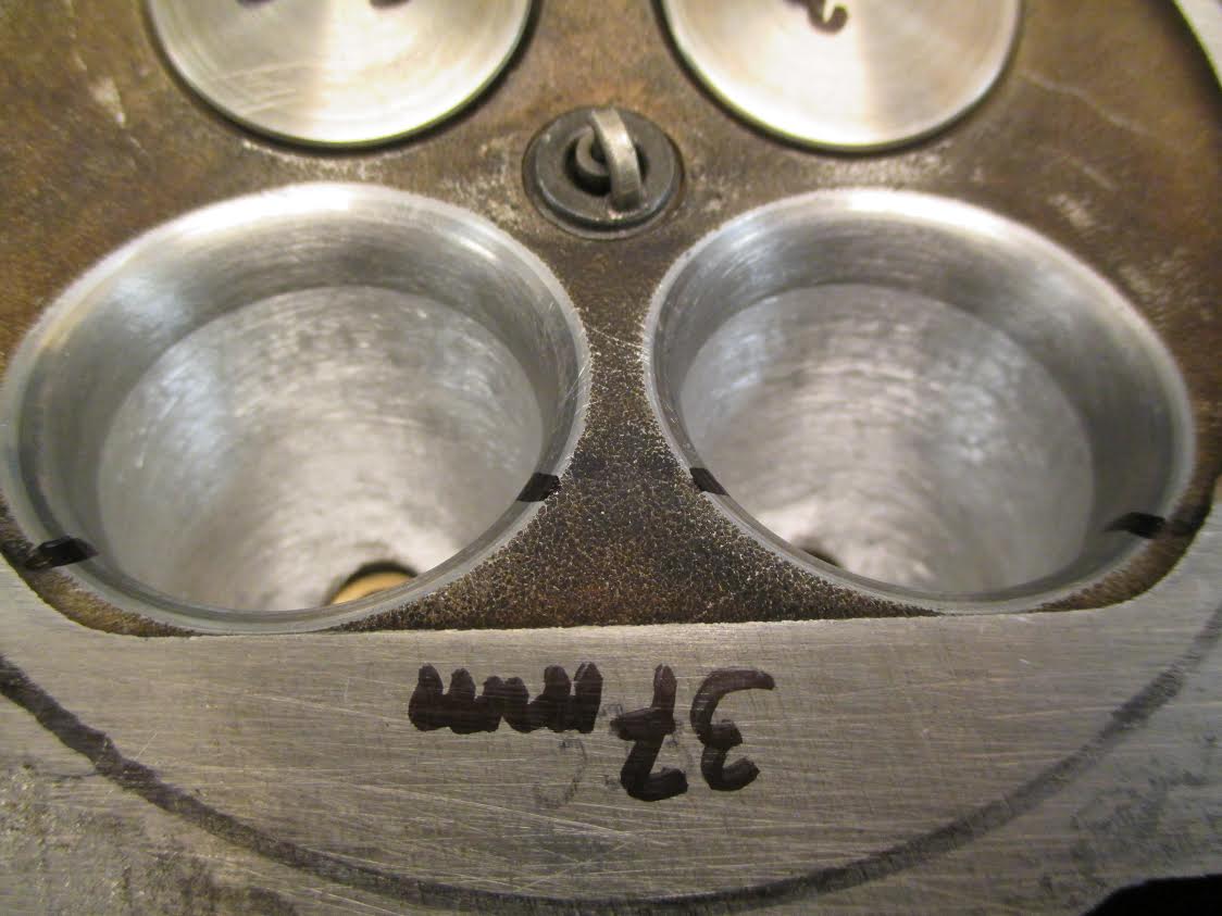
The stock intake port, the valve seats, the throat to valve ratio and the stock intake valves are well designed by the factory to match the low lift stock cams.
For the budget porting, the modification of the stock parts (valves, valve seats and port) for optimum flow I still have a couple of tests to perform before it is all
finished.
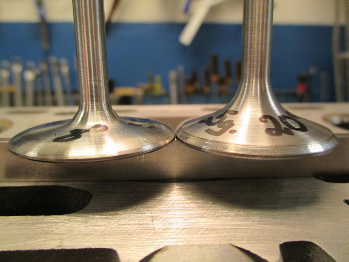
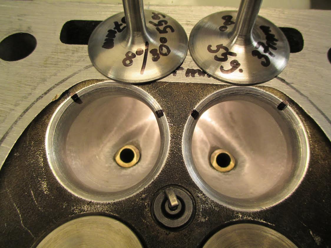
The picture show three different shapes of the stock 37mm intake valve. From left to right:
- Nail shaped, back angle 8 degrees, back cut 30 degrees, seat 1,0mm, small head to stem radius, low weight 55 grams.
- Back angle 20 degrees, back cut 30 degrees, seat 1,0mm.
- Stock valve back angle 20 degrees, seat 2,0+mm, weight 65 grams.
�ke
01-16-2015, 05:10 PM
#228
Nordschleife Master
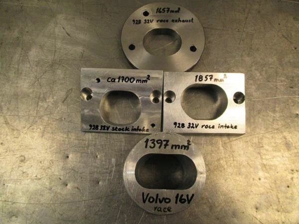
The approximate cross-sectional areas for the stock 37mm valve intake port are:
- Intake port at the flange 1700 mm2
- Divided port where the divider wall starts [2*750, 2*850] = [1500, 1700] mm2
- Divided port where the valve guide is protruding, adjusted for the valve stems [2*(871 - 33) = 2* 838 = 1676 mm2
- At the valve seat ring 2*(750-33) = 1434 mm2
The port shrinks down nicely in cross-sectional area, but at high lifts there's no in-port diffuser for pressure recovery. It's fine for the stock heads with stock S4 cams with their low lift, but with higher lift cams the port shape leaves money on the table.
Cross-sectional areas for Ake's minimum modification 39mm valve intake port:
- Intake port at the flange 1700 mm2
- Divided port where the divider wall starts [2*750, 2*850] = [1500, 1700] mm2
- Divided port where the valve guide is protruding, adjusted for the valve stems [2*(871 - 33) = 2* 838 = 1676 mm2
- At the valve seat ring 2*(908-33) = 1750 mm2
With 39mm valves and larger throats with no other modifications, the port cross-sectional areas set up a pretty much ideal venturi with expanding cross-sectional area after the minimum cross-sectional area. This means that the port is going to flow very well at high lifts. Given the shapes, I believe it is virtually impossible to install 39mm valves on a 928 S4 head with just blending the seat rings to the port and not have the ports flow more air on a flow bench. I am not creative enough to think of a way to get them to flow less on a flow bench.
With stock S4 cams one will not necessarily benefit from this "39mm minimum modifications port" venturi shape, but one will definitely benefit from the increased curtain area of 39mm valves at low and mid lifts. With high lift cams one benefits both from the increased curtain area at low and mid lifts and the the increased high-lift flow due to the larger throat and the beneficial diffuser shape.
These 928 heads have a lot of power potential, if mated with good intake runners and high lift cams.
Last edited by ptuomov; 01-24-2015 at 12:00 PM. Reason: Updated more accurately measured cross-sectional areas
01-17-2015, 05:36 AM
#229
Rennlist Member
Join Date: Feb 2011
Location: Mostly in my workshop located in Sweden.
Posts: 2,230
Received 463 Likes
on
248 Posts
One of the reasons why the 39mm valves flow so well on a 928 head with minimum other modifications is that the cross-sectional areas line up about perfectly for high-lift flow with the 39mm valves.
The approximate cross-sectional areas for the stock 37mm valve intake port are:
- Intake port at the flange 1700 mm2
- Divided port where the divider wall starts 2*700 = 1400 mm2
- Divided port where the valve guide is protruding, adjusted for the valve stems 2*(750-33) = 1434 mm2
- At the valve seat ring 2*(750-33) = 1434 mm2
The port shrinks down nicely in cross-sectional area, but at high lifts there's no in-port diffuser for pressure recovery. It's fine for the stock heads with stock S4 cams with their low lift, but with higher lift cams the port shape leaves money on the table.
Cross-sectional areas for Ake's minimum modification 39mm valve intake port:
- Intake port at the flange 1700 mm2
- Divided port where the divider wall starts 2*700 = 1400 mm2
- Divided port where the valve guide is protruding 2*(750-33) = 1434 mm2
- At the valve seat ring 2*(908-33) = 1750 mm2
With 39mm valves and larger throats with no other modifications, the port cross-sectional areas set up a pretty much ideal venturi with expanding cross-sectional area after the minimum cross-sectional area. This means that the port is going to flow very well at high lifts.
With stock S4 cams one will not necessarily benefit from this "39mm minimum modifications port" venturi shape, but one will definitely benefit from the increased curtain area of 39mm valves at low and mid lifts. With high lift cams one benefits both from the increased curtain area at low and mid lifts and the the increased high-lift flow due to the larger throat and the beneficial diffuser shape.
These 928 heads have a lot of power potential, if mated with good intake runners and high lift cams.
�ke
PS Forgot to say you are a good school teacher, Tuomo. Keep up the good work teaching the crowd. For the ones who like to know more about the basics of cylinder head porting have a look here. http://en.wikipedia.org/wiki/Cylinder_head_porting
Last edited by Strosek Ultra; 01-17-2015 at 05:57 AM.
01-17-2015, 08:51 AM
#230
Nordschleife Master
Thanks Ake! As the saying goes, "Those who can't do, teach." ;-) A corollary to that here in the US is that "And those who can't teach, teach gym."
In any case, for the group's benefit, here are some photos of Ake's plates that he's made after calculating the correct cross-sectional areas for the intake flange. There are some photos of the flow-bench test bellmouth as well. The bellmouth is for testing, but ideally you'd run something similar (with possibly a longer runner) in the live engine. The problem, as always, would be closing the hood...
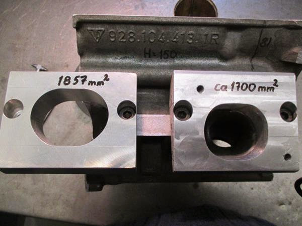
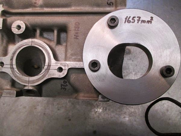
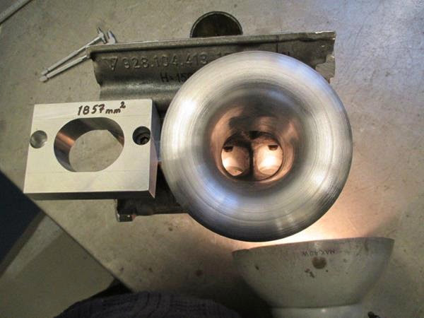
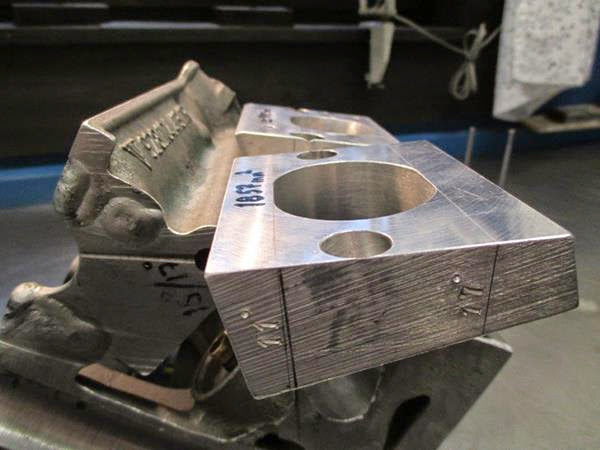
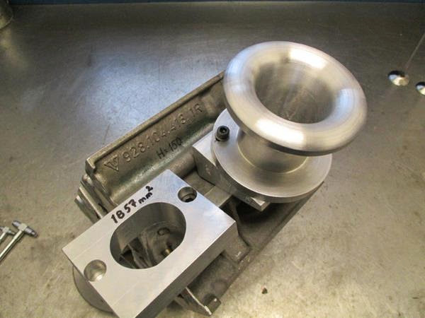
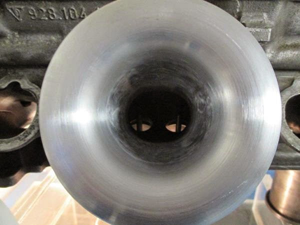
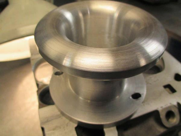
In any case, for the group's benefit, here are some photos of Ake's plates that he's made after calculating the correct cross-sectional areas for the intake flange. There are some photos of the flow-bench test bellmouth as well. The bellmouth is for testing, but ideally you'd run something similar (with possibly a longer runner) in the live engine. The problem, as always, would be closing the hood...
01-17-2015, 09:22 AM
#231
Three Wheelin'
First time I noticed a casting number in your pictures. Have you found any difference in flow among the different casting numbers? Does it make any difference from a starting point which casting you use, only considering flow or potential flow?
01-17-2015, 09:41 AM
#232
Rennlist Member
Join Date: Feb 2011
Location: Mostly in my workshop located in Sweden.
Posts: 2,230
Received 463 Likes
on
248 Posts
�ke
01-17-2015, 12:57 PM
#233
Nordschleife Master
As I may have mentioned, my computer motherboard burned down a week ago. I lost all my data, which are being recovered and should be back on Tuesday. I dropped the computer about a year and a half ago and cracked the case. The cracked case reduced the fan cooling efficiency and the computer started heating up. I was too busy (i.e., lazy) to do anything about it until it was too late. I had set up an automatic backup of everything to a secure location, but I run out of space about a year ago and the backups stopped. I was too busy (i.e., lazy) to do anything about that either. So now I am out $650 and a week of idle time while the data are recovered.
So, long story longer... I am skiing today. It's -20C/-4F at the base and -25C/-13F at the summit at Mt. Mansfield here at Stowe. The sun is shining, though, and with proper clothing skiing is fun. I am taking a break after each hour of skiing to say warm. Going out the third time for the day soon.
In the meanwhile, I used my break to rewrite a spreadsheet that I've used to analyze flow data. It computes and displays three things.
First, the flow at tested pressure, which is trivial.
Second, it computes a "compound restriction equivalent area" for the port. It's a somewhat complex function of three areas: Valve curtain area (depends on lift), throat area, and the upstream port minimum cross-sectional area (MCSA). The formula is really just a rule of thumb, a good starting point for what a typical port will probably flow at each lift. What is interesting is them comparing the actual flow with this predicted flow. I call the ratio efficiency. With good shapes you can get over 100%, but it's hard.
Third, it computes the velocity at smallest point of the port, or the MCSA. The MSCA itself and its location are functions of lift and port shape. At low lifts, the MSCA is at the valve seat. At high lifts, it's either at the valve throat or upstream in the port, depending on the port geometry.
How to interpret these data? You want the right amount of flow for your engine size and your cams at the right lifts. Then, among the ports that give you that flow, you usually want those that are the most efficient and produce the highest velocity at the lifts where the cam spends its time.
For example, just eyeballing it, Ake's minimum modifications 39mm valve heads look really nice in every way for an engine with a straight runner intake manifold/ITBs and Webcam 278/264 camshafts (http://www.webcamshafts.com/mobile/a...71_000687.html).
01-17-2015, 02:19 PM
#234
Rennlist Member
Thread Starter

I wonder how F1 has dealt with their science of port flow with the reintroduction of turbos.
01-17-2015, 06:24 PM
#235
Nordschleife Master
The passenger car problem that they are trying to solve is best described in the SAE paper:
http://papers.sae.org/2011-01-0337/
2011-01-0337
Published:
2011-04-12
DOI:
10.4271/2011-01-0337
Citation:
Agarwal, A., Jung, H., Byrd, K., Stein, R. et al., "Blowdown Interference on a V8 Twin-Turbocharged Engine," SAE Int. J. Engines 4(1):202-218, 2011, doi:10.4271/2011-01-0337.
Author(s):
Apoorv Agarwal
Hosuk Jung
Kevin Byrd
Robert A. Stein
Ahmad Kassem
Paul Whitaker
Christian Spanner
Affiliated:
Ford Motor Co.
AVL Powertrain Engineering Inc.
AVL List GmbH
Abstract:
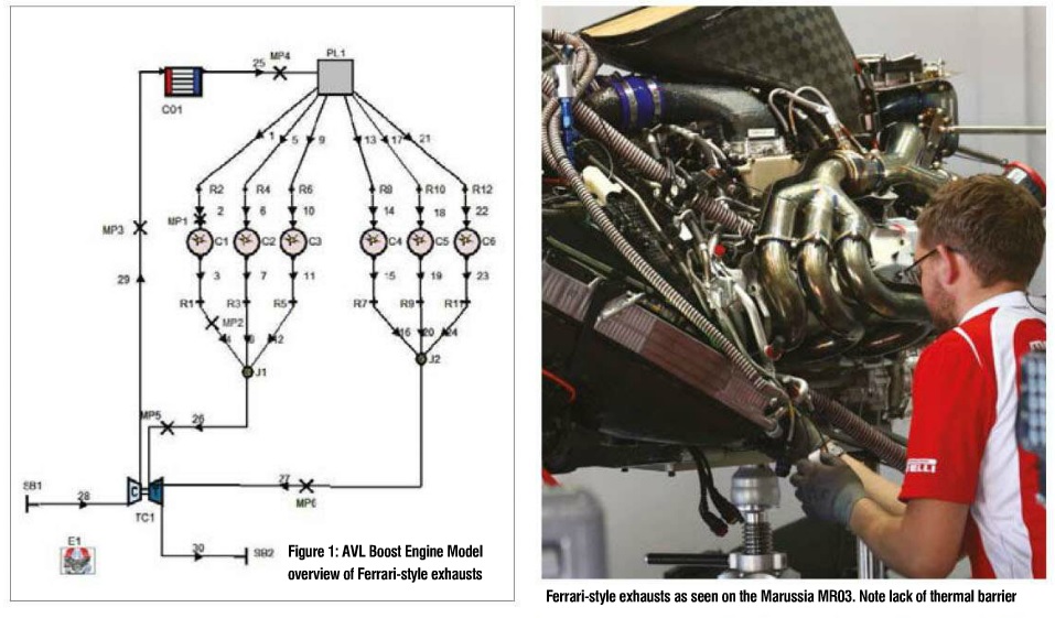
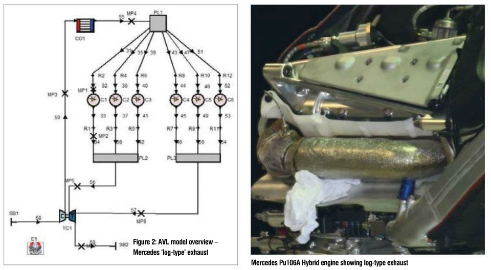
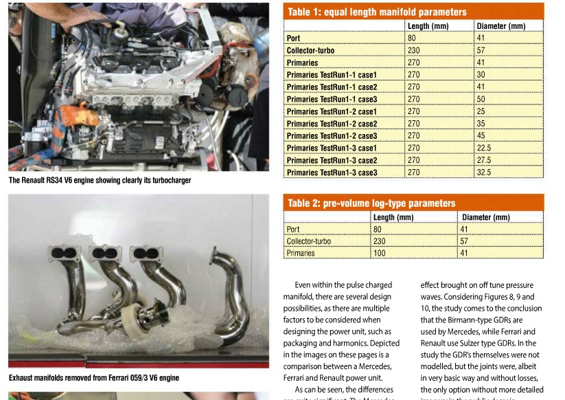
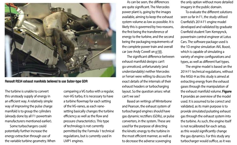
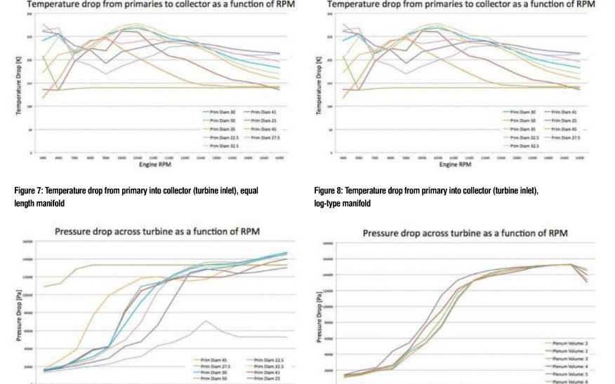
The exhaust blowdown pulse from each cylinder of a multi-cylinder engine propagates through the exhaust manifold and can affect the in-cylinder pressure of other cylinders which have open exhaust valves. Depending on the firing interval between cylinders connected to the same exhaust manifold, this blowdown interference can affect the exhaust stroke pumping work and the exhaust pressure during overlap, which in turn affects the residual fraction in those cylinders. These blowdown interference effects are much greater for a turbocharged engine than for one which is naturally aspirated because the volume of the exhaust manifolds is minimized to improve turbocharger transient response and because the turbines restrict the flow out of the manifolds.
The uneven firing order (intervals of 90�-180�-270�-180�) on each bank of a 90� V8 engine causes the blowdown interference effects to vary dramatically between cylinders. These effects are illustrated in this paper for a twin-turbocharged engine with single scroll turbochargers and log style exhaust manifolds. An AVL tool called Gas exchange and Combustion Analysis (GCA) is used to estimate residual fraction for each cylinder based on measured intake port, cylinder pressure, and exhaust port pressure profiles. The uneven firing interval causes imbalance between cylinders in residual fraction (increasing knock), fresh air (increasing CO due to uneven air-fuel ratio), and pumping work. These effects also preclude running high overlap for scavenging at low rpm, and diminish the potential benefits of dual cam phasing at part load.
The advantages and disadvantages of various methods to diminish the magnitude of these effects are investigated through 1D performance simulation and engine dynamometer testing, including the use of twin scroll turbochargers, exhaust camshafts with different exhaust valve opening timings on pairs of cylinders, and a balance tube between exhaust manifolds.
Published:
2011-04-12
DOI:
10.4271/2011-01-0337
Citation:
Agarwal, A., Jung, H., Byrd, K., Stein, R. et al., "Blowdown Interference on a V8 Twin-Turbocharged Engine," SAE Int. J. Engines 4(1):202-218, 2011, doi:10.4271/2011-01-0337.
Author(s):
Apoorv Agarwal
Hosuk Jung
Kevin Byrd
Robert A. Stein
Ahmad Kassem
Paul Whitaker
Christian Spanner
Affiliated:
Ford Motor Co.
AVL Powertrain Engineering Inc.
AVL List GmbH
Abstract:
The exhaust blowdown pulse from each cylinder of a multi-cylinder engine propagates through the exhaust manifold and can affect the in-cylinder pressure of other cylinders which have open exhaust valves. Depending on the firing interval between cylinders connected to the same exhaust manifold, this blowdown interference can affect the exhaust stroke pumping work and the exhaust pressure during overlap, which in turn affects the residual fraction in those cylinders. These blowdown interference effects are much greater for a turbocharged engine than for one which is naturally aspirated because the volume of the exhaust manifolds is minimized to improve turbocharger transient response and because the turbines restrict the flow out of the manifolds.
The uneven firing order (intervals of 90�-180�-270�-180�) on each bank of a 90� V8 engine causes the blowdown interference effects to vary dramatically between cylinders. These effects are illustrated in this paper for a twin-turbocharged engine with single scroll turbochargers and log style exhaust manifolds. An AVL tool called Gas exchange and Combustion Analysis (GCA) is used to estimate residual fraction for each cylinder based on measured intake port, cylinder pressure, and exhaust port pressure profiles. The uneven firing interval causes imbalance between cylinders in residual fraction (increasing knock), fresh air (increasing CO due to uneven air-fuel ratio), and pumping work. These effects also preclude running high overlap for scavenging at low rpm, and diminish the potential benefits of dual cam phasing at part load.
The advantages and disadvantages of various methods to diminish the magnitude of these effects are investigated through 1D performance simulation and engine dynamometer testing, including the use of twin scroll turbochargers, exhaust camshafts with different exhaust valve opening timings on pairs of cylinders, and a balance tube between exhaust manifolds.

 01-18-2015, 09:09 AM
#236
Rennlist Member
Join Date: Feb 2011
Location: Mostly in my workshop located in Sweden.
Posts: 2,230
Received 463 Likes
on
248 Posts
Quote: So, long story longer... I am skiing today. It's -20C/-4F at the base and -25C/-13F at the summit at Mt. Mansfield here at Stowe. The sun is shining, though, and with proper clothing skiing is fun. I am taking a break after each hour of skiing to say warm. Going out the third time for the day soon.
Skiing at -4F seems a little chilly for me. You originating from the nordic countries probably have Viking genes in your blood making it possible for you to stand the cold. Much worse for the islamic refugees coming here from the south. Not long ago a busload of refugees were taken to a refugee camp in the middle of the country. After a whole day in the bus the refugees refused to leave the bus as they thought it was too cold in this country and they were brought too far away from any major city. I take myself to the forehead, think they have to choose between warm Syria with glowing shells around the ears or cold Sweden with snowflakes in the hair.
�ke
01-18-2015, 09:56 AM
#237
Nordschleife Master
Weather is all about equipment. Would've been horrible out there yesterday without the proper gear.
One of the things that I've begun to appreciate when looking at these port-flow experiments by Ake is how much of porting is about choosing to trade off mid lift flow with high lift flow. The throat diameter is one way to do that, and the valve job angles are another way to do that. What I've also come to appreciate is that the throat-to-valve diameter and the angles you put on valve job have to be mechanically related. The cut angles and their widths completely determine the throat diameter.
Let's take one set of valve angles in a seat for a 37mm valve:
This is one of Ake's 37mm valve cutters which is designed to produce good high lift flow.
Here's where the tradeoffs come from. One could make the angle widths (z1, z2, and z3) larger. This would make the air turn more gently, and that would increase flow across the board. The cost of these more gentle turns is that by a mathematical necessity the throat diameter has to go down, which will hurt the high lift flow. It will hurt the high lift flow because the simple overwhelming effect about flow is that a larger hole will flow more air, and wider angles will result in a smaller hole at the throat. Of course, the smaller throat will only start hurting flow meaningfully at lifts at which the curtain area gets close to, matches, or exceeds the throat area. The net result is that wider cuts (larger z's in the spreadsheet) will increase flow up to mid lifts and reduce it after that.
There are three angles here only, so why do I call the above a five-angle valve job? There are two additional cuts in the combustion chamber, usually at least one of which extends out of the seat and into the combustion chamber. With this valve job, you'd have 30 degree and 15 degree cuts on the combustion chamber. Those cuts are important because they don't impact the throat diameter. Instead, they are just limited by the valve size and the bore size, which in this case are not constraints.
01-18-2015, 09:13 PM
#238
Nordschleife Master
The 928 S4 port has a minimum cross-sectional area (assume high enough lift) of about 1400 mm^2 (2.17 sqin). At the gasket flange, the area is about 1700 mm^2 (2.64 sqin).
Like most 4-valve intake ports from that era, these are very large cross-sectional areas for 316 hp motor. The car factories didn't have idiots or children as engineers then, so obviously this design philosophy achieved something along the lines of flat torque curves, low fuel consumption, etc. However, from a pure performance perspective the ports are too large.
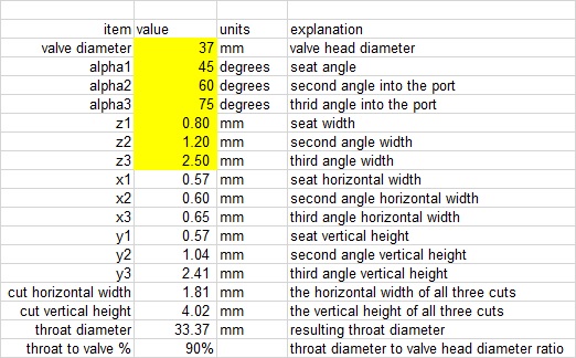
Pipemax is an excellent $45 program that helps estimate ideal port and intake dimensions. Here's what pipemax would recommend for this engine, S4 at peak power rpm producing about 316hp:
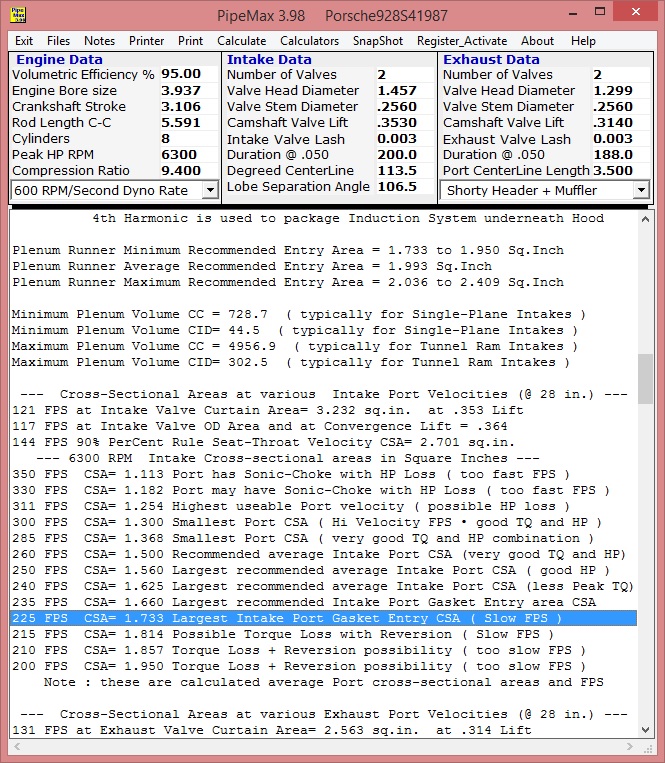
Recommendations range from 840 mm^2 (1.3 sqin) to 1115 mm^2 (1.73 sqin). That's a lot smaller than the actual port.
One could also ask how much hp could the stock ports support. Playing with pipemax, these ports would be generously sized for a 500 hp engine:
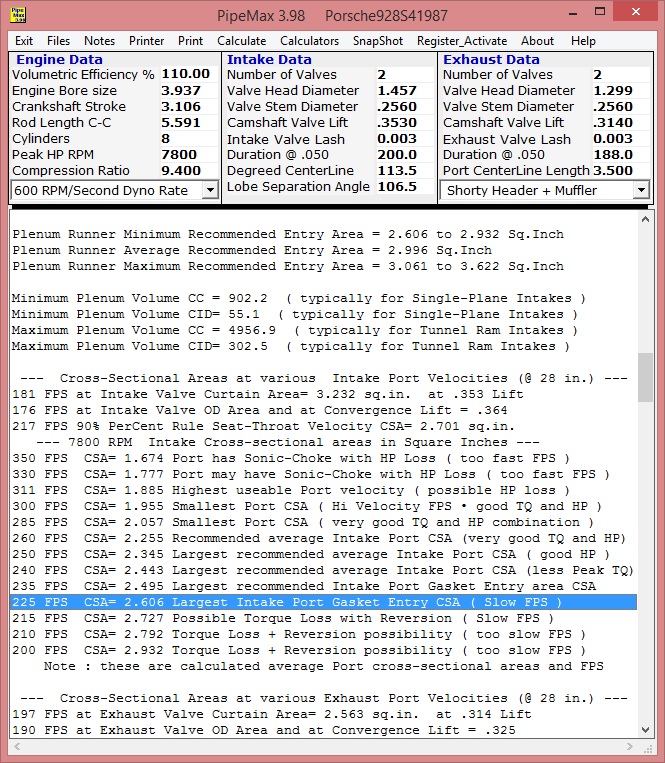
The above experiment run the 5.0L motor at 7800 rpm at 110% VE producing 505-530hp, which is probably not happening with stock S4 bottom end or with stock S4 intake manifold.
What's the conclusion?
So the ports are large and shouldn't be made any larger below 500 hp normally aspirated. It's not a terribly big deal for most uses, so what if the air speed is too slow.
Ake, however, is used to building high performance N/A engines that maximize their potential. These port sizes are too large in any engine producing under 500 hp for him to use high-overlap cams, high compression, and tuned headers to maximize the engine because the intake air speed is too slow for the maximum performance gas exchange.
I use turbos, baby girl cams, etc. which are much more forgiving of anything on the intake side as long as the exhaust side is A-Ok.
Like most 4-valve intake ports from that era, these are very large cross-sectional areas for 316 hp motor. The car factories didn't have idiots or children as engineers then, so obviously this design philosophy achieved something along the lines of flat torque curves, low fuel consumption, etc. However, from a pure performance perspective the ports are too large.
Pipemax is an excellent $45 program that helps estimate ideal port and intake dimensions. Here's what pipemax would recommend for this engine, S4 at peak power rpm producing about 316hp:
Recommendations range from 840 mm^2 (1.3 sqin) to 1115 mm^2 (1.73 sqin). That's a lot smaller than the actual port.
One could also ask how much hp could the stock ports support. Playing with pipemax, these ports would be generously sized for a 500 hp engine:
The above experiment run the 5.0L motor at 7800 rpm at 110% VE producing 505-530hp, which is probably not happening with stock S4 bottom end or with stock S4 intake manifold.
What's the conclusion?
So the ports are large and shouldn't be made any larger below 500 hp normally aspirated. It's not a terribly big deal for most uses, so what if the air speed is too slow.
Ake, however, is used to building high performance N/A engines that maximize their potential. These port sizes are too large in any engine producing under 500 hp for him to use high-overlap cams, high compression, and tuned headers to maximize the engine because the intake air speed is too slow for the maximum performance gas exchange.
I use turbos, baby girl cams, etc. which are much more forgiving of anything on the intake side as long as the exhaust side is A-Ok.
01-19-2015, 07:27 PM
#239
Nordschleife Master
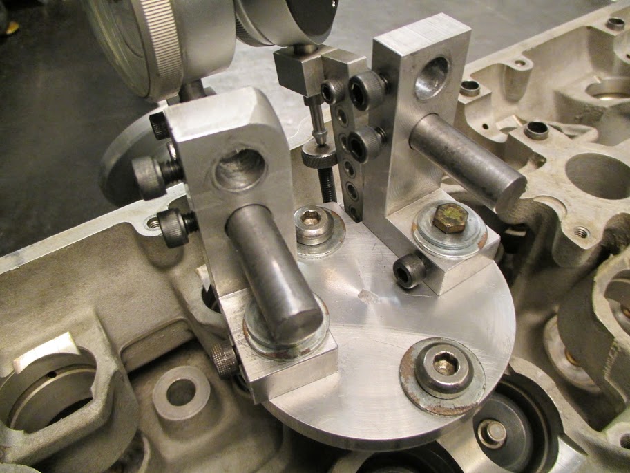
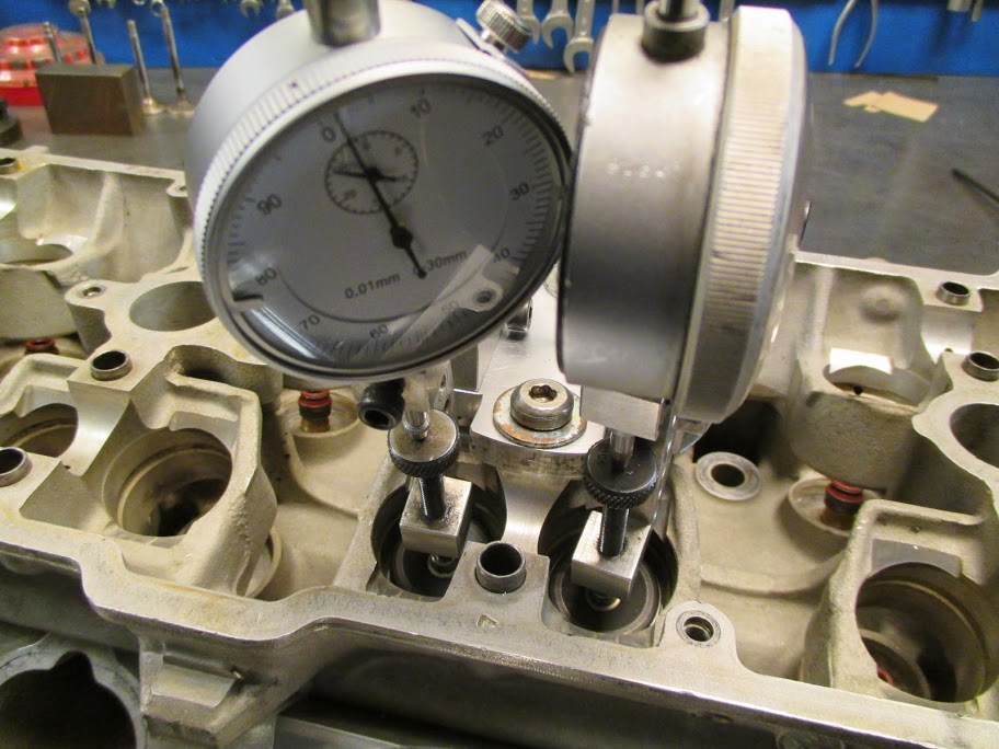
By the way, the ability perform a large number of comparable head-flow tests accurately requires controlling a lot of variables. One of the more important variables is valve lift (duh!). Here are two photos of Ake's tool for controlling the valve lift of the 928 4-valve head. Figured out I'd post those since the thread title promised cool pics throughout! ;-)
01-20-2015, 09:38 AM
#240
Nordschleife Master
As this is the porting and polishing by committee thread, I have volunteered to some secretarial duties. Ake has been working on the stock S4 port and valves to see how much flow improvement one can generate without the expense of new seats and valves. This doesn't mean that the 39mm valves wouldn't be better for large high rpm engines, they would be. This is in the original spirit of the thread of what can be done when the heads are off without new, expensive components. And just to remind everyone, I've done none of the work, it's all Ake's efforts and expertise. I am just documenting.
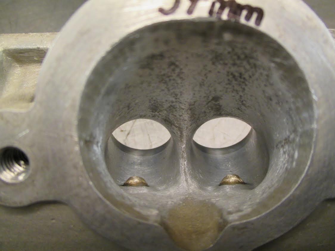
2x37mm valve flow study
The below describes some beneficial modifications to the 928 S4 heads. The figures in the bottom of the post show three ways to interpret the test data from Ake's experiments with 37mm intake valves, to see how beneficial and under which conditions various modifications are.
There are three select experiments, all three evaluated in each of the three graphs. All experiments are on a 100mm bore and in comparable conditions.
The first experiment is labeled "STOCK INTAKE PORT 2x37mm, stock valves". This is as the head and the valves came from the factory.
The second experiment is labeled "BUDGET INTAKE PORT 2x37mm, stock valves". This is tested combination #16 in Ake's data set.
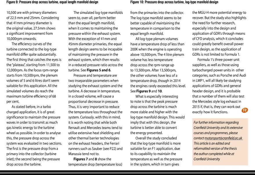
The only change is a five-angle valve job that gives a larger throat diameter which is then blended to the port. In particular, this experiment is run with unmodified stock 2x37mm intake valves. Valve seat ring ID increased to 33.3mm (90% of the valve size). Cross sectional area (CSA) at the throat per valve is 871 - 33 = 838 mm^2. Valve seat angle 45 degrees x width 0.8mm. Upstream the port 60 degrees x 1,2mm width and 75 degrees x 2,5mm. The upstream port matched to the increased seat ring ID. In the combustion chamber, 32.5 degrees x 1.2mm and 15 degrees x 0.5mm cuts.
The third experiment is labeled "BUDGET INTAKE PORT 2x37mm, radiused cuts, short-side and long side modified, modified valves". This is tested combination #26 in Ake's data set. Modified intake port with 2 x 37mm modified valves.
The starting point is the same valve job as in the second experiment (Ake's #16). The bottom two cuts are then radiused and rounded.
There are many opinions about radiusing intake valve job angles. The consensus among writers appears to be that it usually hurts with carb'd 2-valve engines and may hurt or help with fuel-injected 4-valve engines. How much and how far downstream to radius, if at all, depends on how important it is to reduce reversion for the engine in question. Leaving the sharp edges in supposedly reduces reversion. From the flow perspective, radiusing has at most a marginal effect.
Valves are modified. Nail-shaped flat valve, back angle of 8 degrees and back cut of 30 degrees. Valve back rounded and smoothed, the 45-degree valve seat in the valve reduced from over 2mm in the stock valve to 1.0mm in the modified valve. The valve weight goes down as a positive by-product.
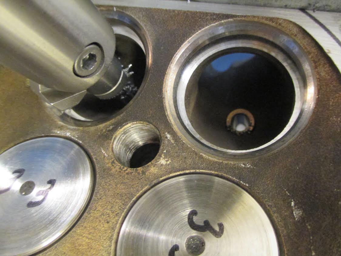
In addition, the port small-side radius is moved 1mm closer to the seat. The purpose of this modification is to increase the short-side radius, allowing air to turn more gently. The modification is made between 10:30am and 2pm on the left hand side and between 10am and 1:30pm on the right hand side valve. This will increase the valve throat somewhat upstream of the blended cuts, the distance between the short side and long side is 34.3mm.

The above short-side radius optimization is in my opinion the most challenging part of the third experiment. There are conflicting requirements of keeping the cross-sectional area down, providing air a straight section before the seat to settle down, and increasing the short-side turn radius. Ake can probably give much more detail on this step if readers so desire.
The long-side radius is also modified by making the divided ports slightly wider and taller in the area where the valve guide is protruding.
In terms of numbers, here is some guidance to what the cross-sectional areas are supposed measure at after these modifications:
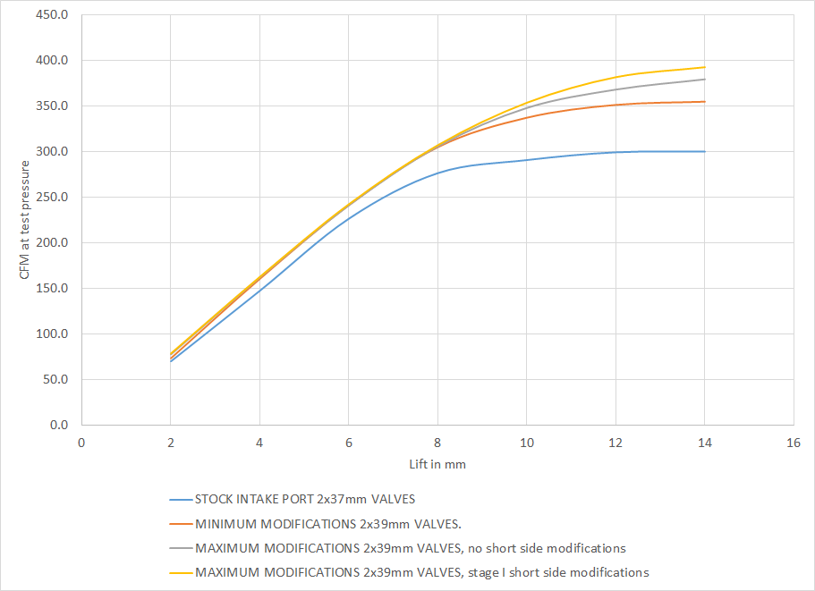
Here are the flow results from the three experiments:
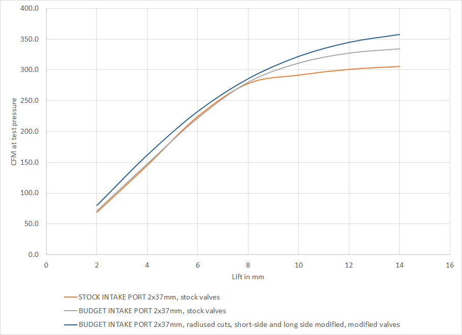
The first experiment has no surprises, since it is the stock port.
The second experiment increases the throat-to-valve diameter ratio, which helps the high lift flow but at best doesn't lose any low-mid and mid-lift flow. Still, with big cams, the second experiment is already a big improvement. With small cams, not so much.
The third experiment involves a lot more time-consuming modifications. The flow results show that those are worth it. Basically, the third experiment takes the flow curve from the second experiment and shifts it up across the lift range. This is a very impressive result with 37mm valves. Flow rates of 350+ CFM at 28 inches of water stand comparison against most other ported 928 heads, regardless of the valve size.
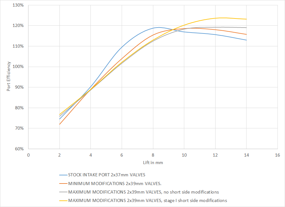
In terms of port efficiency, the picture is similar. Recall that the below graph defines port efficiency as the ratio of actual flow to the predicted flow from a simple compound restriction formula that takes into account the valve curtain area and the throat area.
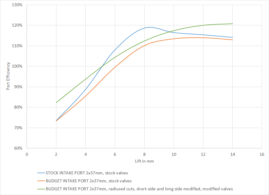
The stock port is very efficient at the 5-9mm lift range. This is mainly due to the very low 83% throat-to-valve diameter ratio. If one is limited to low lift cams, then one should modify Ake's valve job angles that result in a slightly smaller throat-to-valve diameter ratio.
The third experiment is more efficient everywhere than the second experiment. Again, the modifications are paying off.
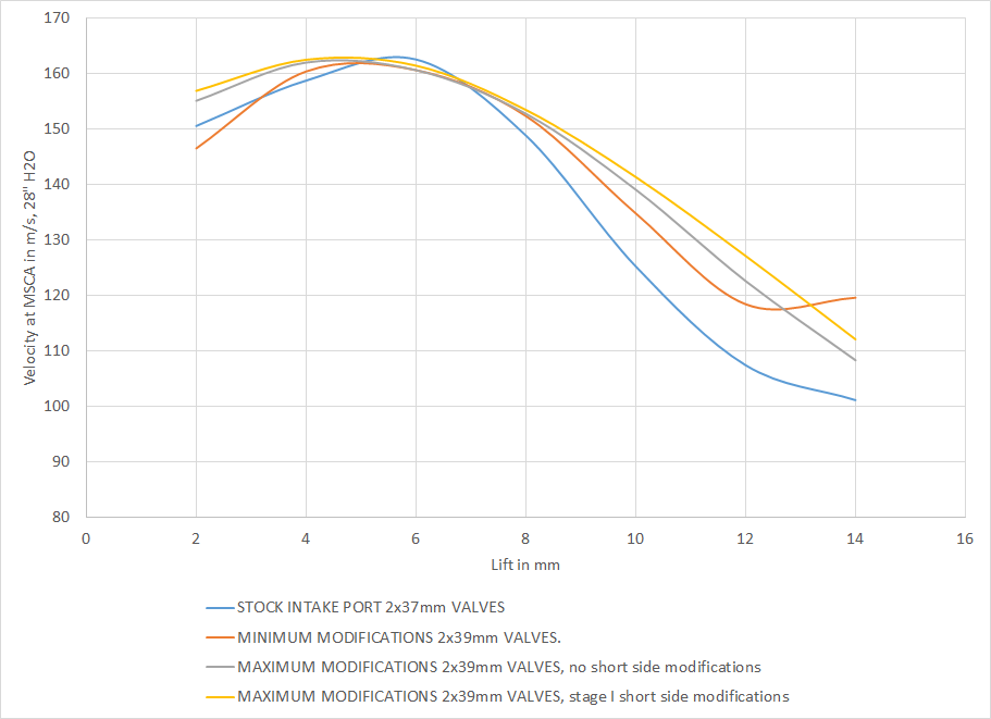
The final graph is port velocity at its fastest point. This is not the velocity of the port in a running engine, instead it's the computed velocity at the flow bench. One could also directly measure velocity at some points with a pitot-static probe, but this is not that kind of velocity. It's simply the flow rate vs. the minimum cross-sectional area.
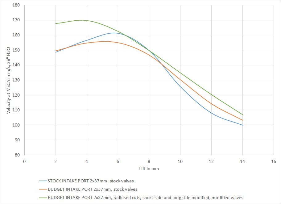
Based on Ake's comments, I've edited the upstream CSA estimates for the ports. I am using 1528 mm^2 for the first two experiments and 1738 mm^2 for the third experiment. Downstream I am accounting for the seat ring area and the valve curtain area. Since the MCSA resides mostly at the curtain area or seat ring area, the velocity curves above aren't very sensitive to these measurements.
As one would guess based on the efficiency graphs, the stock port has high velocity at the minimum cross-sectional area (MCSA) at 4-9mm lifts. Also as expected, the 90% throat valve job loses to the stock port in velocity below 9mm and beats it above. Impressively, the third experiment matches the stock port in velocity at 6-7mm lifts and beats it rather clearly both below and above that lift range.
My personal conclusion from Ake's study: These experiments show that one can improve the 928 4-valve ports with some thoughtful modifications expertly implemented with good tools, without having to buy expensive trick parts.
2x37mm valve flow study
The below describes some beneficial modifications to the 928 S4 heads. The figures in the bottom of the post show three ways to interpret the test data from Ake's experiments with 37mm intake valves, to see how beneficial and under which conditions various modifications are.
There are three select experiments, all three evaluated in each of the three graphs. All experiments are on a 100mm bore and in comparable conditions.
The first experiment is labeled "STOCK INTAKE PORT 2x37mm, stock valves". This is as the head and the valves came from the factory.
The second experiment is labeled "BUDGET INTAKE PORT 2x37mm, stock valves". This is tested combination #16 in Ake's data set.
The only change is a five-angle valve job that gives a larger throat diameter which is then blended to the port. In particular, this experiment is run with unmodified stock 2x37mm intake valves. Valve seat ring ID increased to 33.3mm (90% of the valve size). Cross sectional area (CSA) at the throat per valve is 871 - 33 = 838 mm^2. Valve seat angle 45 degrees x width 0.8mm. Upstream the port 60 degrees x 1,2mm width and 75 degrees x 2,5mm. The upstream port matched to the increased seat ring ID. In the combustion chamber, 32.5 degrees x 1.2mm and 15 degrees x 0.5mm cuts.
The third experiment is labeled "BUDGET INTAKE PORT 2x37mm, radiused cuts, short-side and long side modified, modified valves". This is tested combination #26 in Ake's data set. Modified intake port with 2 x 37mm modified valves.
The starting point is the same valve job as in the second experiment (Ake's #16). The bottom two cuts are then radiused and rounded.
There are many opinions about radiusing intake valve job angles. The consensus among writers appears to be that it usually hurts with carb'd 2-valve engines and may hurt or help with fuel-injected 4-valve engines. How much and how far downstream to radius, if at all, depends on how important it is to reduce reversion for the engine in question. Leaving the sharp edges in supposedly reduces reversion. From the flow perspective, radiusing has at most a marginal effect.
Valves are modified. Nail-shaped flat valve, back angle of 8 degrees and back cut of 30 degrees. Valve back rounded and smoothed, the 45-degree valve seat in the valve reduced from over 2mm in the stock valve to 1.0mm in the modified valve. The valve weight goes down as a positive by-product.
In addition, the port small-side radius is moved 1mm closer to the seat. The purpose of this modification is to increase the short-side radius, allowing air to turn more gently. The modification is made between 10:30am and 2pm on the left hand side and between 10am and 1:30pm on the right hand side valve. This will increase the valve throat somewhat upstream of the blended cuts, the distance between the short side and long side is 34.3mm.
The above short-side radius optimization is in my opinion the most challenging part of the third experiment. There are conflicting requirements of keeping the cross-sectional area down, providing air a straight section before the seat to settle down, and increasing the short-side turn radius. Ake can probably give much more detail on this step if readers so desire.
The long-side radius is also modified by making the divided ports slightly wider and taller in the area where the valve guide is protruding.
In terms of numbers, here is some guidance to what the cross-sectional areas are supposed measure at after these modifications:
- CSA at seat ring ID 871+ 30 - 33 = 868 mm^2.
- CSA at valve guide 855 + 30 + 30 - 33 = 869 mm^2.
- CSA where the divided ports begin 804 + 36 + 54 - 20 = 874 mm^2.
Here are the flow results from the three experiments:
The first experiment has no surprises, since it is the stock port.
The second experiment increases the throat-to-valve diameter ratio, which helps the high lift flow but at best doesn't lose any low-mid and mid-lift flow. Still, with big cams, the second experiment is already a big improvement. With small cams, not so much.
The third experiment involves a lot more time-consuming modifications. The flow results show that those are worth it. Basically, the third experiment takes the flow curve from the second experiment and shifts it up across the lift range. This is a very impressive result with 37mm valves. Flow rates of 350+ CFM at 28 inches of water stand comparison against most other ported 928 heads, regardless of the valve size.
In terms of port efficiency, the picture is similar. Recall that the below graph defines port efficiency as the ratio of actual flow to the predicted flow from a simple compound restriction formula that takes into account the valve curtain area and the throat area.
The stock port is very efficient at the 5-9mm lift range. This is mainly due to the very low 83% throat-to-valve diameter ratio. If one is limited to low lift cams, then one should modify Ake's valve job angles that result in a slightly smaller throat-to-valve diameter ratio.
The third experiment is more efficient everywhere than the second experiment. Again, the modifications are paying off.
The final graph is port velocity at its fastest point. This is not the velocity of the port in a running engine, instead it's the computed velocity at the flow bench. One could also directly measure velocity at some points with a pitot-static probe, but this is not that kind of velocity. It's simply the flow rate vs. the minimum cross-sectional area.
Based on Ake's comments, I've edited the upstream CSA estimates for the ports. I am using 1528 mm^2 for the first two experiments and 1738 mm^2 for the third experiment. Downstream I am accounting for the seat ring area and the valve curtain area. Since the MCSA resides mostly at the curtain area or seat ring area, the velocity curves above aren't very sensitive to these measurements.
As one would guess based on the efficiency graphs, the stock port has high velocity at the minimum cross-sectional area (MCSA) at 4-9mm lifts. Also as expected, the 90% throat valve job loses to the stock port in velocity below 9mm and beats it above. Impressively, the third experiment matches the stock port in velocity at 6-7mm lifts and beats it rather clearly both below and above that lift range.
My personal conclusion from Ake's study: These experiments show that one can improve the 928 4-valve ports with some thoughtful modifications expertly implemented with good tools, without having to buy expensive trick parts.
Last edited by ptuomov; 01-20-2015 at 06:53 PM.