

PLEASE HELP....PO modified wiring?

Rennlist Member
Joined: Jan 2004
Posts: 12,620
Likes: 8
From: Boulder Creek, CA
It looks like the 30 position on the VIII relay plug - Did I get that backwards as well? Anway, He can test whether that plug position provides 12V at all times or not. If he moved that inadvertently, as he says he had things somewhat disconnected, then all bets are off.
Since he loses the instruments when the relay is disconnected, I assume this contraptioon was rigged to supply switched power to the instruments, as H7 is supposed to do and not to feed the headlamp washers.
Since he loses the instruments when the relay is disconnected, I assume this contraptioon was rigged to supply switched power to the instruments, as H7 is supposed to do and not to feed the headlamp washers.
Also, relays generally are laid out as follows:
Code:
         -- (86)
- (30)  | (87a)  | (87)
         -- (85)

Where:
30 is "common"
85 & 86 are "coil"
87 & 87a are some combination of NO & NC.
I agree with your overall assessment of what's impacted by the change, I was just looking for more specific info as the start of point-to-point troubleshooting. For example, if he has continuity from that wire to terminal "O4" as is shown in the wiring diagrams then it's a real head-scratcher; if it's connected to the 30 bus then it makes sense that it is meant to provide power to the gauges, but then the question is, why is that circuit not on the 30 terminal where it belongs?
I find that on the early diagrams the connections are usually per the drawing, not switched(as would be the case if that 87 terminal goes to the fuse). Granted, functionally it doesn't matter, but IMHO it's a bit unusual for the panel to not match the drawing on these early diagrams.
Under the Lift
Lifetime Rennlist
Member
Lifetime Rennlist
Member

Joined: Mar 2002
Posts: 18,648
Likes: 52
From: Buckeye, AZ
I was going by this chart -- pretty sure it's VII.
Also, relays generally are laid out as follows:
The "common" terminal is the one that is horizontal in his pic, and the wiring diagram shows that terminal being connected to fuse 20. The blue wire in his pic is connected to terminal 87(on a basic power relay).
Code:
         -- (86)
- (30)  | (87a)  | (87)
         -- (85)

Where:
30 is "common"
85 & 86 are "coil"
87 & 87a are some combination of NO & NC.
 It almost made sense that way. It makes no sense to be outputting to the washers. So, I'm suspecting that is not exactly where the PO put that wire.
He should start over. Maybe I should to.
If the problem is a failure to power the instruments, H7 did that originally. If H7 no longer provides power, then why is it hooked to the relay?? Since he had this working at one point, then one of these wires reaches the instruments. It seemed to me the red one had to be it, but it still makes little sense. If H7 still provides switched power, I would hook it directly to whatever of the other wires goes to the instruments and be done with it, unless for some reason the current flow from H7 was too low and so it was being used to trip a relay with a better power source. Hey, that almost makes sense.
Last edited by Bill Ball; Mar 12, 2008 at 02:55 PM.
Rennlist Member
Joined: Jan 2004
Posts: 12,620
Likes: 8
From: Boulder Creek, CA
OK, hold the phone... Bill, you prompted me to start over as well, and, uh... it turns out that H7 does NOT power the instruments. The plot sickens.
H7 powers the odometer, the central warning unit, and the alternator charge wire. The common instrument power for lights and gauges comes off of H6, via fuse 12. I went back and read more carefully -- I had picked up on your mention of H7 without checking it myself. In fact Dean is referring to H6 so in this case the symptoms fit the situation of the relay having something to do with the instruments.
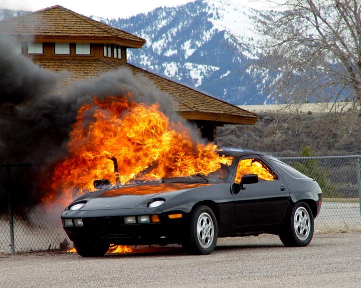
I'm going to make a big assumption here, that assumption being that you do not see +12v on H6 in any key position. If that's the case, it should be corrected properly. Get a look at the back side of the panel as soon as you can so you can correct any issues before they get worse. Motivational picture follows:
Now, Dean, back to your original questions. As for the buzzer, all I can say is track it down and disable it. Now that I've had another look I think I see how to get your instruments working again, but please read through and take special note of the items in bold.
And please keep in mind, my #1 recommendation is to pull the electrical panel and correct whatever is wrong with it. What I offer below should only be considered a temporary fix.
It looks like the relay was initially set up to properly switch power to the instruments, but you need to correct some problems or you can smoke your whole cluster(and maybe parts of the harness) very easily. First thing, See if that red wire is +12v only with the key in "ON" or "START" positions(not "ACC"). If it does not fit that description, you will have to find a place to tap power that DOES fit that description.
Next, if you want to use that relay socket, replace fuse #20, should be 8A rating(that's the correct rating for the instruments). Double-check the relay socket you are plugged into, verify that the #30 terminal(The large horizontal one on the left side of the socket you are plugged into in your first pic) is powered with fuse #20 in place and unpowered with fuse #20 removed.
Now take the wire you have plugged into the relay socket and move it to the #30 terminal. Now you have your fused power to the instruments. Alternatively, you can just put an inline 8A fuse on that wire and connect it to battery(unswitched) power. DO NOT try to power the instruments with an unfused line or with the wrong fuse rating.
Now be sure to tape up the relay connectors so it doesn't short on anything.
That should get you back to where you were, but IMHO you still need to dig to the root cause and fix it. If the PO didn't fix a known problem correctly, who knows what other problems are lurking, so far unnoticed? When an electrical panel gets frapped, sometimes you can correct(or bypass) the obvious problem, but another problem that may initially go unnoticed is that wires can get hot on the back of that panel, hot enough to melt insulation. Then the wires touch, and... well, see pic above. Also, the wires can melt through 99.9% of the insulation and things seem to work fine until one day you hit a bump and end up with a car full of smoke.
H7 powers the odometer, the central warning unit, and the alternator charge wire. The common instrument power for lights and gauges comes off of H6, via fuse 12. I went back and read more carefully -- I had picked up on your mention of H7 without checking it myself. In fact Dean is referring to H6 so in this case the symptoms fit the situation of the relay having something to do with the instruments.
I'm going to make a big assumption here, that assumption being that you do not see +12v on H6 in any key position. If that's the case, it should be corrected properly. Get a look at the back side of the panel as soon as you can so you can correct any issues before they get worse. Motivational picture follows:
Now, Dean, back to your original questions. As for the buzzer, all I can say is track it down and disable it. Now that I've had another look I think I see how to get your instruments working again, but please read through and take special note of the items in bold.
And please keep in mind, my #1 recommendation is to pull the electrical panel and correct whatever is wrong with it. What I offer below should only be considered a temporary fix.
It looks like the relay was initially set up to properly switch power to the instruments, but you need to correct some problems or you can smoke your whole cluster(and maybe parts of the harness) very easily. First thing, See if that red wire is +12v only with the key in "ON" or "START" positions(not "ACC"). If it does not fit that description, you will have to find a place to tap power that DOES fit that description.
Next, if you want to use that relay socket, replace fuse #20, should be 8A rating(that's the correct rating for the instruments). Double-check the relay socket you are plugged into, verify that the #30 terminal(The large horizontal one on the left side of the socket you are plugged into in your first pic) is powered with fuse #20 in place and unpowered with fuse #20 removed.
Now take the wire you have plugged into the relay socket and move it to the #30 terminal. Now you have your fused power to the instruments. Alternatively, you can just put an inline 8A fuse on that wire and connect it to battery(unswitched) power. DO NOT try to power the instruments with an unfused line or with the wrong fuse rating.
Now be sure to tape up the relay connectors so it doesn't short on anything.
That should get you back to where you were, but IMHO you still need to dig to the root cause and fix it. If the PO didn't fix a known problem correctly, who knows what other problems are lurking, so far unnoticed? When an electrical panel gets frapped, sometimes you can correct(or bypass) the obvious problem, but another problem that may initially go unnoticed is that wires can get hot on the back of that panel, hot enough to melt insulation. Then the wires touch, and... well, see pic above.
Also, the wires can melt through 99.9% of the insulation and things seem to work fine until one day you hit a bump and end up with a car full of smoke.

Thread Starter
Drifting
Joined: Feb 2008
Posts: 3,029
Likes: 10
From: Columbus, Mississippi
Hi Dave,
Sorry for the delay...I've been side tracked making a living. ( those bast#$%)
I will follow your lead as per your last. The last thing I want is to end this thread with a similar pic of his car....Its great there are guys like yourself that will take time to help a brother out.
I hope to get under the dash this evening.

Thread Starter
Drifting
Joined: Feb 2008
Posts: 3,029
Likes: 10
From: Columbus, Mississippi
Okay...just an update. The RED wire is actually RED and BLACK. I pulled the panel and followed it back to the section of harness that plugs in the H gang plug. The RED/BLACK is suppose to go SOMEWHERE on that H plug. SO the rely in between the R/B wire into relay then out to H plug. DOES this help anyone???
Last edited by Dean_Fuller; Apr 16, 2010 at 04:22 AM.
Rennlist Member
Joined: Jan 2004
Posts: 12,620
Likes: 8
From: Boulder Creek, CA
The wiring diagram does in fact show that H6 should be red/black. IMHO the next thing to check is, do you get power on the H6 terminal of the CE panel with the key on? You might have a look at the backside of the panel, see where that wire goes and see if it looks healthy. I recommend that before you reconnect the battery and check H6 for power, put the CE panel back in place, with at least one turn on one of the mounting screws so it stays put. Can't be too careful!
If H6 operates as it should and is properly fused via fuse 12, then it's a complete mystery why the relay is even there. (well, more of a mystery anyway)
If H6 operates as it should and is properly fused via fuse 12, then it's a complete mystery why the relay is even there. (well, more of a mystery anyway)
Rennlist Member
Joined: Jan 2004
Posts: 12,620
Likes: 8
From: Boulder Creek, CA
can you provide a pic that better shows how the wires are attached to the relay? Also, did you unplug(and possibly move) the wires on the relay itself, or the wire in the relay socket in the panel? Also, at some point please get a voltmeter and find out what happens with those relay socket terminals with the key in various positions.
Under the Lift
Lifetime Rennlist
Member
Lifetime Rennlist
Member
Joined: Mar 2002
Posts: 18,648
Likes: 52
From: Buckeye, AZ
Dave's on the case. Glad you guys correctly identified this as H6 and not 7. Some of us had the plug terminal numbering upside down.
H6 is another ignition switched (15) output to parts of the instrument panel. Normally the red/black wire would be attached to H6. Instead, the blue wire attached to H6, going to the relay to which the red/black wire is attached. Why and what this accomplishes, I'll leave to Dave. Regardless, H6 (red/black wire) should get ignition switched power. There are lots of sources for this to which the red/black wire could have been attached. That's why I don't get the relay. I'm missing something fundamental. H6 and H7 should have power whenever the ignition is turned on.
H6 is another ignition switched (15) output to parts of the instrument panel. Normally the red/black wire would be attached to H6. Instead, the blue wire attached to H6, going to the relay to which the red/black wire is attached. Why and what this accomplishes, I'll leave to Dave. Regardless, H6 (red/black wire) should get ignition switched power. There are lots of sources for this to which the red/black wire could have been attached. That's why I don't get the relay. I'm missing something fundamental. H6 and H7 should have power whenever the ignition is turned on.
Rennlist Member
Joined: Jan 2004
Posts: 12,620
Likes: 8
From: Boulder Creek, CA
It sounds like a can of worms. This whole issue may be nothing more than a faulty ignition switch that is not powering the 15 bus properly, followed by a lot of Billy Bob "fixes". Or it could be a major problem on the back side of the panel.
First, I'd say closely inspect the back of the panel with the battery disconnected. Take it all the way out or get a strong light, nudge the wires around with something safe like a popsicle stick looking for any signs of melted insulation. Once that's eliminated we can begin to look for other reasons why you're not getting power there, figure out why the heck your alternator works with no power @ H7, etc.
Rennlist Member
Joined: Jan 2004
Posts: 12,620
Likes: 8
From: Boulder Creek, CA