

Defeating the Bulb Control Module
 12-22-2006, 05:52 PM
#16
Drifting
Thread Starter

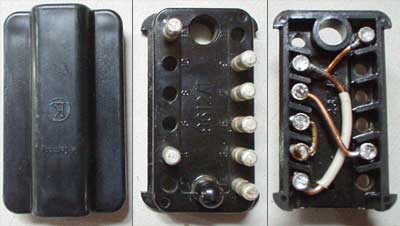
Pulled the module on my 90' S4.
Quite easy to do on the 90' and later cars. The module resides just to the outboard side of the glove box. Simply remove a trangle shaped carpeted piece (three screws), open the glove box door and remove a couple more nuts that hold a bracket in place, and the module drops down along with a alarm module.
The module on my 90' has a later part number, # 928.641.603.10. Taking the cover off.....
- same printed circuit board as in the photo previously posted,
- same component count. Only difference is the ICs are of a different part number.
- uses Telefunken U4791B and 4790B special automotive application ICs.
So, different part number but same basic circuit.
borland
90' S4
 12-22-2006, 05:53 PM
#17
Electron Wrangler
Lifetime Rennlist
Member
Lifetime Rennlist
Member
Borland & Ed - just swapping the load resistors should be enough. The lamp control module just senses that the voltage drop across the resistor when the load is turned on is enough to indicate the bulb is not burned out (and presumably also is not so much you have too powerful of a bulb installed).
So there is a voltage window comparator... however its configured.
So a higher value Rx should work - you'd need some trial & error to determine but a ratio of the Bulb Current:LED Current should be close to the Needed Rx value:Existing Load Rx value. You will not need anything like such a high power load Rx - 2W ceramic should be perfectly OK for a typical LED bulb (but maybe not for a 3W LED version).
Another way to do this is to monitor the voltage across the load Rx's when the correct bulbs are active - then match that voltage drop for your LED's
Alan
12-22-2006, 06:02 PM
#18
Addict
Rennlist Member
Rennlist Member
Originally Posted by Alan
Borland & Ed - just swapping the load resistors should be enough. The lamp control module just senses that the voltage drop across the resistor when the load is turned on is enough to indicate the bulb is not burned out (and presumably also is not so much you have too powerful of a bulb installed).
So there is a voltage window comparator... however its configured.
So a higher value Rx should work - you'd need some trial & error to determine but a ratio of the Bulb Current:LED Current should be close to the Needed Rx value:Existing Load Rx value. You will not need anything like such a high power load Rx - 2W ceramic should be perfectly OK for a typical LED bulb (but maybe not for a 3W LED version).
Another way to do this is to monitor the voltage across the load Rx's when the correct bulbs are active - then match that voltage drop for your LED's
Alan
So there is a voltage window comparator... however its configured.
So a higher value Rx should work - you'd need some trial & error to determine but a ratio of the Bulb Current:LED Current should be close to the Needed Rx value:Existing Load Rx value. You will not need anything like such a high power load Rx - 2W ceramic should be perfectly OK for a typical LED bulb (but maybe not for a 3W LED version).
Another way to do this is to monitor the voltage across the load Rx's when the correct bulbs are active - then match that voltage drop for your LED's
Alan

From an e-mail I sent borland on Tuesday:
I was thinking about the bulb control unit some more, and next time I get back to doing anything with it, I'll probably do the math on what I'd need to change the shunt resistors to to work with the LEDs I'm using for side markers, parking lights, and brake lights. Now that I have a pretty good idea of how the circuit works, it should be some pretty simple math (probably just identifying which shunt is used with which bulbs, summing up their current flow, measuring the resistance of the shunt, and then calculating a new required shunt resistance given the current flow for the LED replacements). I figure that cutting the shunt at the top and replacing with a higher-resistance shunt (which can probably be a lower wattage conventional resistor, given the lower current flow) should do the trick.
12-22-2006, 06:07 PM
#19
Drifting
Thread Starter
Alan, You can view the datasheets here:
http://www.datasheetcatalog.com/data...9/U4791B.shtml
http://www.datasheetcatalog.com/data...9/U4790B.shtml
http://www.datasheetcatalog.com/data...9/U4791B.shtml
http://www.datasheetcatalog.com/data...9/U4790B.shtml
12-22-2006, 06:12 PM
#20
Addict
Rennlist Member
Rennlist Member
I see from the data sheets that the threshold voltages are 53 mV for the U4791B and 8 mV for the U4790B; that's the main thing I wanted to know. Now it's just a matter of a few details like what shunts are hooked to what bulb sockets, what LEDs we're using and their current flow at normal voltage, a little math, some adjusted shunts, and Bob's your uncle.
BTW, borland, thanks for taking the time to pull your module and get the IC info. It's nice having the right data sheets for the ICs used in our 90s.
BTW, borland, thanks for taking the time to pull your module and get the IC info. It's nice having the right data sheets for the ICs used in our 90s.
12-22-2006, 08:15 PM
#21
Electron Wrangler
Lifetime Rennlist
Member
Lifetime Rennlist
Member
Ed - a downside of making that change is that if anyone ever replaced an LED bulb with a regular 21W incandescent a lower power rated higher value load Rx will probably fry and even if sufficently rated it would significantly limit the brightness.
But the bulb warning should alert! at least briefly!
I'd mark the back of the lamp cluster as appropriate "LED Bulbs Only"
Alan
But the bulb warning should alert! at least briefly!
I'd mark the back of the lamp cluster as appropriate "LED Bulbs Only"
Alan
12-22-2006, 09:50 PM
#22
Drifting
Thread Starter
I'm finished with the mod and experimenting...
To verify cutting the traces defeats the bulb monitoring, I cut the traces for the Marker Lights. It does disable the digital instrument cluster's "Tail Lamp Failure" message. On the cars with digital display, you have to start the engine and wait for the digital display message. Headlights or parking lights need to also be turned on also.
Later, I also cut the trace for the brake light and verified the same defeat for the Brake Lights monitoring.
Restoring the traces is easy if you keep the cuts narrow. All you need do is to tin the copper plating on both sides of the open trace, de-flux the cut area with a solvent, and then apply a drop of solder from the soldering iron. The trace will wick off enough solder to bridge the gap. Confirm the joint is restored with a ohmmeter.
I also modified my module to allow an LED replacement bulb for the Third Brake Light. It works great; no faulty warning message. With this mod, if the other incandesant brake light bulbs fail, the warning feature will still work. If the LED fails alone (>10,000 hour typical life, so highly unlikely), then no warning.
Here’s an annotated photo describing the LED Third Brake Light circuit board mod:

http://img187.imageshack.us/img187/5...lledmodgt4.jpg
I’m not recommending anyone do this to anyones car, as it defeats the car’s original design safety features. Just documenting what I did and the results.
To verify cutting the traces defeats the bulb monitoring, I cut the traces for the Marker Lights. It does disable the digital instrument cluster's "Tail Lamp Failure" message. On the cars with digital display, you have to start the engine and wait for the digital display message. Headlights or parking lights need to also be turned on also.
Later, I also cut the trace for the brake light and verified the same defeat for the Brake Lights monitoring.
Restoring the traces is easy if you keep the cuts narrow. All you need do is to tin the copper plating on both sides of the open trace, de-flux the cut area with a solvent, and then apply a drop of solder from the soldering iron. The trace will wick off enough solder to bridge the gap. Confirm the joint is restored with a ohmmeter.
I also modified my module to allow an LED replacement bulb for the Third Brake Light. It works great; no faulty warning message. With this mod, if the other incandesant brake light bulbs fail, the warning feature will still work. If the LED fails alone (>10,000 hour typical life, so highly unlikely), then no warning.
Here’s an annotated photo describing the LED Third Brake Light circuit board mod:
http://img187.imageshack.us/img187/5...lledmodgt4.jpg
I’m not recommending anyone do this to anyones car, as it defeats the car’s original design safety features. Just documenting what I did and the results.
Last edited by borland; 06-07-2009 at 01:04 AM.
12-23-2006, 01:39 AM
#23
Drifting
Thread Starter
Originally Posted by Alan
Ed - a downside of making that change is that if anyone ever replaced an LED bulb with a regular 21W incandescent a lower power rated higher value load Rx will probably fry and even if sufficently rated it would significantly limit the brightness.
Op-amps are great for such an application, as they can easily be set to a prescribed gain. Take a look at "Non-Inverting Amplifier":
http://en.wikipedia.org/wiki/Operational_amplifier
Happy Holidays Everyone!
borland
90' S4, Slate Metallic
Last edited by borland; 12-23-2006 at 01:55 AM.
12-24-2006, 06:18 PM
#24
Nordschleife Master
looking at the wiring diagrams for the 85/86 by removing the wires from the plug #8  it should disable the warning for stop lamps and running lights. I will go try this in alittle however.
01-06-2007, 08:00 PM
#25
Drifting
Thread Starter
For the third brake light, here's the LED that I settled on. Perfect fit. It's the brightest 1156 that I could find, nice pattern and seems brighter than the 3W Luxeon. Price is for two bulbs, but you only need one:
http://cgi.ebay.com/ebaymotors/NEW-V...8063QQtcZphoto
http://cgi.ebay.com/ebaymotors/NEW-V...8063QQtcZphoto
01-06-2007, 10:44 PM
#26

Originally Posted by PorKen
I deleted my central warning and bulb check brains on the '81. For the taillights, I made a jumper. BTW, there was a factory jumper like this for testing, or I suppose, for cars without the central warning option.
This connector is found on 80's Mercedes (easily found in the U-pull junkyards), a 12 pin I got from under the dash, on the passenger side. The pins are soldered so it is easy to rewire these. (Made the lights a bit brighter too?) Note that different years had different brains, so check your wiring diagrams! (This is for 81)
This connector is found on 80's Mercedes (easily found in the U-pull junkyards), a 12 pin I got from under the dash, on the passenger side. The pins are soldered so it is easy to rewire these. (Made the lights a bit brighter too?) Note that different years had different brains, so check your wiring diagrams! (This is for 81)
Ken - where is your page on defeating the warning system compuyter under the dead pedal?
01-06-2007, 11:48 PM
#27
Inventor
Rennlist Member
Rennlist Member
Brendan,
I don't think I ever posted on it by itself. I used small male terminals to jumper the sensor to the light on the black and yellow CWS connectors. Each sensor/light are on the same connector.
I only did the most important functions, oil pressure, coolant temp, etc.
I don't think I ever posted on it by itself. I used small male terminals to jumper the sensor to the light on the black and yellow CWS connectors. Each sensor/light are on the same connector.
I only did the most important functions, oil pressure, coolant temp, etc.
01-07-2007, 01:18 PM
#28
Originally Posted by PorKen
Brendan,
I don't think I ever posted on it by itself. I used small male terminals to jumper the sensor to the light on the black and yellow CWS connectors. Each sensor/light are on the same connector.
I only did the most important functions, oil pressure, coolant temp, etc.
I don't think I ever posted on it by itself. I used small male terminals to jumper the sensor to the light on the black and yellow CWS connectors. Each sensor/light are on the same connector.
I only did the most important functions, oil pressure, coolant temp, etc.
01-07-2007, 07:44 PM
#29
Nordschleife Master
Well I pulled the #8 & #6 pins out of the plug for the bulb controller verified that all the lights worked normally and I now have no stop light warning from not having a 3rd brake light.