
Defeating the Bulb Control Module
 10-09-2015, 01:38 AM
#46
Nordschleife Master
Borland's post is missing the pics.. here's a PDF with them in:
https://drive.google.com/file/d/0Bzv...ehFtgivcc-5UaQ
https://drive.google.com/file/d/0Bzv...ehFtgivcc-5UaQ
Last edited by Hilton; 11-12-2021 at 05:04 PM.
 08-28-2016, 11:38 PM
#47
Addict
Rennlist Member
Rennlist Member
Since, in the process of helping somebody troubleshoot a problem today, I just got done tracing what goes on in the connector I showed back in post #32 and repeat here, I wanted to share the findings here in this thread for future reference.
This is for a '90 928 S4; it seems likely that other S4/GT/GTS model years would be the same, but I didn't verify that.
Wire color codes at this connector (the number in parentheses indicates the number of wires attached to the pin):
BK=black; WT=white; RE=red; GN=green; YE=yellow; GR=gray; BR=brown; BL=blue; VI=violet; PK=pink
Pin functions/connections (standard terminal designations are in parentheses at the end of each description, where known/appropriate):
1: outer two marker lamps in left tail light assembly (58L)
2: left side marker lamp and middle marker lamp in left tail light assembly (58L)
3: right side marker lamp and middle marker lamp in right tail light assembly (58R)
4: outer two marker lamps in right tail light assembly (58R)
5: front right side marker lamp, front right corner marker lamp, fuse, light switch (58R)
6: front left side marker laump, front left corner marker lamp, fuse, light switch (58L)
7: "stop/brake lamp" failure (to instrument cluster)
8: ignition power (15)
9: ground (31)
10: "parking/marker lamp failure" (to instrument cluster)
11: right brake/stop lamp (54R)
12: fuse to X-bus (accessory/ignition power, but not during start) (X)
13: left brake/stop lamp (54L)
14: brake/stop signal (54)
This is for a '90 928 S4; it seems likely that other S4/GT/GTS model years would be the same, but I didn't verify that.
Wire color codes at this connector (the number in parentheses indicates the number of wires attached to the pin):
Code:
(1) BK/RE 14    13 (1) BK/RE
(1) BK    12    11 (1) BK/RE
(1) RE/WT 10    9  (1) BR
(1) BK/YE  8    7  (1) BK
(1) GR/BK  6    5  (1) GR/RE
(2) GR/VI  4    3  (2) GR/RE
(2) GR/BK  2    1  (2) GR/BL
Pin functions/connections (standard terminal designations are in parentheses at the end of each description, where known/appropriate):
1: outer two marker lamps in left tail light assembly (58L)
2: left side marker lamp and middle marker lamp in left tail light assembly (58L)
3: right side marker lamp and middle marker lamp in right tail light assembly (58R)
4: outer two marker lamps in right tail light assembly (58R)
5: front right side marker lamp, front right corner marker lamp, fuse, light switch (58R)
6: front left side marker laump, front left corner marker lamp, fuse, light switch (58L)
7: "stop/brake lamp" failure (to instrument cluster)
8: ignition power (15)
9: ground (31)
10: "parking/marker lamp failure" (to instrument cluster)
11: right brake/stop lamp (54R)
12: fuse to X-bus (accessory/ignition power, but not during start) (X)
13: left brake/stop lamp (54L)
14: brake/stop signal (54)
09-12-2016, 03:34 PM
#48
Rennlist Member
Last night, at long last, I finally finished up my LED mods. I'll probably do some kind of write-up pretty soon, to add to the already good write-ups that others (like borland) have done recently. Just one more data point to add to the experience knowledge base.
But... one timely thing that I'd like to add now is that the last thing I did last night was to defeat the bulb control module (mine is a 928.641.603.07 on a '90 S4) using a very easy, non-destructive, perfectly reversible technique. You can probably do this in 30 minutes or so. All you need before you begin is:
I'll provide some explanation along with photos.
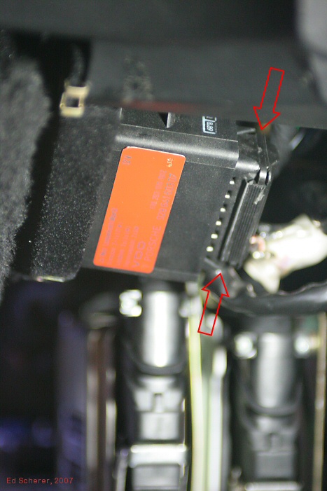
First, here's the lamp control module, after the carpeted piece of trim held on by three Phillips screws has been removed (this is under the dash between the central electric panel and the right-side door, above the LH and EZK modules). You'll want to yank that connector off; it'll probably require a little effort, as it's on there pretty tightly. There are no interlocks; it's just tight. BTW, you don't need to remove the bulb control unit, you just need to unplug the cable.
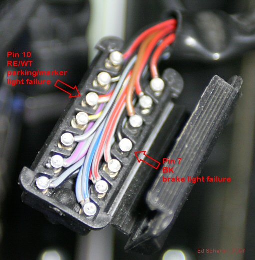
Once you have the cable unplugged, use some flat, wide-bladed tool like a putty knife or wood chisel (I used a 3/4-inch wide wood chisel) and pry open the connector along the long edge that isn't hinged; it'll open up, revealing the pins soldered to the wires as shown in the next photo. Be careful when you open this up, because some of the wires and pins might immediately pull out. Cover them with your thumb or something so they don't pop out!
Use your needle-nose pliers to pull out pin 10 (RE/WT wire) to prevent the parking/marker light failure signal from reaching the pod and pull out pin 7 (BK wire) to prevent the brake light failure signal from reaching the pod. Pull them well back and snap the connector shut again, being careful that all the pins are pushed in again (visually confirm this by looking into the pin holes once the connector is closed again; I had two pins that didn't seat properly the first time I did this, and I had to open it up again and fix that).
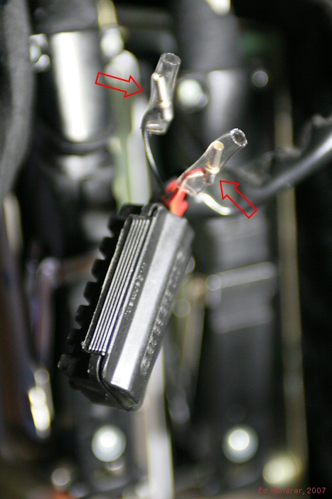
I then used some clear heat-shrinkable tubing to insulate the pins that I removed from the connector, as shown here.
Reattach the connector to the bulb control module. Test that the bulb control module is working to your satisfaction. Then refasten the carpeted trim piece. You're done. Sleep easily, knowing that you can easily reverse this sometime in the future if you need to.
But... one timely thing that I'd like to add now is that the last thing I did last night was to defeat the bulb control module (mine is a 928.641.603.07 on a '90 S4) using a very easy, non-destructive, perfectly reversible technique. You can probably do this in 30 minutes or so. All you need before you begin is:
- a Phillips screwdriver to remove the three screws holding the carpeted trim piece that, when removed, gives you access to the bulb control module;
- a wide wood chisel or putty knife that you can use to pry open the connector to the bulb control module;
- needle-nose pliers, to make it very easy to pull out a couple of pins from the connector;
- some heat-shrinkable tubing about the size of a drinking straw, to cover the pins after you've removed them
I'll provide some explanation along with photos.
First, here's the lamp control module, after the carpeted piece of trim held on by three Phillips screws has been removed (this is under the dash between the central electric panel and the right-side door, above the LH and EZK modules). You'll want to yank that connector off; it'll probably require a little effort, as it's on there pretty tightly. There are no interlocks; it's just tight. BTW, you don't need to remove the bulb control unit, you just need to unplug the cable.
Once you have the cable unplugged, use some flat, wide-bladed tool like a putty knife or wood chisel (I used a 3/4-inch wide wood chisel) and pry open the connector along the long edge that isn't hinged; it'll open up, revealing the pins soldered to the wires as shown in the next photo. Be careful when you open this up, because some of the wires and pins might immediately pull out. Cover them with your thumb or something so they don't pop out!
Use your needle-nose pliers to pull out pin 10 (RE/WT wire) to prevent the parking/marker light failure signal from reaching the pod and pull out pin 7 (BK wire) to prevent the brake light failure signal from reaching the pod. Pull them well back and snap the connector shut again, being careful that all the pins are pushed in again (visually confirm this by looking into the pin holes once the connector is closed again; I had two pins that didn't seat properly the first time I did this, and I had to open it up again and fix that).
I then used some clear heat-shrinkable tubing to insulate the pins that I removed from the connector, as shown here.
Reattach the connector to the bulb control module. Test that the bulb control module is working to your satisfaction. Then refasten the carpeted trim piece. You're done.
Sleep easily, knowing that you can easily reverse this sometime in the future if you need to.Mike
05-21-2020, 10:11 AM
#49
Rennlist Member
I have the same issue with my 78, but I put LEDs in the fog and driving lights. When I turn lights on the warning light comes on. Has anyone fixed this? I'm guessing this wiring is quite different from a '90 S4.
05-21-2020, 01:35 PM
#50
Rennlist Member
you may find this thread useful https://rennlist.com/forums/928-foru...led-bulbs.html
I am not sure if the '78 has the special fog relay, if it does give the swap a try
I am not sure if the '78 has the special fog relay, if it does give the swap a try
05-21-2020, 01:49 PM
#51
Burning Brakes
Yes you can remove two pins from the 12 pin connector at the bulb monitor unit. Pry off the back cover of the connector and remove pin 6 (black wire) and pin 8 (red/white wire). Replace the cover and insulate the now loose pins with heatshrink.

The following users liked this post:
Dundertaker (06-16-2020)
05-21-2020, 03:14 PM
#52
Rennlist Member
Are you sure that it's the Fog/Driving light change to LED is causing that?
To my knowledge, the Lamp Controller only monitors the REAR lights: side markers, Break (and 3rd brake if equipped) and Tail/running lights.
LED issues up front (like a headlight change over to LED) cause a Fog light issues requiring the Fog light relay to be changed over to a standard Type 53.
Dave K9
06-16-2020, 09:11 PM
#53
Instructor
86.5 was getting this warning and this is the fix with full led conversion.