
Interior lights - soft off?
 03-28-2006, 08:08 PM
#31
Rennlist Member
Alan, maybe I'll do some digging around for a relay that will work. I do have empty sockets that could be used but I'd rather save those for possible high-current circuits later. I was not planning to cut any wires. Even on my passing flasher mod, where others might have cut one wire, and stripped and soldered a tap on another, I avoided that. Unless I can figure out where the connector on track 18 is(Post #24 above), and it's easily accessible, I think this will just function with the doors.
 03-28-2006, 11:41 PM
#32
Electron Wrangler
Lifetime Rennlist
Member
Lifetime Rennlist
Member
Dave - I looked at the '78 diagrams - I see what you mean - you have no single point access for all the connections.. tricky! On later models its easier (except for the hatch switch connection straight to ground) since the relay or module output is the only other drive point...
Alan
Alan
 03-29-2006, 12:27 AM
#33
Addict
Rennlist Member
Rennlist Member
Alan,
You lost me at "So I had few minutes to kill at the dr.'s office..."
Andrew, Sprinkle some voodoo shee-hot on that 928 shrine would you,
we gotta get this damn thing done!!
You lost me at "So I had few minutes to kill at the dr.'s office..."
Andrew, Sprinkle some voodoo shee-hot on that 928 shrine would you,
we gotta get this damn thing done!!
03-29-2006, 03:02 PM
#34
Rennlist Member
Justin -- I hope you know I was just returning the favor, yanking your chain. 
Alan -- One of the reasons that I am not jumping at the idea of adding a relay to the CE panel is I've already added one where the seatbelt relay goes -- it's the grey #24 in the pic below, and is a 40A power relay intended to preserve some of the more delicate original pieces that control the AC clutch. I have one remaining empty socket, above it and to the left. After that, I would have to re-wire the neutral safety relay to add another. I'm going to be very careful and choosy about what else I put in there. I hope that 6-pin connector that I mentioned will be easy enough to find, because I would prefer to have this functionality apply to the hatch as well -- but I'm not going to drive myself nuts trying to make it happen. I found a plug & play solution(maybe) that will cost me $30 shipped from Australia. That approach may suit some of the less solder-proficient interested parties. I also have the parts now to build the 2nd diagram above. Actually I couldn't find a dual op-amp so I settled for a quad op-amp. Between the two possibilities I ought to be able to make something happen.
Andrew, Chuck, Justin, this is going to take however long it takes. Again, other priorities... Andrew, you, Patrick and Alan are probably the only ones posting to this thread that will be not able to directly copy my work. It may still be of use to you though. I have a feeling that if this circuit works the way I expect, you could replace the delay relay with a standard(cheaper) relay then graft in the delay/dim circuit.
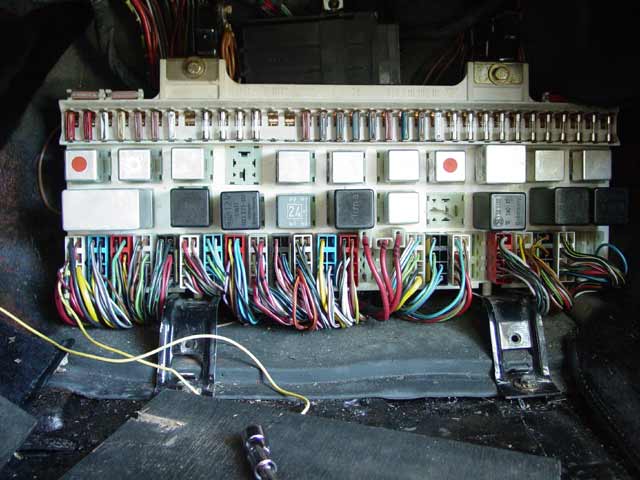
Alan -- One of the reasons that I am not jumping at the idea of adding a relay to the CE panel is I've already added one where the seatbelt relay goes -- it's the grey #24 in the pic below, and is a 40A power relay intended to preserve some of the more delicate original pieces that control the AC clutch. I have one remaining empty socket, above it and to the left. After that, I would have to re-wire the neutral safety relay to add another. I'm going to be very careful and choosy about what else I put in there. I hope that 6-pin connector that I mentioned will be easy enough to find, because I would prefer to have this functionality apply to the hatch as well -- but I'm not going to drive myself nuts trying to make it happen. I found a plug & play solution(maybe) that will cost me $30 shipped from Australia. That approach may suit some of the less solder-proficient interested parties.
I also have the parts now to build the 2nd diagram above. Actually I couldn't find a dual op-amp so I settled for a quad op-amp. Between the two possibilities I ought to be able to make something happen. Andrew, Chuck, Justin, this is going to take however long it takes. Again, other priorities... Andrew, you, Patrick and Alan are probably the only ones posting to this thread that will be not able to directly copy my work. It may still be of use to you though. I have a feeling that if this circuit works the way I expect, you could replace the delay relay with a standard(cheaper) relay then graft in the delay/dim circuit.
Last edited by SharkSkin; 03-29-2006 at 03:24 PM.
 ... Ha!
 03-29-2006, 08:53 PM
#37
Electron Wrangler
Lifetime Rennlist
Member
Lifetime Rennlist
Member
Ah just yanking your chain too - I still have my MT bridge - but if it came down
to it I guess I'd sacrifice it. Won't need to do it for this project on my car but...
I now have no more empty relay sockets after adding a bunch of new functions - so
will need to do it with the next bright idea!
I also don't usually don't like to move or change anything thats original and needed - but
I already eliminated the empty kick down relay socket (had some daisy chained connections
there I needed to preserve)... Seems your 78 panel had no kick-down relay space - direct drive
I guess?
Here is an update to the design I posted that could do a fast dim-up delayed turn off and slower dim down. I haven't built it yet so will need to play with values - then could eliminate the trimmers. It needs a power MOSFET and heatsink - dissipates some power when its dimming.
It could be adapted to dim LED festoon bulb replecements too (much lower power).
Alan
Last edited by Alan; 03-30-2006 at 06:02 PM. Reason: Added part ID's on schematic
03-29-2006, 09:08 PM
#38
Rennlist Member
So where are the door switches in that? Or would I have to adapt some way to get a + signal when those switches close and attach that to the light relay output location shown on your diagram? Not that I blame you for thinking of the solution in terms of later cars -- I was thinking of a solution in terms of earlier cars.
03-29-2006, 09:55 PM
#39
Electron Wrangler
Lifetime Rennlist
Member
Lifetime Rennlist
Member
Dave, just put the door switches where the Relay O/P is (goes low when lights should be on). The idea of this was that its kind of universal - it can be set to have no delay - go straight to dimming (use after the relay) or have a delay as well and use the door switches to drive it.
I assumed parameters should be something like 0.3 second soft ramp to on, ~4-5 second off-delay for the pin switch only mode OR the standard 10-15 seconds off delay for the lock/ignition truncation (via delay Relay) then ~5 second for the fade out - I think this circuit can do all those..
Alan
I assumed parameters should be something like 0.3 second soft ramp to on, ~4-5 second off-delay for the pin switch only mode OR the standard 10-15 seconds off delay for the lock/ignition truncation (via delay Relay) then ~5 second for the fade out - I think this circuit can do all those..
Alan
03-29-2006, 11:49 PM
#40
Rennlist Member
Hmmm... interesting setup. Somehow, I had the idea that the relay output a high signal... that's what I get for not looking, but time is at a premium nowdays. I assume the cap is electrolytic, "-" to ground. If you could come up with some likely part numbers for the 5 semiconductor components I'd be happy to try it. For the MOSFET I could probably get away with a TO-220 package, but later cars may need a TO-3 with all the bulbs you'd be dimming. In fact, I might as well go with the TO-3 since I may eventually add more lights.
03-30-2006, 11:54 AM
#42
Electron Wrangler
Lifetime Rennlist
Member
Lifetime Rennlist
Member
Dave I updated the schematic with part #'s.
the Diodes & PNP transistor is not critical - almost anything will do.
The MOSFET must be N-Channel Enhancement Mode - this one is
a TO220 it needs a heatsink. You need a low on resistance version
this one is 0.08 ohms - this keeps dissipation down when on but not
dimming...
Have at it - I'll try it out too maybe this weekend...
Alan
03-30-2006, 05:54 PM
#44
Electron Wrangler
Lifetime Rennlist
Member
Lifetime Rennlist
Member
Dave yes 4K7 = 4.7K I thought that was pretty universal? (maybe its a European thing) Its just more readable than having to determine a "."
I'm not sure you will find many MOSFET's in TO3 cans... a TO220 with a decent heatsink should be fine.
Dissipation when on should be <2W (for 60W of int. lighting). When dimming it may rise to ~20W peak but only for a few seconds (transient) per cycle.
Alan
I'm not sure you will find many MOSFET's in TO3 cans... a TO220 with a decent heatsink should be fine.
Dissipation when on should be <2W (for 60W of int. lighting). When dimming it may rise to ~20W peak but only for a few seconds (transient) per cycle.
Alan
03-31-2006, 01:10 AM
#45
Rennlist Member
Thanks Alan. I'm used to seeing the decimal point there... maybe it's a euro thing? Also, on one of those forum pages the guy said the project required two 1K2 resistors. The board seemed to have two 2.2k resistors in the spot he mentioned. Sometimes if I'm not paying attention to where something was authored, I end up interpreting 1,005 as "one thousand and five" when "one and five thousandths" is intended. Damned Euros and their secret codes. ")

Anyway, I should have the FET tomorrow, and I'm pretty sure I have the pots listed. I have a handful of suitable diodes, I'm sure.
Anyway, I should have the FET tomorrow, and I'm pretty sure I have the pots listed. I have a handful of suitable diodes, I'm sure.