
Where can we stiffen a 928 body?
 12-20-2005, 12:47 PM
#16
Rennlist Member
Thread Starter

Great info guys. I do remember that finite analysis. I'm just not sure what to do with it. The hatch creaking is a dead givaway that we have room for improvement. Porsch even seam welds thier GT cars before they put them fully together, and some have said they notice the difference.
 12-20-2005, 01:56 PM
#18
Rennlist Member
Thread Starter
Good idea. Thanks.
12-20-2005, 04:56 PM
#19
Rennlist Member
I always liked the idea of another cross bar at the top of radiator line to stiffen the top of the frame, but there probably isnt much flexing there. Just seems to be a big unsupported area. The creaking noises in my hatch were fixed by fitting a receiver with the plastic liner, but it does show that there is movement back there.
jp 83 Euro S AT 49k
jp 83 Euro S AT 49k
12-20-2005, 07:13 PM
#21
Rennlist Member
yep, and mark's car is not much faster than it was before all the fancy tubes. what it does, is put the chassis tuning exclusively on the suspension , where is should be. the stcok chassis is plenty stiff, and with a cage it really stiffens it up . (you will spin one wheel going up incline driveways at an angle , even with LSD!)
part of the handling package is the chassis compliance, and you can do quite well with no stiffening with the 928 for most uses. as soon as you get into racing and you need a cage, a simple one gives you stifness beyond most real race car conversions with bars running everywhere! (ie my buddies, top running M3 racer with PTG style cage with bars EVERYWHERE, is no more stiff than my 928 with only a 6 point simple cage!. actually, when he went crazy on version 2 of the cage, he is now stiffer than the 928 with a simple cage. )
Mk
12-20-2005, 07:20 PM
#22
Inventor
Rennlist Member
Rennlist Member
Originally Posted by EB338
be sure to rust/corrosion coat the places where you put the expanded foam, it will trap moisture, etc and eat the body from within, I have seen it done
12-21-2005, 10:54 AM
#23
Rennlist Member
Sorry, i should clarify. Do NOT use something like great stuff. It will trap moisture and could cause rust. There are several types of expanding foam that need water to set. You actually have to spray the cavity with a little water or it wont expand. This kind of foam, when applied properly, consumes all the water, and will create such a tight seal, that it will protect against further water absorbsion. It is similar to that heat activated expanding foam on the ford f150 commercial, but is water activiated.
Hans
Hans
12-21-2005, 11:10 AM
#24
Rennlist Member
Originally Posted by SharkSkin
Brendan,
There was a thread awhile back where someone had done a finite element analysis with lots of cool diagrams, and a rennlister had bumped into the info and posted a link. Whatever the accuracy or applicability for you, it's interesting stuff. Thread here.
There was a thread awhile back where someone had done a finite element analysis with lots of cool diagrams, and a rennlister had bumped into the info and posted a link. Whatever the accuracy or applicability for you, it's interesting stuff. Thread here.
Finite Element Analysis is far from being a perfected means of determining microstrain to any given part. I deal with this stuff daily, at present time it is still no match for actual strain gage testing with a wheatestone bridge. MOST of the time Finite Element Analysis will come up with more than a few theoretically high strain areas where strain is actually minimal and it will also miss areas that actually have high levels of strain.
At present Finite Element Analysis is FAR from being more than a supplemental tool for determining field stress. It will definitely play a bigger role in the future though, for now strain gages can't be beat.
12-21-2005, 11:44 AM
#25
Nordschleife Master
Ben's comments are generally correct. With a well defined part and forces the results are very good. If there's a mistake in either, the the results are not valuable. I was talking about this with my dad the other day and he brought up a story where a junior engineer had modelled a part and it was failing at 15% of the predicted loads. The graphs were pretty but the external forces had been modelled wrong. Oops.
Also reminds me of some work I did in mechanical testing. We were making equipment to test aircraft airframes. Up to 100 hydraulic actuators bending a full-scale prototype with up to 2000 strain gauges mounted to it. The complete model had been done in CAD and FE analysis but they still needed the hard data. An interesting step was that the data from the model was compared to the acutal measurements in during the testing. This would identify places where the stresses were unexpected and halt testing.
Anyways, back to the topic at hand: I like the pics and the analysis the paper gives. They're looking at a very important aspect of body stiffness in searching for higher harmonic frequencies for the body in torsion. Looked at from a practical perspective, if you hit a pothole with one wheel, what does the frame of the car do?
A big failing of the model is that only the body itself is considered. There is no engine, drivetrain, glass, hatch or front sheetmetal. Also, The options of the analysis were limited to reinforcing existing body members and not adding new parts.
Looking at the results (albiet quickly) there are some clues for our needs. First off it says to reinforce between the shock mounts. It's already be noted that the tranny cradle provides this.
Another is the need to stiffen the "A" pillars alongside the windshield. This would be hard to do and keep nice looking.
One suggested thing that we could do is to reinforce the triangles alongside the engine walls which extend out front the corners of the windshield. (If youve ever seen a 928 with the fenders off these parts would be clear.) This givem me the idea to add another piece underneath. This would be (roughly) triangular as well but at about a 45 degree angle to the top triangle and the wall of the engine comparment. This would interfere with the washer tank (right) and cruise control (left) but would really stiffen the front of the car. I'm wondering about getting the fender on as well, but the opportunity is there.
Last edited by GlenL; 12-21-2005 at 12:05 PM.
12-21-2005, 01:22 PM
#26
Rennlist Member
Thread Starter
This Triangle you are talking about:
Where would you go with the support?
On the subject of the front cross member - there is ALOT of movment there when the car is on its suspension. And Porsche knew this as they added those little angle irons from the K-member to the back of the front A arm bolts.

Where would you go with the support?
On the subject of the front cross member - there is ALOT of movment there when the car is on its suspension. And Porsche knew this as they added those little angle irons from the K-member to the back of the front A arm bolts.
12-21-2005, 01:25 PM
#27
Rennlist Member
Originally Posted by 928drvr86.5
Finite Element Analysis is far from being a perfected means of determining microstrain to any given part. I deal with this stuff daily, at present time it is still no match for actual strain gage testing with a wheatestone bridge. MOST of the time Finite Element Analysis will come up with more than a few theoretically high strain areas where strain is actually minimal and it will also miss areas that actually have high levels of strain.
At present Finite Element Analysis is FAR from being more than a supplemental tool for determining field stress. It will definitely play a bigger role in the future though, for now strain gages can't be beat.
At present Finite Element Analysis is FAR from being more than a supplemental tool for determining field stress. It will definitely play a bigger role in the future though, for now strain gages can't be beat.
12-21-2005, 03:47 PM
#28
Nordschleife Master
Originally Posted by BrendanC
This Triangle you are talking about: Where would you go with the support?
If the new piece was welded to the firewall of the passenger section it'd give a lot more stiffness. However, that'd interfere with how the fender mounts to the firewall. Some modding of the fender could be done.
Thinking about the torsional rigidity of the frame in the front, if a "X" could be put in it'd really stiffen the front. Maybe ahead of the radiator it'd work. Fron the corners of the lower crossmember (below rad) to the corners of the upper (latch mounting). I'm not certain what mechanical bits (Headlight bar?) would be in the way. Nothing that's needed on a track car, I'd venture.
Now that I'm thinking about it, I'd like to have some work done myself. Hhhmmmm....
12-21-2005, 04:28 PM
#29
Inventor
Rennlist Member
Rennlist Member
I would look for where the 'intelligent designer' put crumple features*, like ribbing or understrength areas. Then strengthen via plates or framing.
...
Here's a pic I saved from that thread, which I can't seem to locate via search:
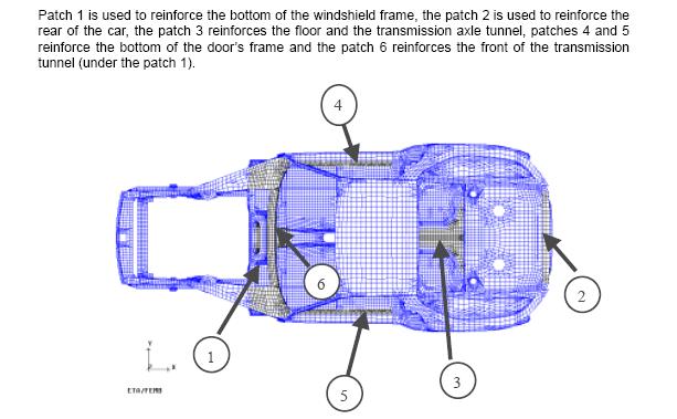
*Seems to me, safety features, and access would be the only comprise of rigidity for a car of this caliber.
...
Here's a pic I saved from that thread, which I can't seem to locate via search:
*Seems to me, safety features, and access would be the only comprise of rigidity for a car of this caliber.
