When you click on links to various merchants on this site and make a purchase, this can result in this site earning a commission. Affiliate programs and affiliations include, but are not limited to, the eBay Partner Network.
It looks like I might be back in the saddle again with one of these early Andy Keel SC kits. Darien contacted me again with an issue he has with his installation and that is that with the original kit (and as can be seen in a couple of the very early pictures of one of these kits) the PS pully provided with the kit is a bit larger than the original pully. I find that the original PS pump pully is either 4 1/4 inch in diameter or about 3 3/4 inch. The one supplied with the SC kit is about 5 inches, and apparently it caused the SC belt to rub on the alternator. The cure was apparently to remove the third/rear SC mounting bolt and then rotate the SC up a bit and then rely on just the other two mounting/adjustment bolts. That was apparently not desirable to some, so there is a cure for that and that has been to make and install a little idler that can lift the belt from it's back up off the alternator.
Darien inquired if I might be able to make him one of the idlers and he sent me a couple of pictures of some other guy's. I studied the pictures some and then designed, in my head, of course, a similar idler, but it was going to be bit complex to make, probably involving having the body or basis for it waterjet cut which would save me a lot of machine work.
Then it finally occurred to me to go back and consider why the idler was needed in the first place; and that is because of the larger SC pully included in the kit. Then, upon looking at the pictures of the Pully provided by Darien I can see that what Andy did was simply find a pully off the shelf that was close and could be included in the kit rather than having to make one that is the correct size. So, I decided that the best thing to do would be to make the correct pully; and that will be much simpler than designing and fabricating the idler.
So that is where I am with this. I have some material already and have decided to go with the smaller diameter pully found on some of my PS pumps, 3 3/4 inch, and make it in a 4 groove design to match the Micro-V belt; and all I need now is to figure out how to order one of the groove lathe bits from China to turn the grooves with. I have found at least two places there online that have the tool but for the life of me I cannot find out how to order anything from them.
Last edited by Jerry Feather; 10-22-2023 at 07:20 PM.
Jerry,
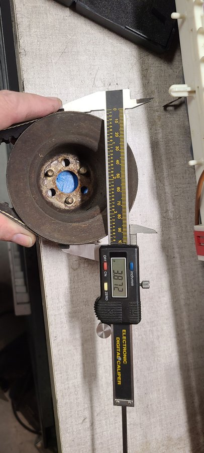
Just wanted to follow up with a little more detail on the pulley sizing that you were discussing with Darien. I finally remembered where I put my take-off factory PS pulley so thought I'd get you some real numbers to work with.
I understand that the actual diameters are effectively at the midline of the belt, so these numbers could be manipulated just slightly since I was measuring to the outside of the V-belt on the factory pulleys, and I measured the TS pulleys without a belt installed, I however think that these are probably good enough for discussion purposes.
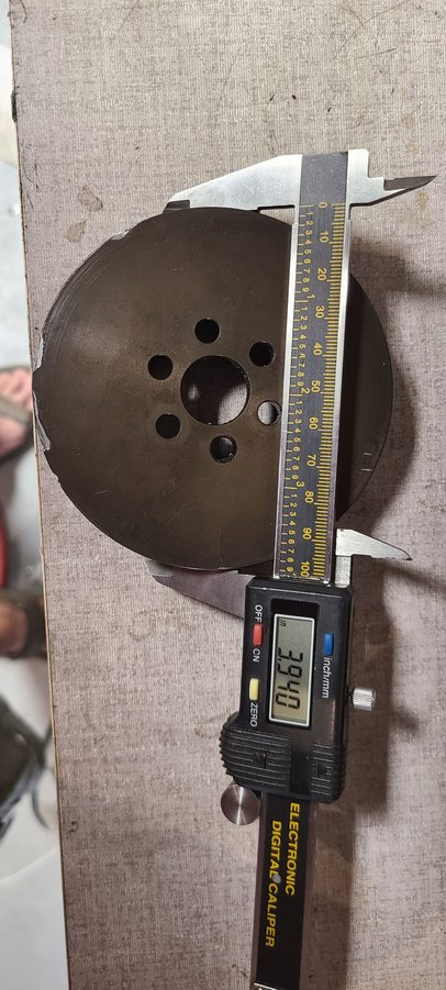
Below is a table I put together really quickly that shows the diameters as measured of each pulley and the resulting drive ratio of the PS Pump and relative overdrive percent of the different configurations. I randomly chose a reduction of 0.25" radius reduction to gain clearance (0.50" diameter) for the straight belt run with all three bolt in the PS Pump Carriage. I have not actually determined if this is the appropriate resizing needed to keep the belt from rubbing, but used to illustrate the pump drive ratio effects.
Stock Diameter Ratio Drive%
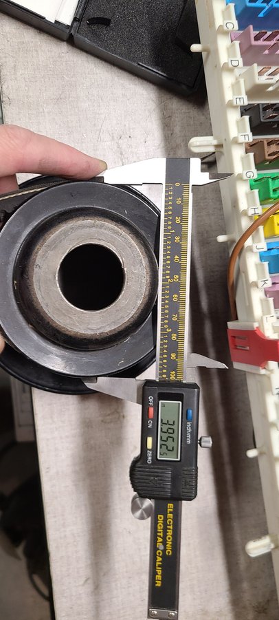
Crank 3.952 1.02 100%
PS 3.872
TwinScrew Diameter Ratio Drive%
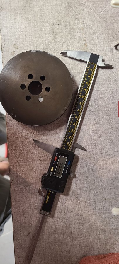
Crank 4.959 1.26 123%
PS 3.94
As you can see the TS pulleys are already pushing the PS Pump to about a 25% overdrive, so I am reluctant to increase the pump speed much further that the current ratio.
In my opinion the increased diameter of the crank pulley is the primary driver for the clearance issue, and I'm not sure that I would try to compensate by decreasing the PS Pump pulley any further.
I made a fairly simple idler assembly for mine and retained all three mounting bolts. I'm sure that could be better executions but I just made it out of random stuff I had readily available at the time.
I"ll do a little digging and see if I can come up with any picks of my idler and post them if I do.
Maybe not the best of pictures, but should give you a good idea of my method. Basically, I removed the two inboard mounting bolts for the PS Pump Carriage. Then made a bracket that bridged the tensioner and picked up both the factory bolt locations. In the pic it looks like a plate with spacers, but in actuality it is all one piece I machined out of a chunk of aluminum. The areas that look like spacers is machined to match the diameter of the original washers under the factory bolt heads. I ended up countersinking the upper bolt head location to make sure it cleared the idler and belt. If using a smaller diameter pulley this may not be necessary. I then installed the bracket with the appropriate length counter sunk bolt in the upper hole, and increased the bottom bolt to pass through the pulley and bracket. for assembly, I just bring the bolts up to remove any clearance in the bracket assembly then use the factory bolt to tension the belt, and finally torque the three bolts on the carriage, the two replacements that pass through the idler and bracket and the third outboard bolt which was traditionally removed during the initial installation of the TS kits.
Thanks, Simon, for your very thoughtful analysis of this situation for Darien. The one difference with his is that the PS pully with his case is 5 inches rather than 4, and that appears to be what allows the belt to rub on the alternator bolt. I don't know what size his crank pully is but even at an inch over the original that would put the belt near the PS pump at only a small fraction closer than intended, and probably no enough to require an idler at least with the 4 inch PS pully.
As to running the PS pump at higher RPMs I don't have any data or information about just how fast it can be run. It functions quite well at 700 to 6000 engine rpm as it is, so I have no way of knowing it there is a limit to it's speed. I think we can say that with changes in the pully sizes we will be increasing the pump speed, but that does not lead to it being overdriven.
Thanks again, Simon.
Last edited by Jerry Feather; 11-05-2023 at 10:24 AM.
We may need to confirm with Darien, but I'm pretty sure his pulleys are identical to mine.
I did, and he measured his PS pully while we were on the phone and it is 5 inched in diameter.
EDIT: Now I'm not sure what with or how he is measuring it because I measured his pully myself with my caliper on my computer screen by measuring the diameter and the distance between two bolt hole centers, then I measured the bolt holes on one of my pumps, and by calculation of the ratios I find that his PS Pully is 4.17 inches in diameter. That is just about the same as the diameter of the flat pully on some of my pumps, but a bit larger than the cup style of offset pulleys on the other ones, which roughly measure a bit under 4 inches.
Last edited by Jerry Feather; 10-31-2023 at 11:53 AM.
It looks to me like I am back to designing an idler for Darien. I think I'll make one out of the material that I had bought to make a smaller pully, that now appears to not be the problem. I've got to get the bolt sizes and the spacing for the idler and then I can work one up.
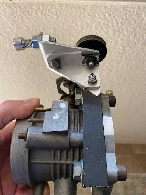
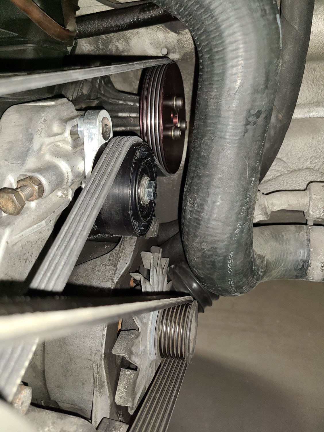
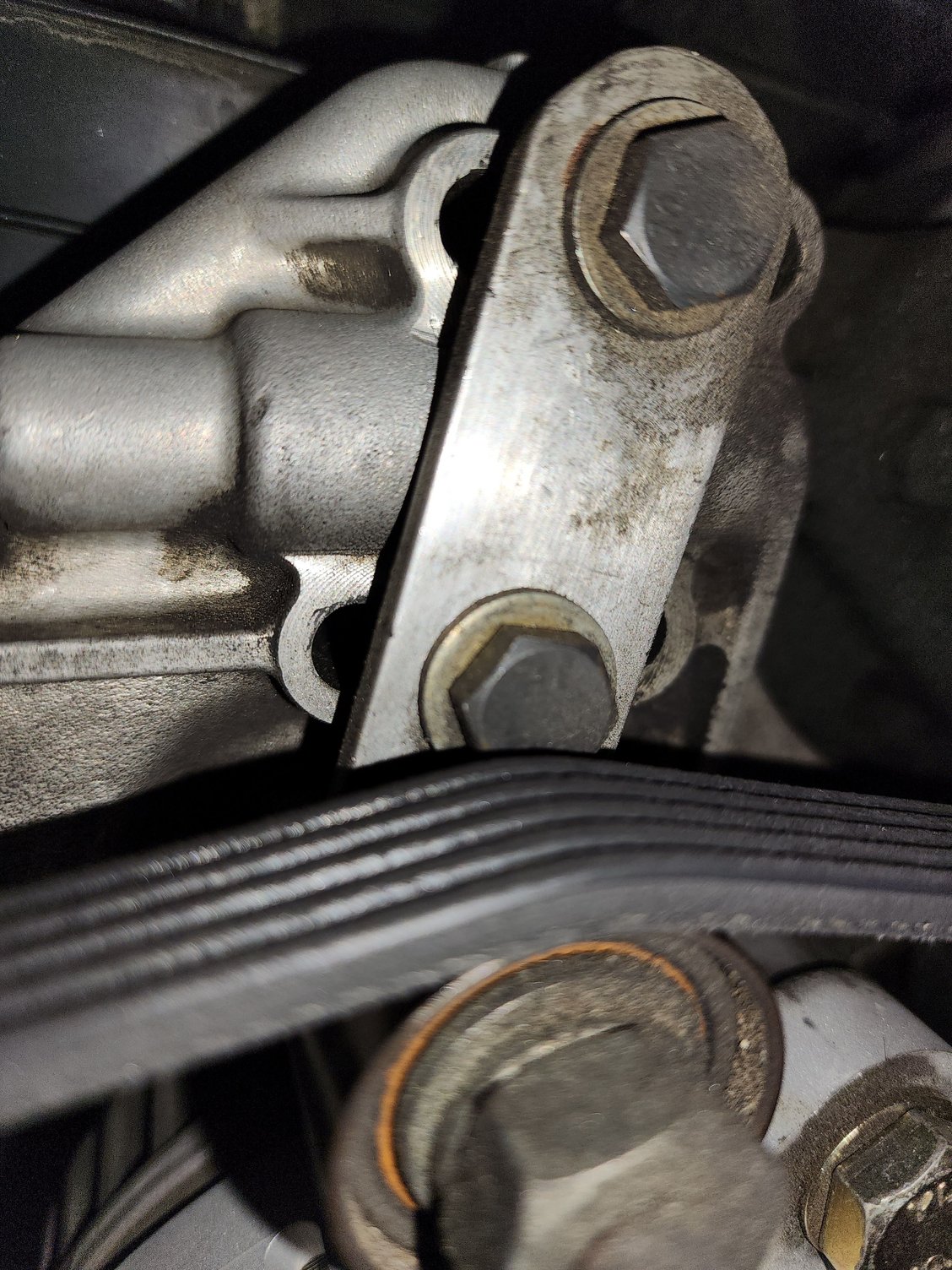
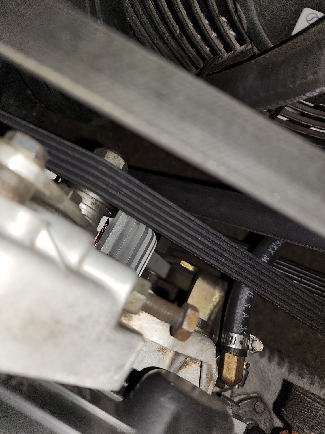
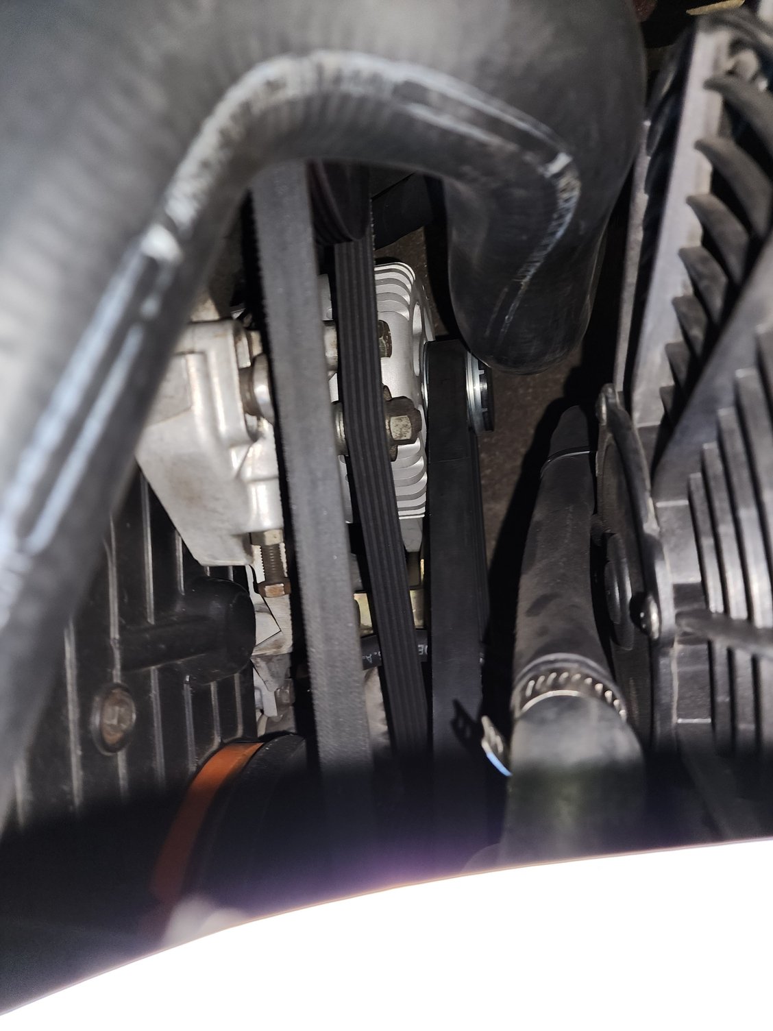
Darien had asked my a few weeks back to shoot him some pic's of my current setup, it's been working for years w/o issue, just a simple bar stock and some spacers/washers for clearance and a small roller.
Just got the car back home from storage hope this helps.
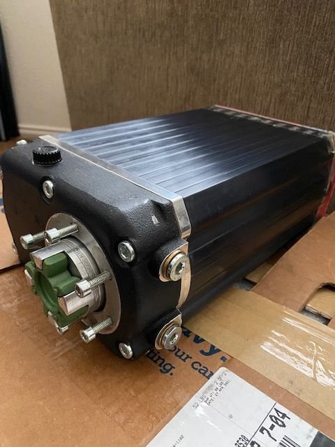
After a lot of healing time after losing Rocket and selling the Louie Ott beast; I started to have withdrawals driving the 89 S4 5spd normally aspirated. So, I put the word out that I was looking for another Andy Keel kit and Lex contacted me about his! Although I had to pry from his grasps, he sold me his Inter-cooled (IC) Keel kit with a brand (new still in the wrapper) 2.2L Autorotor Twinscrew and parts powder coated
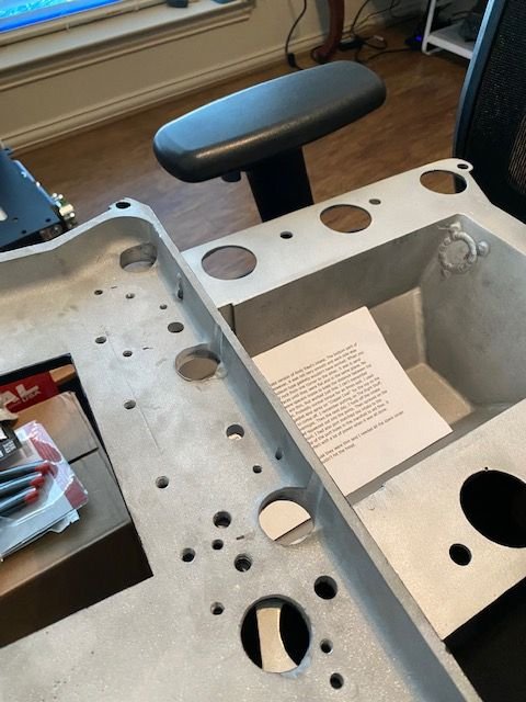
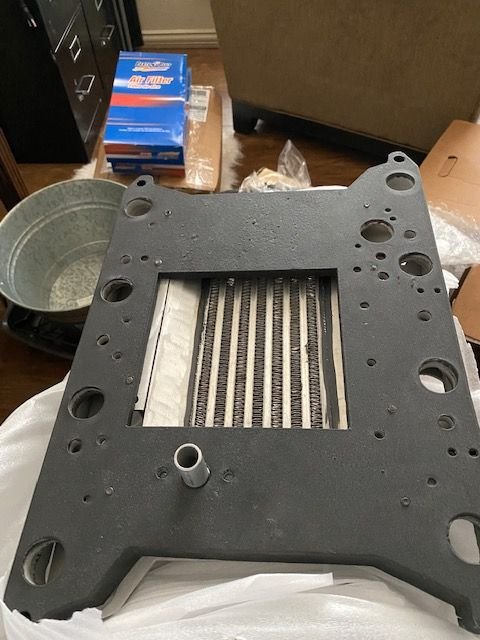
Unfortunately 2021 was a very busy year so it took longer than I wanted to get installed, but it allowed me to take my time and sort some issues out. This kit came with an SC mounting adaptor plate which is awesome considering the SC kit I had on Rocket the SC was hard mounted to the manifold. The problem I found with the adaptor plate is it was too thick and would cause the SC to sit too high. I was able to source a thinner but same heat resistant rigid sheet metal and it worked like a champ!
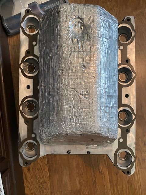
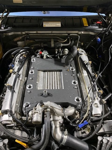
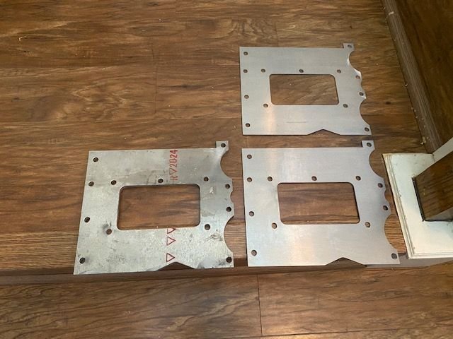
The IC mounting plates had some flaws that needed to be addressed (cracks, spacing). Had a local shop repair and filled any voids Also, the SC manifold gaskets had to be extra thin so I got a set of 944 S gaskets to try but chose not to use because they didn't line up (See pic). I ended up getting a tough gasket material and cut to fit.
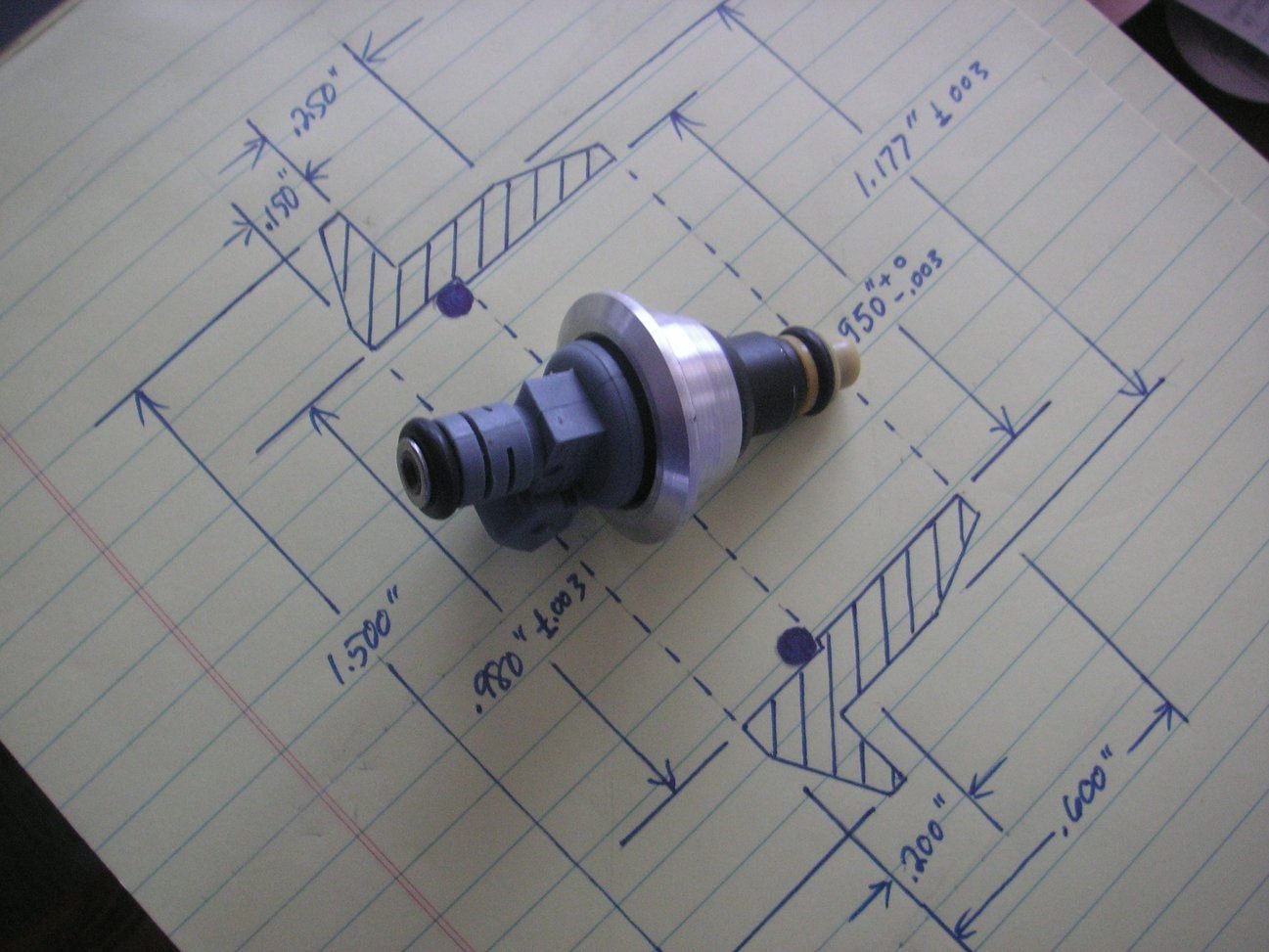
Jerry Feather saved the day when he offered to make a set of Injector Bushings...Much appreciated Jerry!!
Simon modified Bill ***** throttle cable roller braket and it came out beautiful...thanks Simon!!
I was finally able to start the intsallation around the holiday break...here are some test fitting and adjustments!
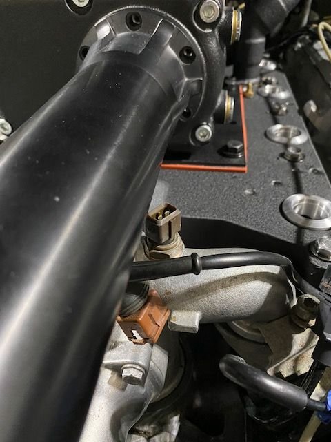
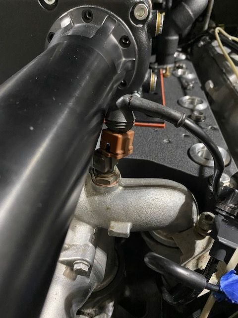
I discovered that the alignment of the snout would interfere with the water bridge coolant temp sensor. I ended up modiying the connector to reduce the height and all good.
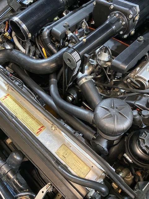
Simon's handy work on the copper tubing used for the Oil Breather set-up...thanks again Simon!!
I used the most convenient location to place the Provent and it seems to be fine for now.
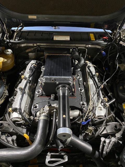
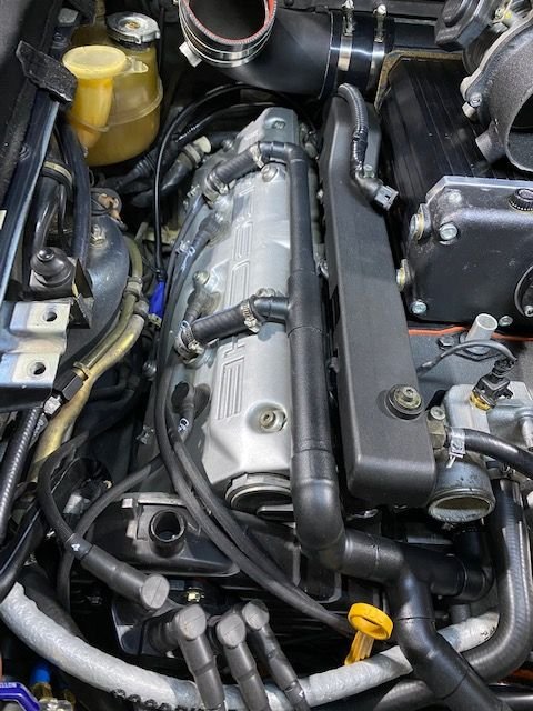
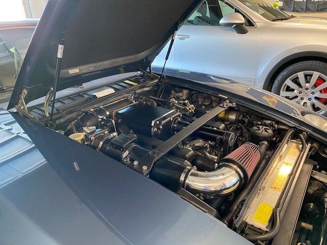
FINALLY...COMPLTED the INSTALL... the intake routing may be temporary as I ran the intake into the passenger fender on Rocket and it's a lot cooler and easier on the eyes
Now...once I get time and Bill Ball is available we'll begin Sharktuning!! Still need to route the IC hoses and modify the windshield washer reservoir but it's winter temps in Texas...SO GLAD TO HAVE ANOTHER SUPERMODEL
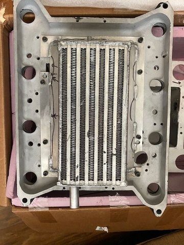
I am following the same route with the intercooler mounted underneath. My question is how you made the mounting plate and what intercooler you used?
Would be great if someone had a cad file for it so I could machine one up locally
Darien had asked my a few weeks back to shoot him some pic's of my current setup, it's been working for years w/o issue, just a simple bar stock and some spacers/washers for clearance and a small roller.
Just got the car back home from storage hope this helps.
I agree this in not that complicated to create. A simple bar with a couple spacers under it is really all that's needed. The only thing of semi-precision is drilling the holes the correct distance apart. For mine I didn't even extend it for the 3rd hole, I simply put a long enough bolt in the lower bracket position to pass through the idler pulley, bracket and tensioner.
mine isnt very accessible in my installation, so it may be easier to have Darien, or someone else measure the bolt spacing, then all that should be necessary is to drill two 8mm holes at that spacing in the bar, provide two spacer washers (for the bar to clear the tensioner), longer bolts and a pulley.
Now that I am focused again on the idler I have one pretty much designed for Darien. I like the approach to this that involves putting the idler pully on the bottom bolt of the tensioner, but what I don't like about it is that the only idler pulleys I can find are pretty large and result in offsetting the belt way more than is needed. That is probably no technical problem in respect to the system operation, but it just doesn't set well with me.
I have found an idler pully that is 2 inches in diameter and that is just about the smallest I have found so far. I think I am going to make the body of the idler out of the same material that I had bought to make the pully, and that is 3/4 inch aluminum. I'll drill the two mounting holes where they go ,when I can find the exact distance from center to center, and then mill a kind of trough in the back to clear the hump in between the bolts, rather than putting spacers behind it, and then I'll drop down about an inch and offset to the left about that much, or a bit more, and mount the 2 inch idler pully with some spacers behind it to line the pully up with the belt. I'm going to drill and tap the 3/4 inch thick aluminum for the pully and then provide for a locking nut on the back end of the bolt after it is tightened.
Last edited by Jerry Feather; 11-18-2023 at 11:47 AM.
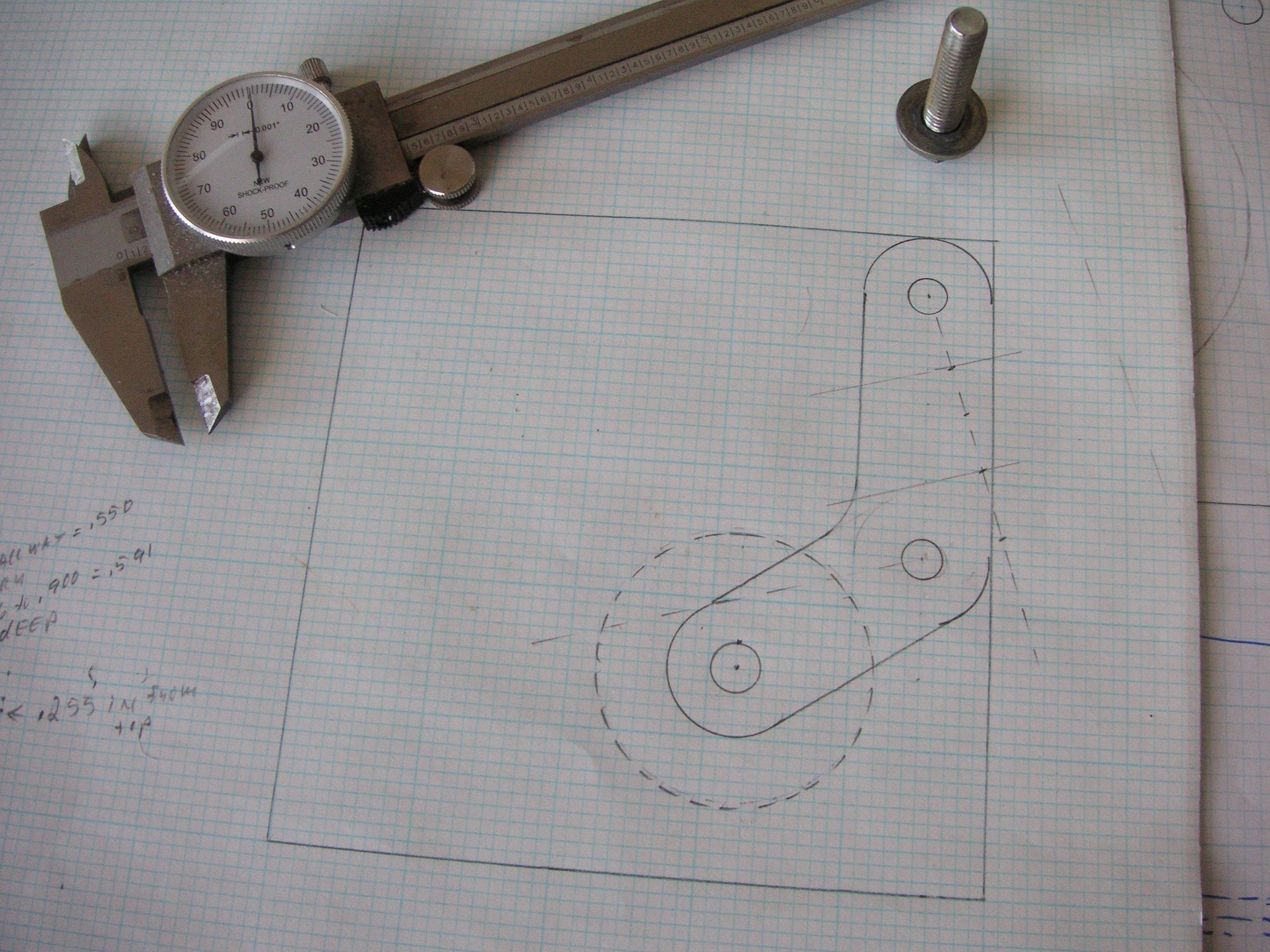
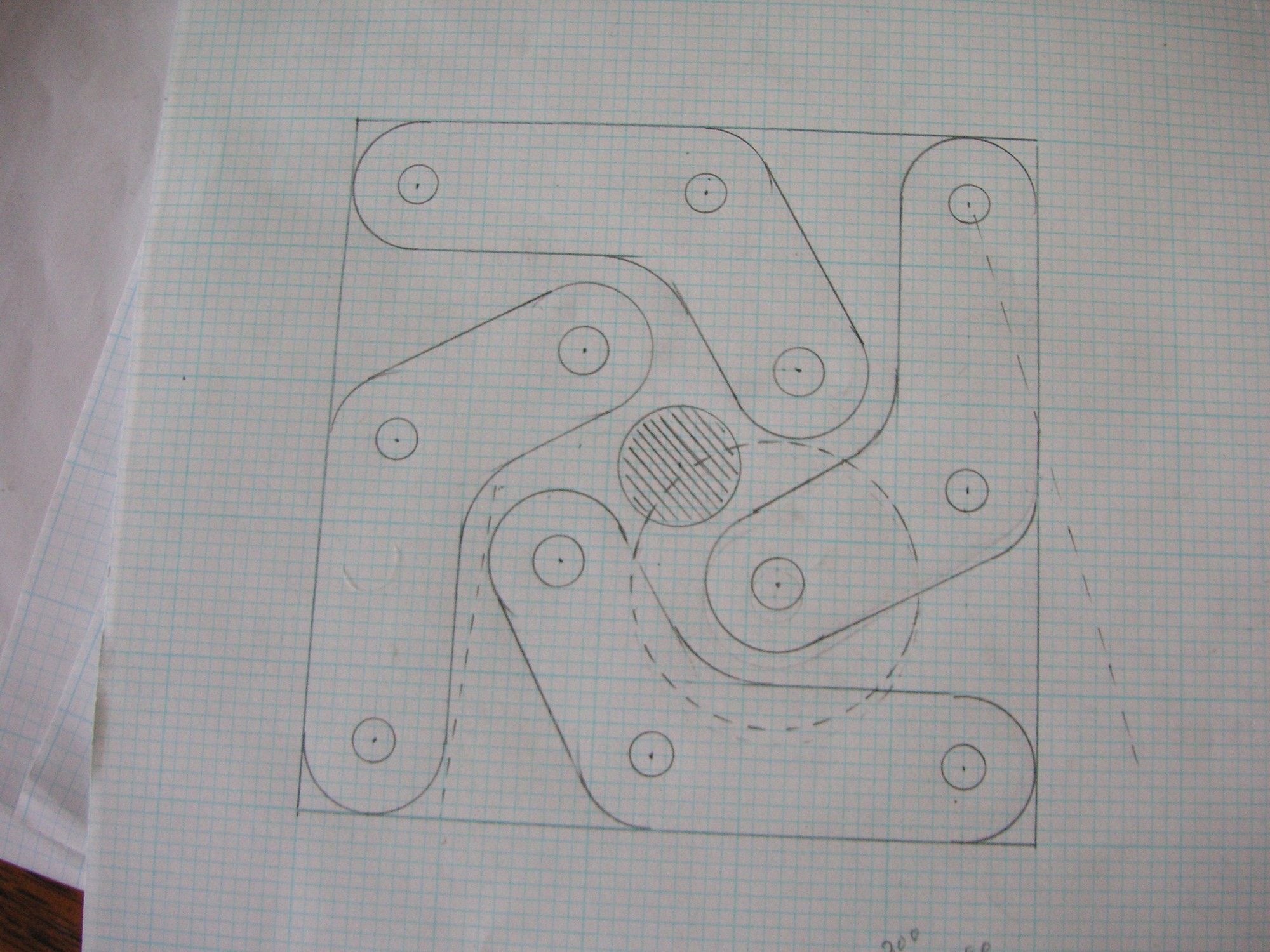
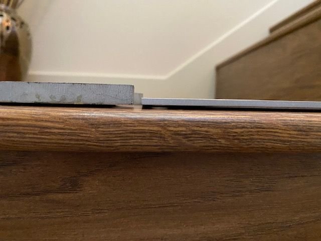
I have found the distance between the tensioner mounting bolts and have drawn up my design of the idler base to fit. One discrepancy I have found is that The area that the bolts holding the front of the tensioner are not on the same plane. They differ by about 80 thou. That means that in order to mount the idler base the surfaces must be put on the same plane. That can be done on an individual basis by careful milling of the idler base, but I suspect that the differences in the bolt bases are probably all across the board. That is going to probably require a system of shims to level out the idler in individual cases, at least on one side or the other. I had wanted to do my idler base without using shims, but I think I am stuck with some.
Here are a couple of drawings of my design. I designed one and then found that if I modified it a tiny bit I can actually get 4 of them out of one piece of 5 by 5, 3/4 inch aluminum plate.
Last edited by Jerry Feather; 11-10-2023 at 11:09 AM.
I think what you have designed there looks very good, but am wondering if there is any significant benefit to adding the extended leg for the idler pulley to mount to as opposed to just locating it on the lower bolt? looking at your first drawing I see several lines that I assume are showing the orientation of the mount bolts relative to vertical and assuming the one off the lower mount bolt going left is the orthogonal or horizontal plane.
If the assumptions above are correct and based on the second drawing you are only gaining about 0.3 inches of vertical drop of the pulley location with the added arm. If you couple this with the angle of the belt run off the bottom of the PS pulley to the bottom of the crank pulley, I suspect that you will essentially null out any benefit of dropping the pulley as you move it toward the center-line of the car.
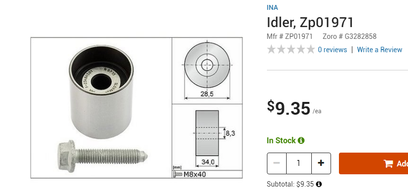
Like you I think the best solution would be to use a smaller diameter pulley. I ended up with the pulley I'm running because I had it left over from a serpentine belt change on our Cayenne, but if I'd had to source one I would probably look for some thing more in line with the one below. If you went that route, and still wanted to run the offset arm for the roller location you should be able to significantly lower the arm position without it interfering with the alternator to significantly straighten the belt run over the idler.


 10-22-2023, 01:32 PM


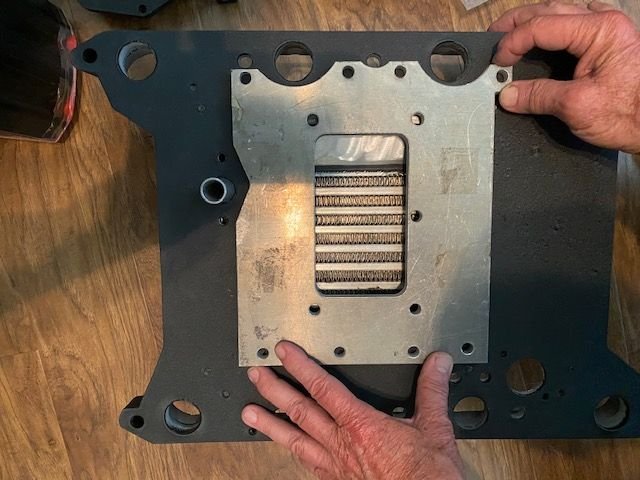
 Also, the SC manifold gaskets had to be extra thin so I got a set of 944 S gaskets to try but chose not to use because they didn't line up (See pic). I ended up getting a tough gasket material and cut to fit.