

H5 to H4 conversion with electric adjusters
 01-24-2012, 03:34 PM
#91
Rest in Peace
Rennlist Member
Rennlist Member
Join Date: May 2006
Location: Bird lover in Sharpsburg
Posts: 9,903
Likes: 0
Received 2 Likes
on
2 Posts
Well crap, back to square one, it looks like the swivel frame is different on a 90 or up.
Crap.
So this is on the back burner until I can get the rest of the parts I need.
EDIT, looks like I spoke too soon, they are the same part number, not sure exactly why I could not get them to fit.
More problems, oh well
Crap.
So this is on the back burner until I can get the rest of the parts I need.
EDIT, looks like I spoke too soon, they are the same part number, not sure exactly why I could not get them to fit.
More problems, oh well
Last edited by blown 87; 01-24-2012 at 06:20 PM.
 01-24-2012, 04:51 PM
#92
Advanced

Join Date: Feb 2007
Posts: 60
Likes: 0
Received 0 Likes
on
0 Posts
I'm using (per Alan's suggestion) 80/100 watts in my H's with the low/high beam filaments on at the same time when high beam is selected only.
01-24-2012, 05:09 PM
#93
Rest in Peace
Rennlist Member
Rennlist Member
Join Date: May 2006
Location: Bird lover in Sharpsburg
Posts: 9,903
Likes: 0
Received 2 Likes
on
2 Posts
I think that is what Alan told me.
That will be easy to do with when you relay the lights, just take the switched side of the high beam relay into the hold in coil of the lows.
01-24-2012, 05:31 PM
#94
Electron Wrangler
Lifetime Rennlist
Member
Lifetime Rennlist
Member
Thread Starter
To do high & low on together - you must use local relays (per side - 4 relays total):
Alan
01-29-2012, 12:18 PM
#95
Rennlist Member
First, THANK YOU Alan for all the information in this thread. I'm done, finally, hit a couple of speed bumps but all is good.
We got a pair of adjuster-motors from DR last year, at his charity auction at SITM. (I had to out-bid Sue to get them). Then Greg's thread, plus long dark nights and too many deer this time of year, provide inspiration to get it done. (Greg's thread is now combined here, starting with this post).
I got most of the parts from Roger, but the first wrinkle was that the new-style ***** (928 631 148 00, to fit the potentiometer) were NLA. Used parts were also scarce, so Roger sent an early-style **** (928 631 221 01) for the hydraulic adjuster to see if it could work. The mounting was nothing like the new part but I finally made it work by digging out the molded plastic insert, machined a new delrin insert to fit the pot, figured out how to chuck the rubber **** in a lathe, and then found the right kind of glue to get it all back together.
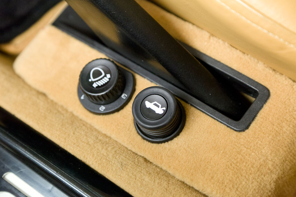
I also made the **** a bit shorter at the direction of the Department of Interior D�cor, the feeling was that the stock **** was a bit too tall. Next time I would probably make it not quite so short, e.g. match the height of the rear-hatch release.
And the 16mm nut specified by PET (900 034 013 02) was way too thick to hide under the **** (at least for my modified ****) so it got made thinner...
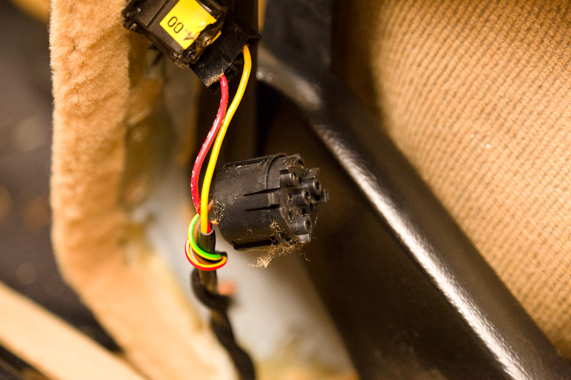
This was a '90, so the driver-side "hump" was pre-wired for the poteniometer (part# 928 613 146 00), plug and pray! For pre-90 cars, the connector is 944 613 531 01 and the contacts are 944 612 548 00 (three req'd).
The next step was mounting the motors, I followed Alan's guide here. I found that leaving the H4's attached to the yokes, and removing them together was easier than removing the H4's first-- that little clip gets in the way.
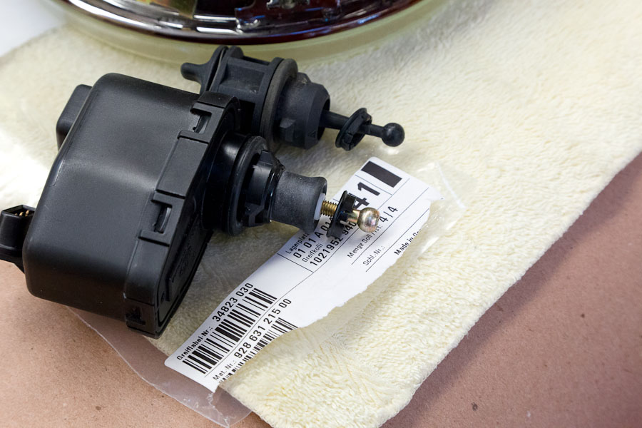
Here's the motors, compared to the fixed struts. The adapter shown in the PET are is not needed, that is used on the fixed strut only. And the motors came with rubber seal rings (at least ours did). The locking clip (928 631 215 00) is the same as the fixed adjuster and can be re-used, but they are cheap and new is good insurance.
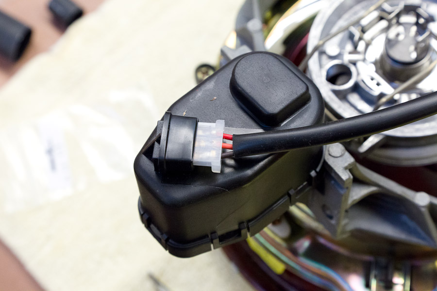
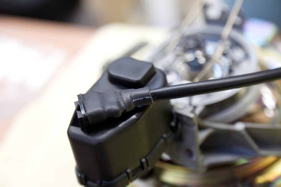
I was able to identify the proper connectors for the motors, the connector housing is (2/ea) 311 906 231B (VW/Audi part# also available through Porsche) and (6/ea) 111 971 958 contacts ditto, and Roger stocks all this stuff now. The boot (022 906 102c) is NLA, and the cross-reference doesn't work so I wound up sealing it with shrink-tubing.
I used the factory harness from the pot to the CE-panel area, to the flat connector that Alan shows in this thread. I haven't found the proper male pins yet but twisted wires shoved into the connector and taped works pretty good
I ran the new harness to the headlights through the firewall above the CE panel and then followed the main harness up the starboard side of the engine bay, past the jump post and then split from there, left and right. That meant drilling a new opening in the firewall, taking care to miss the fuel lines. But I had done that already, to run wires from the laser counter-measures in the front. I looked for Alan's opening into the cowl area on the driver's side but didn't find it, probably didn't dig deep enough... That would be simpler, I think.
And Viola!! It all works! It was certainly more work than I expected, primarily because of the stupid ****, and also getting the wires properly arranged inside each fender, and then discovering that the foal seals on the fender-liners were trash and the PO had used all sorts of hardware-store fasteners for re-assembly
I also fitted relays at the same time, which led to one additional wrinkle which I will describe separately.
Cheers,
We got a pair of adjuster-motors from DR last year, at his charity auction at SITM. (I had to out-bid Sue to get them). Then Greg's thread, plus long dark nights and too many deer this time of year, provide inspiration to get it done. (Greg's thread is now combined here, starting with this post).
I got most of the parts from Roger, but the first wrinkle was that the new-style ***** (928 631 148 00, to fit the potentiometer) were NLA. Used parts were also scarce, so Roger sent an early-style **** (928 631 221 01) for the hydraulic adjuster to see if it could work. The mounting was nothing like the new part but I finally made it work by digging out the molded plastic insert, machined a new delrin insert to fit the pot, figured out how to chuck the rubber **** in a lathe, and then found the right kind of glue to get it all back together.
I also made the **** a bit shorter at the direction of the Department of Interior D�cor, the feeling was that the stock **** was a bit too tall. Next time I would probably make it not quite so short, e.g. match the height of the rear-hatch release.
And the 16mm nut specified by PET (900 034 013 02) was way too thick to hide under the **** (at least for my modified ****) so it got made thinner...
This was a '90, so the driver-side "hump" was pre-wired for the poteniometer (part# 928 613 146 00), plug and pray! For pre-90 cars, the connector is 944 613 531 01 and the contacts are 944 612 548 00 (three req'd).
The next step was mounting the motors, I followed Alan's guide here. I found that leaving the H4's attached to the yokes, and removing them together was easier than removing the H4's first-- that little clip gets in the way.
Here's the motors, compared to the fixed struts. The adapter shown in the PET are is not needed, that is used on the fixed strut only. And the motors came with rubber seal rings (at least ours did). The locking clip (928 631 215 00) is the same as the fixed adjuster and can be re-used, but they are cheap and new is good insurance.
I was able to identify the proper connectors for the motors, the connector housing is (2/ea) 311 906 231B (VW/Audi part# also available through Porsche) and (6/ea) 111 971 958 contacts ditto, and Roger stocks all this stuff now. The boot (022 906 102c) is NLA, and the cross-reference doesn't work so I wound up sealing it with shrink-tubing.
I used the factory harness from the pot to the CE-panel area, to the flat connector that Alan shows in this thread. I haven't found the proper male pins yet but twisted wires shoved into the connector and taped works pretty good
I ran the new harness to the headlights through the firewall above the CE panel and then followed the main harness up the starboard side of the engine bay, past the jump post and then split from there, left and right. That meant drilling a new opening in the firewall, taking care to miss the fuel lines. But I had done that already, to run wires from the laser counter-measures in the front. I looked for Alan's opening into the cowl area on the driver's side but didn't find it, probably didn't dig deep enough... That would be simpler, I think.
And Viola!! It all works! It was certainly more work than I expected, primarily because of the stupid ****, and also getting the wires properly arranged inside each fender, and then discovering that the foal seals on the fender-liners were trash and the PO had used all sorts of hardware-store fasteners for re-assembly
I also fitted relays at the same time, which led to one additional wrinkle which I will describe separately.
Cheers,
01-29-2012, 12:38 PM
#96
Rest in Peace
Rennlist Member
Rennlist Member
Join Date: May 2006
Location: Bird lover in Sharpsburg
Posts: 9,903
Likes: 0
Received 2 Likes
on
2 Posts
Sadly my motors simply are not going to go into the hole in the swivel frame or the part below them, so I am going to have to get some measurements from some one who actually got them to fit.
BTW, Roger sent me some wire ends that sure look like they are going to work.
The other snag is the connector that your car came with, the ones I have got are not the correct ones. (correction, they are the right ones)
But that is to be expected when trying to do things like we are doing on these old cars.
So how do you like them so far?
Last edited by blown 87; 05-13-2012 at 02:35 AM.
01-29-2012, 01:40 PM
#97
Electron Wrangler
Lifetime Rennlist
Member
Lifetime Rennlist
Member
Thread Starter
I will be getting those connectors for the motors from Roger - thanks for the details & pictures.
I do think the grommet under the wiper motor is easier for sure...
Its really a great moment when the lights track up & down the wall together!
But you are right its a lot of work - sleuthing & sourcing, awkward locations and difficult access...
Alan
BTW the current involved in these adjusters is extremely low so you can use quite small wiring say 18AWG (equiv to 0.5mm^2 metric wiring) - makes the routing much easier (especially on the movable headlight carrier frame part)
Last edited by Alan; 01-29-2012 at 03:23 PM.
01-29-2012, 03:16 PM
#98
Rennlist Member
Very cool! Turn the **** and the headlights make this quiet little "wrrrrhh" noise, and the light pattern goes up and down the wall! I could do that for hours, it is great fun.
They work on the road, also, and it is nice to be able to adjust them-- especially for the trip back from the liquor store. I think for most of the time, once you find the favorite spot, they will get left there-- but it is still very cool and nice to be able to tweak.
 01-29-2012, 03:36 PM
#99
Rennlist Member
Jim - I think I have those terminals. Let me look for them - Feeling crappy at the moment so it may be a few days.
I will be getting those connectors for the motors from Roger - thanks for the details & pictures.
I do think the grommet under the wiper motor is easier for sure...
Its really a great moment with the lights track up & down the wall together!
But you are right its a lot of work - sleuthing & sourcing, awkward locations and difficult access...
Alan
BTW the current involved in these adjusters is extremely low so you can use quite small wiring say 18AWG (equiv to 0.5mm^2 metric wiring) - makes the routing much easier (especially on the movable headlight carrier frame part)
Did you have to pull the wiper motor to get to the grommet? I tried to look down there, but it was a black hole (dirty white, actually-- same thing).
I used 18ga "TXL" wire, thin-wall insulation rated for 125C with 1/4" ID vinyl sleeving-- which could have been a little smaller, but fit under the same clips as the factory headlight wires where they route around one side of the headlight base. And I made some clips for the other side, to route the 12v feed for the relays (2x 12ga TXL).
Thanks,
02-03-2012, 04:15 PM
#100
Rest in Peace
Rennlist Member
Rennlist Member
Join Date: May 2006
Location: Bird lover in Sharpsburg
Posts: 9,903
Likes: 0
Received 2 Likes
on
2 Posts
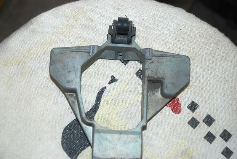
Ok, here is a yoke from a 89 and before, you can see that the clocking lugs are all the same size, as it does not matter in which direction the posts are clocked.
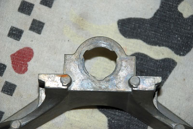
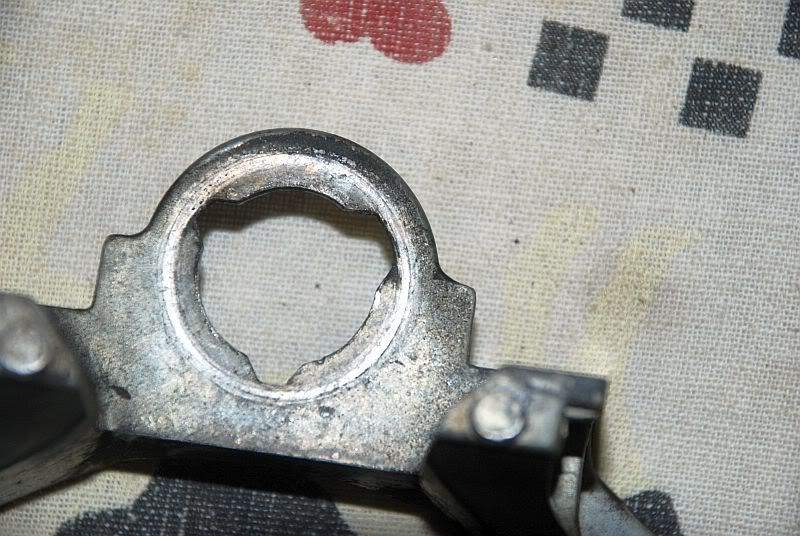
Here is the 90 and up yokes, they have a master lug (a bigger and wider lug at the 2 o'clock position) so the motor can only be clocked one way and have a slightly bigger hole.
The part numbers in PET are different for a 89 and a 90.
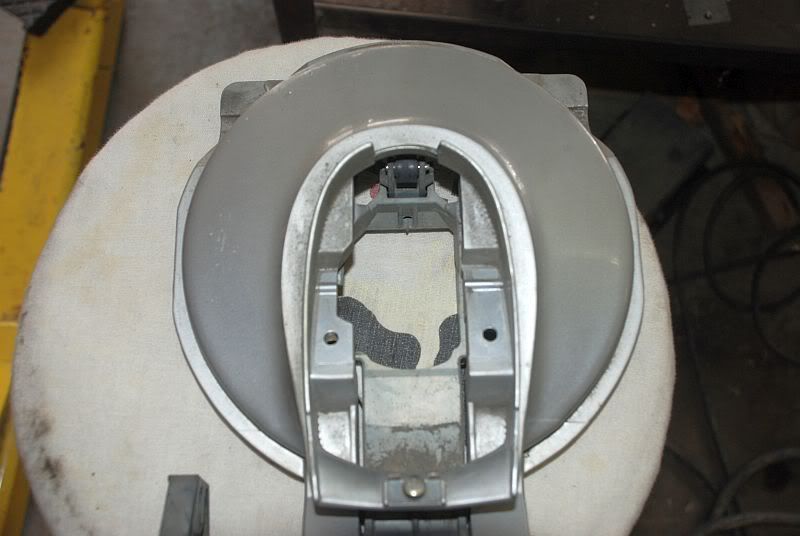
This is the part that I was not expecting, the part numbers in the PET I have show no difference in the 89 and 90 models, but the motors are s imply not going to fit in the swivel frames (that is the painted part) or the part below it that I can not seem to find the nomenclature on.
This one is from a 89, you can see that both parts have square sides.
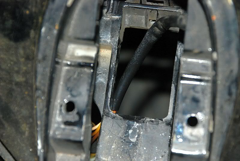
Here are the parts from a 90, very different from a 89.
So to do this on a 89 or older car you are going to need these six extra parts.
Here is the 90 and up yokes, they have a master lug (a bigger and wider lug at the 2 o'clock position) so the motor can only be clocked one way and have a slightly bigger hole.
The part numbers in PET are different for a 89 and a 90.
This is the part that I was not expecting, the part numbers in the PET I have show no difference in the 89 and 90 models, but the motors are s imply not going to fit in the swivel frames (that is the painted part) or the part below it that I can not seem to find the nomenclature on.
This one is from a 89, you can see that both parts have square sides.
Here are the parts from a 90, very different from a 89.
So to do this on a 89 or older car you are going to need these six extra parts.
02-03-2012, 04:28 PM
#101
Electron Wrangler
Lifetime Rennlist
Member
Lifetime Rennlist
Member
Thread Starter
Alan
02-03-2012, 10:25 PM
#102
Under the Lift
Lifetime Rennlist
Member
Lifetime Rennlist
Member
So, 90+ came with wiring for the pot, -89 did not. Greg's findings about the yokes make sense. I got H4's with yokes from an earlier car, so I'm in the same bind as Greg.
02-04-2012, 06:46 AM
#103
Pro
Join Date: Jan 2005
Location: Near London U.K.
Posts: 537
Likes: 0
Received 0 Likes
on
0 Posts
Could someone...(Alan) put up a wiring diagram for the control curcuit for an idiot, as i want to do this on my 84 so i can have HID. The mot over here has just changed to require levelling on hid lights
Thanks
Geoff
Thanks
Geoff
02-06-2012, 07:05 PM
#104
Electron Wrangler
Lifetime Rennlist
Member
Lifetime Rennlist
Member
Thread Starter
Geoff,
It actually rather simple - words will do I think:
Pins 1,2 & 3 get connected together on each motor and the Potentiometer unit - So all the pin 1s connect together, all the pin 2s connect together and all the pin 3s connect together. So you need a 3 wire connection from the potentiometer, through the firewall to the 1st motor and daily chain on to the second motor.
Pin 1 is the power feed - supply it from your marker lights (avail in the front fender area beneath the headlamp) - use a 1A fuse (or a 3A if its easier to find).
Pin 3 is ground - ground where the headlamps ground (run it seperately though) e.g. next to final stages at front.
Pin2 only connects between the motors and potentiometer
Alan
05-12-2012, 10:43 PM
#105
Rest in Peace
Rennlist Member
Rennlist Member
Join Date: May 2006
Location: Bird lover in Sharpsburg
Posts: 9,903
Likes: 0
Received 2 Likes
on
2 Posts
We got mine finished up Friday, Mike finished up the wiring for the adjustable part and this is a really neat addition in my book.
I still have to do the relays for the lights, but that will be simple enough.
I still have to do the relays for the lights, but that will be simple enough.