
View Poll Results: Interested?


Voters: 29. You may not vote on this poll
32V Cam Timing Tool & 16V/32V Conv 'Group Buy' #2
 02-09-2005, 07:27 PM
#61
Inventor
Rennlist Member
Rennlist Member
Thread Starter
In post #52, I was incorrect in saying that the GT cams measured (2) degrees advance. After adjusting and rechecking both cams with the dial indicator, the actual measurement is (1) degree advance for both sides.
I picked up the new batch today. I need to do some quality control checks and then they'll be ready to ship.
I have enough pictures for the manual, and I'm working on the copy.
I picked up the new batch today. I need to do some quality control checks and then they'll be ready to ship.
I have enough pictures for the manual, and I'm working on the copy.
 02-10-2005, 11:35 PM
#62
Inventor
Rennlist Member
Rennlist Member
Thread Starter
The pointers were bent incorrectly. Shop says they cannot guarantee bending to tolerance. (The first two were a fluke that they turned out right.)
Perhaps a two piece design could work, but I'm done.
Thanks for all your support, and suggestions.
Refunds going out tonight! (If you have been shipped a pointer, you must return it to me for refund.)
The 16V kits are fine, those will ship shortly.
Perhaps a two piece design could work, but I'm done.
Thanks for all your support, and suggestions.
Refunds going out tonight! (If you have been shipped a pointer, you must return it to me for refund.)
The 16V kits are fine, those will ship shortly.
02-10-2005, 11:44 PM
#63
Banned
Join Date: May 2001
Location: The Great Northwest
Posts: 12,264
Likes: 0
Received 3 Likes
on
3 Posts
Sorry to hear that Ken. You put a lot of time and effort into this, including many trips cross town during rush hour
I have no doubt your next project will turn out much different.
I have no doubt your next project will turn out much different.
Originally Posted by PorKen
The pointers were bent incorrectly. Shop says they cannot guarantee bending to tolerance. (The first two were a fluke that they turned out right.)
Perhaps a two piece design could work, but I'm done.
Thanks for all your support, and suggestions.
Refunds going out tonight! (If you have been shipped a pointer, you must return it to me for refund.)
The 16V kits are fine, those will ship shortly.
Perhaps a two piece design could work, but I'm done.
Thanks for all your support, and suggestions.
Refunds going out tonight! (If you have been shipped a pointer, you must return it to me for refund.)
The 16V kits are fine, those will ship shortly.
02-11-2005, 12:01 AM
#64
Addict
Rennlist Member
Rennlist Member
Ken,
Sorry about the production problems. It was a great idea, and you put a hell of a lot of time into it without even owning a 32v 928.
If you could be convinced to lend out the working set, let me know. I really don't want to pull my cam covers yet(powdercoating, then pull the intake again to PC match) to align the cams.
Hey, maybe you could try your hand at an x-pipe instead!
Jim R.
02-11-2005, 02:57 AM
#65
Inventor
Rennlist Member
Rennlist Member
Thread Starter
Thanks Jim(s),
I made the mistake of trying to design something that I do not have ready access to. With the 16V kit, I could easily stare, measure, stare, measure, and test on my own car.
The tight tolerances are also a problem for ready design of such a tool. I would not want to put something out there that gives inconsistent results.
I figure the working two cost about $600 each. I hope Jim_H will give me his back, so I can resell them both as 'limited editions'.
02-11-2005, 01:08 PM
#66
Rennlist Member
Ken, I ran this by my brother (http://www.prototype-design.com/) and he had the following to say... may/may not be of use to you, but what the hey:
Dave,
I can suggest Quality Metal Fabrication in Auburn, 530-887-7388.
I'm reasonably certain they can hold his tolerances, and quite certain that if they say they can, they can. If they don't think they can, they will say so.
I have little chance of being able to mill/drill that part in the flat and bending it up accurately enough for everything to line up and work. I'd have to machine separate parts and assemble.
Hmm, one suggestion you might pass along however, consider moving the timing index holes to the plate that bolts to the pulley and having a single point pointer at the timing mark. If the circular ring were larger in diameter, coming out near the pulley ID, should be able to keep holes far enough apart. I'd suggest opposing holes 180 degrees apart for each adjustment position. The adjustable indicator part would need a pair of press fit pins to match the holes in the circular plate.
A couple Pem studs coming up out of the circular plate and mating with adjustment slots would secure the indicating arm to the circular plate.
This would move the precision away from a bending operation.
Would be happy to try to communicate this idea a bit further with Ken.
Jon
His email address is on the page linked above. He's done quite a bit of very creative problem-solving; far more than he's had time to post on his site. might be worth shooting him a note or call.
02-11-2005, 01:26 PM
#67
Three Wheelin'
Join Date: Dec 2003
Location: Vancouver, Canada
Posts: 1,729
Likes: 0
Received 0 Likes
on
0 Posts
Ken,
Please don't give up on this project yet! Contact Dave A.'s brother as he suggests. I think this thing is too important. Step back and take a break if you must, but don't let it die.
Glenn

Please don't give up on this project yet! Contact Dave A.'s brother as he suggests. I think this thing is too important. Step back and take a break if you must, but don't let it die.
Glenn
02-11-2005, 02:56 PM
#68
928 Collector
Rennlist Member
Rennlist Member
Ken, how about simpler? We know the cam can move only so far between the slot ends on the 32V. Can we assume properly-adjusted cams and just mark the cam gear so that it actually reads how much advance/retard? I see no reason actually to go beyond that.
03-03-2005, 11:32 PM
#69
Inventor
Rennlist Member
Rennlist Member
Thread Starter
After some time away from this project, I came up with a simple fix. A laser width line, cut through 1/4 the width of the arm, forces a bend at the critical 90 degree section. (I also added a flat on the arm end for easier setup by the shop, and they spend more time on the setup.)
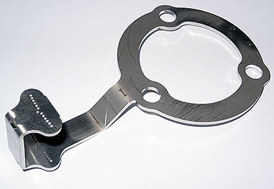
The cut does not affect the strength, it is still difficult to bend.
I'll post a new thread for this final version, once the manual is finished, as this thread is too long now.
The cut does not affect the strength, it is still difficult to bend.
I'll post a new thread for this final version, once the manual is finished, as this thread is too long now.
03-04-2005, 12:04 AM
#70
 Help me here Ken.
 I have the 16V ones with the white painted pointer thingy.
I have the 32V ones (I think) with the bends and little rippes at the outer edge and some nice stainless hardware.
I see a pic below that looks really cool - would these work for both cars (32V and 16V) or should I be sending one of my other sets back to you?
") I took my fenders off - great place for some fixed light brackets
I took my fenders off - great place for some fixed light brackets 

Originally Posted by PorKen
After some time away from this project, I came up with a simple fix. A laser width line, cut through 1/4 the width of the arm, forces a bend at the critical 90 degree section. (I also added a flat on the arm end for easier setup by the shop, and they spend more time on the setup.)
The cut does not affect the strength, it is still difficult to bend.
I'll post a new thread for this final version, once the manual is finished, as this thread is too long now.
The cut does not affect the strength, it is still difficult to bend.
I'll post a new thread for this final version, once the manual is finished, as this thread is too long now.
03-04-2005, 12:29 AM
#71
Inventor
Rennlist Member
Rennlist Member
Thread Starter
Originally Posted by BrendanC
1. I have the 16V ones with the white painted pointer thingy.
2. I have the 32V ones (I think) with the bends and little rippes at the outer edge and some nice stainless hardware.
3. I see a pic below that looks really cool - would these work for both cars (32V and 16V) or should I be sending one of my other sets back to you?
4. I took my fenders off - great place for some fixed light brackets
2. Those are the real 16V setup pointers. (see the pic in the beginning of this thread)
3. They only work with 32V engines. There are two separate kits, 16V conversions, and 32V cam timing tools.
4. I've got two projects in the works using my new sheet metal skilz. Fixed seat brackets (should lower seat by 3/4"), and fixed headlight brackets. The seat brackets, and the low beam bracket are done, I still have to design the high beam bracket (which replaces the US driving light), then send them all off to the laser/bending shop for another round of prototypes!
 04-18-2006, 10:10 PM
#73
Instructor

Join Date: May 2005
Posts: 203
Likes: 0
Received 0 Likes
on
0 Posts
Originally Posted by BrendanC
Help me here Ken. I have the 16V ones with the white painted pointer thingy.
I have the 32V ones (I think) with the bends and little rippes at the outer edge and some nice stainless hardware.
I see a pic below that looks really cool - would these work for both cars (32V and 16V) or should I be sending one of my other sets back to you?
I took my fenders off - great place for some fixed light brackets 