

Convert early fuse board to blade sockets
 12-12-2018, 04:19 AM
#61
Rennlist Member
Thread Starter
Update - 6+ years, zero issues almost - one fuse holder broke at a dry solder joint early into its life, replaced with a spare. 5 modified blade units in use.
jp 83 Euro S AT 57k
jp 83 Euro S AT 57k
 12-12-2018, 12:25 PM
#62
Rennlist Member
Why don't you email Roger?
Last edited by NewToPig; 12-12-2018 at 06:41 PM.
12-18-2018, 02:36 AM
#63
Rennlist Member
Thread Starter
Found a source of the 5/16 Female connector here sales=autoelectricalspares.co.uk@mail.ekm.net for reasonable price, including shipping. Some places in Oz want over $1 each for them. I plan to build a few units while I am not allowed to put any loads on right shoulder - rotator cuff repair. Will also look into making a bank of maybe 5 on a piece of circuit board to enhance the stability.
jp 83 Euro S AT 57k
jp 83 Euro S AT 57k
12-18-2018, 09:50 AM
#64
Rennlist Member
If these can get mass produced at a reasonable price, I will absolutely redo my entire fuse panel.
The stabilizer tabs are a great idea, and the plastic body should be color coded to the fuse.
You should find a manufacturer and do a Kickstarter for these.
The stabilizer tabs are a great idea, and the plastic body should be color coded to the fuse.
You should find a manufacturer and do a Kickstarter for these.
12-18-2018, 07:46 PM
#65
Rennlist Member
Thread Starter
Shawn,
I cant see anywhere enough demand to manufacture a specific solution to this issue, sadly. Unless maybe it could be used by millions of old VWs and other European cars of the period. I doubt these will have the same base connections, but you never know. Research into holders continues though.
jp 83 Euro S AT 57k
12-18-2018, 08:15 PM
#66
Pro

I'm pretty sure that my '81 Jetta would not have used these, as my memory seems to say it had permanently attached terminals.
(If it would have been an option, I would have jumped on one in an instant, back when I had the car. The stock GBC fuse design was a catastrophe, even with a 12 year old car...)
(If it would have been an option, I would have jumped on one in an instant, back when I had the car. The stock GBC fuse design was a catastrophe, even with a 12 year old car...)
12-20-2018, 02:00 AM
#67
Electron Wrangler
Lifetime Rennlist
Member
Lifetime Rennlist
Member
The other approach that I think Jake did - simply saw & power file the fuse-holder section off from your <'85 relay panel - then saw the relay portion off off an 85+ panel with ATC fuse holder section (may need to truncate for width) and then epoxy weld the 2 parts together - then wire directly to the late model fuse blocks. If you could find a broken 85+ panel (usually its the weaker relays and sockets sections that are broken) then it may not be too prohibitively expensive (? maybe).
It does provide a good starting point and all Porsche components - note that the circuit I/P side is now the top (not the bottom), some top connections are pre-wired to busses and some internal sockets are linked together INSIDE the fuse blocks (see my previous posts on this)
Still a viable alternative (but you need to adapt mounting to be a hybrid method). A huge amount of work to match up still (and some wires will need to be lengthened I'm sure)
Alan
12-21-2018, 10:51 AM
#70

Please do
12-21-2018, 01:29 PM
#71
Drifting
Another reason to do this. Tale recently posted to landsharkoz, but bears repeating.
A few years ago I replace the fuel pump relay. A few weeks ago, I went to start it, no dice. After a bit checking fuses, pulled the pump relay, put back in the original unit, fired right up. That replacement relay didnt last very long I thought. Went for a run, 40 mins out, died. Pump relay was hot to the touch. Bridged the relay, got home. mmmmmm. put in a generic 53 relay, pump started at turn on, I though OK, that will get me around until I can replace it. Went to start it today, brief catch, stopped. Bridged the pump relay , no pump....wriggled fuse 13 (listed by 928 specialist chart as pump), nothing. bridged releay again, and caught a spark out the corner of my eye, too far to the right to be 13....plugged the releay bridge in, wriggled fuses rightwards...fuse 22! Loose - no pressure on the ends, and the contact caps are not at all bright, or marked by contact. Put in one of my blade fuse holders, now have pump reliably. Went to start it, but could only get small catches, wouldnt take any throttle with the generic 53 relay. Put the OLD relay in, caught and ran fine right away. Looks like a 53 isnt a usable temporary fix, at least at a cold start, with CIS. Now I suspect that the relay failures have been caused by poor contact at the fuses causing an increase in current .....
About to send out some test fuse holders to a couple of users here, and a pair to Alan next week.
Looks like I have to use an earlier NY fuse chart, or at least the list in the Owner's Manual.
jp 83 Euro S AT 54k


 12-22-2019, 12:25 AM
#73
Rennlist Member
Thread Starter
Back to this a bit. Ducman82 - how did you arrange an equivalent of the multi fuse input bus as seen on early boards? eg, I have a board ending in -03 (dated 79), and fuses 14-23 all have one common power input in a large piece of bent steel, with only a couple of input leads. Dont see anything like that in your pics?
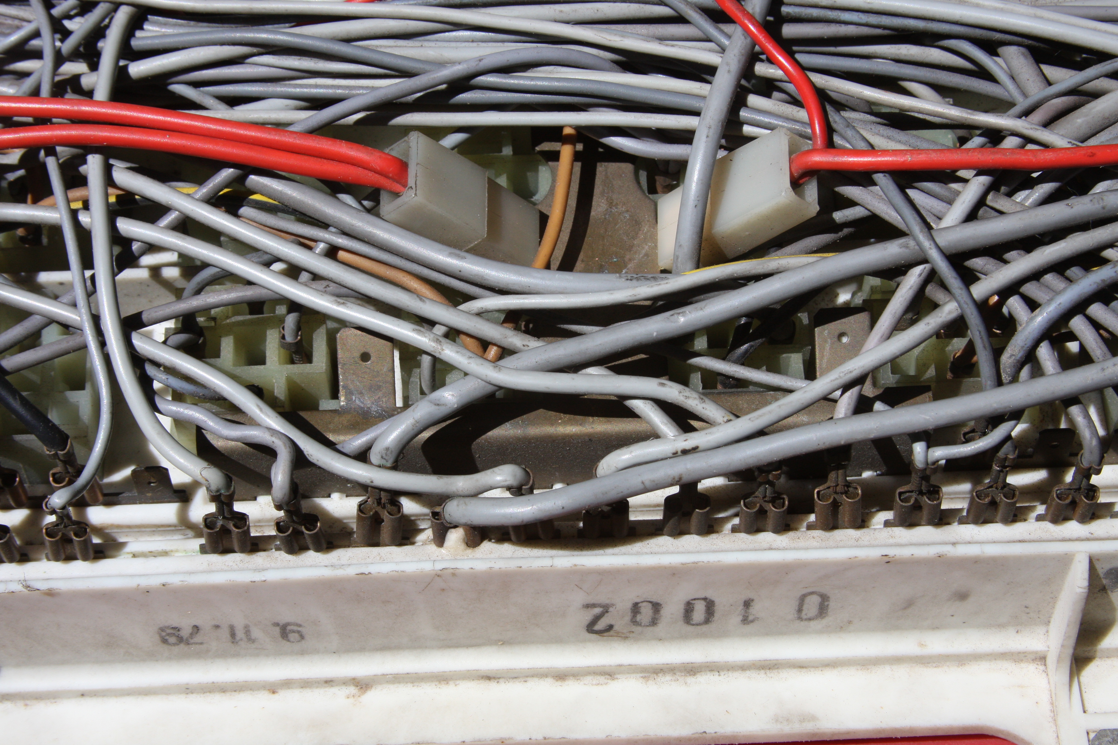
Centre - large plate, with supply from the red leads .
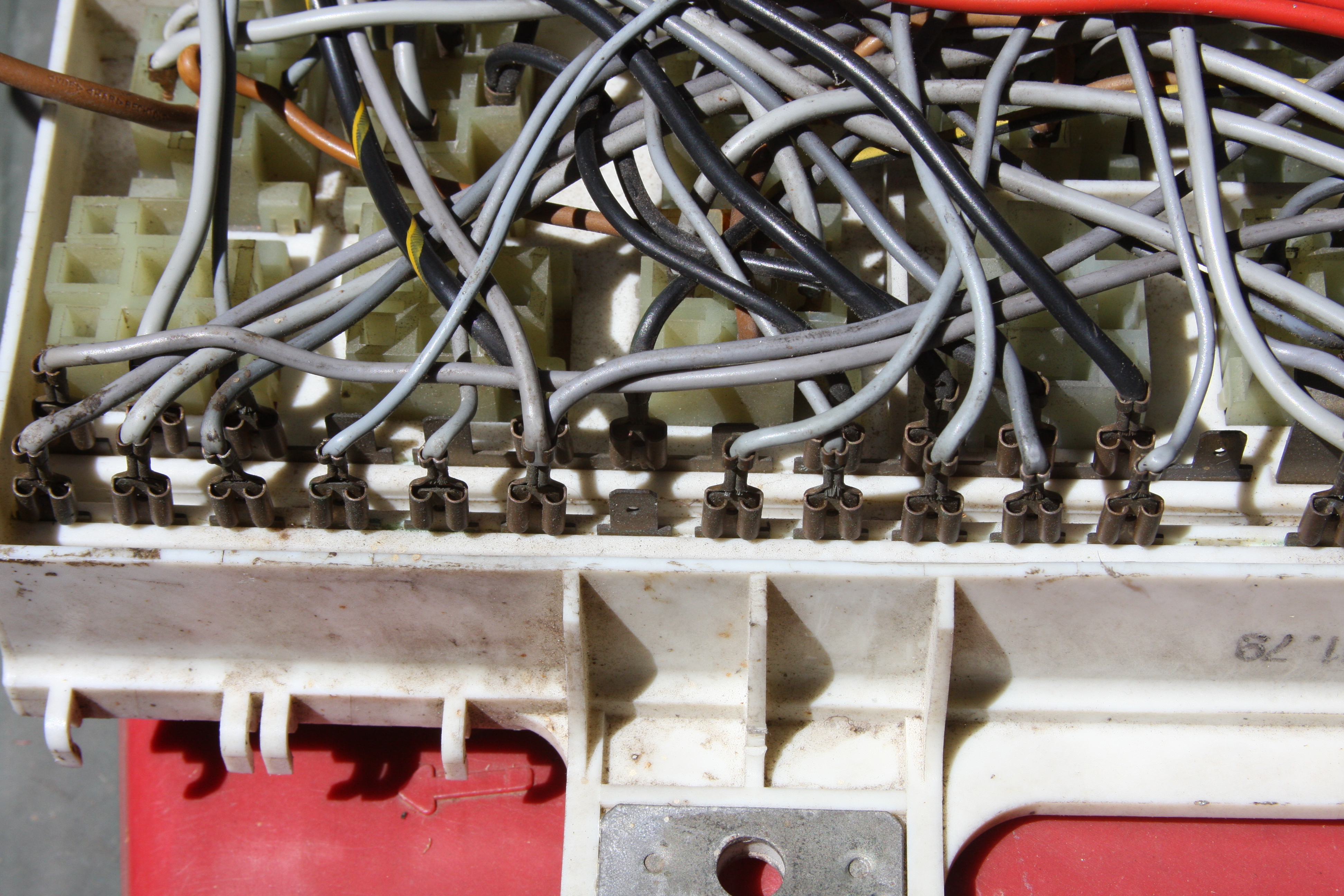
Left end - fuses 3-4 and 5-8 and 9-13 have common inputs.
thanks
jp 83 Euro S AT 57k
Centre - large plate, with supply from the red leads .
Left end - fuses 3-4 and 5-8 and 9-13 have common inputs.
thanks
jp 83 Euro S AT 57k
12-22-2019, 05:56 PM
#74
Electron Wrangler
Lifetime Rennlist
Member
Lifetime Rennlist
Member
You may need to reorganize the wiring. The fuse input on the <85 panels is the lower fuse connector and the output is the top. As you note there are some bus bars on the lower connectors - for (30) connections.
On the newer 85+ panels the fuse output is the bottom connector with fuse inputs at the top. Some of the top connectors are fed directly from the main bolt on battery (30) bus at the top via fold over metal tabs, Each 5 way modular fuse holder can also have internal bus bars shorting together from 0 to all 5 input connections. It is always best to check these electrically (and/or visual after opening the modular fuse blocks). On 85+ panels: (30) connections, (15) connections and (X) connections are all ganged in this way.
Alan
12-25-2019, 11:08 PM
#75
Rennlist Member
Thread Starter
Now plan to progress this a bit more. Two things have encouraged me - colour coded holders, and a (hopefully) more usable 5/16 female socket for the inputs (lower rail). Keystone now do the 3557 holders in Blue, Red and yellow, as well as the basic black - usually these colours correspond to 15A, 10A and 20A fuses. I plan to use the Reds 7.5A for our 8A fuses ( no Brown being available, using 10A if the 7.5s blow), Blue for 15A where our boards call for 16A, and the basic black for 25A fuses. Lately on repeating the search for 5/16 female sockets a local supply of straight entry pieces came up, so I hope these will be easier to solder to the holder pins.
Doing a bit more testing of installed holders I found that a little tightening of the curved parts of the female improved their grip on the board males enough to enable repeated fuse insertion and removal without loosening the holder, so they will be more stable.
As soon as I get some parts and test them I will report back with some pics. I looked at the idea of connecting holders together in groups, but felt that the increase if fitting and removing pressure would be detrimental, especially in view of the stability obtained with the tightened females.
jp 83 Euro S AT 57k