When you click on links to various merchants on this site and make a purchase, this can result in this site earning a commission. Affiliate programs and affiliations include, but are not limited to, the eBay Partner Network.
Calculated Coil Dwell Times (and measured inductance/resistance)
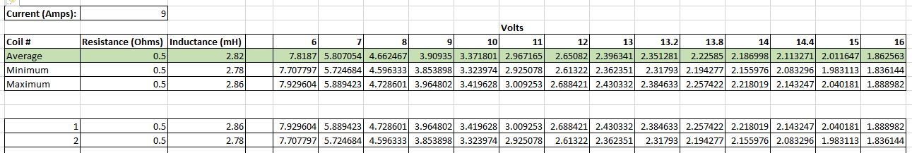
For those that may need the dwell times for the 1985+ 32v coils (Bosch 0221118322), below is a screenshot of an attached spreadsheet that calculates dwell times at various voltages. The two coils listed were extras on my spares shelf that I measured the inductance and resistance on. It's not a very big sample set, and you should always measure your own coils, but this should give you valid data points to start with. The spreadsheet is already configured for 20 samples, just fill in the extra lines. You can also change the voltage numbers to match whatever you need for your particular ECU's dwell table.
For those that may need the dwell times for the 1985+ 32v coils (Bosch 0221118322), below is a screenshot of an attached spreadsheet that calculates dwell times at various voltages. The two coils listed were extras on my spares shelf that I measured the inductance and resistance on. It's not a very big sample set, and you should always measure your own coils, but this should give you valid data points to start with. The spreadsheet is already configured for 20 samples, just fill in the extra lines. You can also change the voltage numbers to match whatever you need for your particular ECU's dwell table.
Using the following equations, one can determine the needed coil charge time for a minimum spark of 60 millijoules;
Coil Energy = 1/2 * L * I^2; L coil inductance, I coil current
Coil Voltage = L * I / T
For V (coil voltage) = 12 volts, L = 3 mHenries
Required I = 6.3 amps, Required coil charge time = 1.6 ms
__________________
Loren
Systems Consulting - Automotive Electronics
Specializing in Porsche cars http://www.systemsc.com/
How do you know that 60 mJ is the minimum needed? Do you have a source to validate that threshold?
Your equations are standard energy conversion formulas, but don't account for gap, temperatures, AFR, pressure increase in forced induction motors or even effects of compression ratio. All of which are factors in minimum spark energy. You're just working backward from an assumption that 60mJ is the minimum. If 60mJ is the minimum energy to ignite (aka MIE) a gasoline mixture (not accounting for loss in wires, plug material, etc) in all scenarios and conditions, there should be a reference to back that up, right?
And where did you come up with an inductance of 3mH? That's not what I measured on the coils. Do you have a spec sheet for the Bosch 055 or did you just round up from my measured values?
You also didn't account for primary circuit resistance, which is why your dwell time is inaccurate when targeting 6.3A at 12V.
I interpreted Loren's post to be: Using the following equations, one can determine the needed coil charge time for a minimum spark of 60 millijoules (as an example.)
I don't believe he was offering up an absolute required amount of energy, but simply an example, to show how to one might take your data a step further.
How do you know that 60 mJ is the minimum needed? Do you have a source to validate that threshold?
It's not an absolute value, just a basic value I've determined over the years. You have a better value?
You're aware that you have an implied coil energy too in your chart values, i.e. you have defined
coil inductance (2.8 mh) and coil current (9 amps), right? Why have you chosen 113 mjoules as the spark energy, 1/2 L X ( I^2)?
Originally Posted by Bulvot
Your equations are standard energy conversion formulas, but don't account for gap, temperatures, AFR, pressure increase in forced induction motors or even effects of compression ratio. All of which are factors in minimum spark energy. You're just working backward from an assumption that 60mJ is the minimum. If 60mJ is the minimum energy to ignite (aka MIE) a gasoline mixture (not accounting for loss in wires, plug material, etc) in all scenarios and conditions, there should be a reference to back that up, right?
So, what have you determined for minimum spark energy, besides your challenges?
Originally Posted by Bulvot
And where did you come up with an inductance of 3mH? That's not what I measured on the coils. Do you have a spec sheet for the Bosch 055 or did you just round up from my measured values?
Yes, I just rounded your values.
Originally Posted by Bulvot
You also didn't account for primary circuit resistance, which is why your dwell time is inaccurate when targeting 6.3A at 12V.
What was presented was not implied as part of a major research paper! A least some Rennlist members will have a basic understanding of an inductive discharge ignition
(IDI) system calculations as used on the 928 and not a CDI (capacitive discharge ignition) as used on the early Porsche 911s.
Those were honest questions. Not challenges. If you have the answers, especially the datasheet for the Bosch 055, that would be great.
I did not calculate maximum amps by working backward from an energy target. My understanding is that the 928 stock ignition modules are clamped at 9 amps. Any dwell time longer than it takes to get to 9 amps is wasted and heats up the coils with no benefit. That method is pretty standard practice with aftermarket ECU's. You figure out where either the control module clamps the amps, or where the coil charge ramp has a significant rate change. Then, you use that current to calculate your dwell time. I'm not making this stuff up, it's SOP.
If you have datasheets to share, I would love to see them. Bosch doesn't make it easy to get them on these coils and modules. But, I've found posts with oscilloscope measurements of the modules. Taking those results and L/R measurements of the coils provides the data to calculate the maximum dwell time.
I didn't spend a ton of time looking for MIE data, but I did find some research papers that measured MIE for gasoline motors. They cost money, though, and it just wasn't worth it to me to pay for those papers. Which is why I asked where your 60mJ number came from and if it accounted for worst case scenarios. I know that the stock coils and ignition modules work on my 11.6psi boosted motor, with stock spark gap, so blow out isn't an issue for me with whatever the stock ECU does (I assume 150 degrees dwell, 30 degrees spark duration at higher RPM's). What is important, though, is dwell time. Without having the factory ECU's dwell table to be sure of what they do and when, I have to work at it from the other direction. Which is what my spreadsheet does. Even if I had the factory dwell table, I would still want to confirm that it makes sense by calculating dwell time.
And if you're going to provide dwell times for coils to reach a particular current, you must also factor in the primary circuit resistance. It makes a big difference when you're using the result of that calculation in an ECU. If you make it too big, you could burn out the coil and/or ignition module. If you make it too small, you could have misfires or spark blow out. And you also have to factor in spark duration to consider maximum total dwell/spark duration available for each cylinder for any given RPM. It's important stuff. Just like knowing that the majority of the energy is expended in the first 25% or less of the spark duration. And that less than 20% of the calculated energy actually transfer to the fuel/air mixture.
I'm not an expert on this stuff, but I know enough to know that you can't simplify it and expect good results.
What is it you're trying to do?
1. Push the 928 Bosch ignition beyond its present design limits? If so, I doubt you'll gain much without a change in the ignition module or the coil,
and possibly reduce the system reliability. You'll need to fully evaluate your present Bosch coil and determine what dwell time causes it to saturate.
From that, you'll be able to determine the coil's maximum energy development.
2. Or if you plan on re-designing the ignition system then;
a. You'll need to use IGBT coil driver and avoid secondary breakdown.
b. You'll need to avoid saturating the ignition coil, as the coil driver current will only be limited by the coil's series resistance,
e.g. .20 ohms and at 12V is 60 amps driver current.
c. Ideally you'll need to begin the coil dwell time just before spark is required which varies based on RPM and the advance curve.
The bottom line for all the effort is determined by the dyno results!
I am calculating dwell time based on actual measurements of the coils. And I shared my measurements and spreadsheet for others who have the same need but lack the knowledge or tools to do the same. Dwell time must be adjusted for system voltage, which all ECU's do (including the EZK), so you need a range of dwell times. Or at least a specific nominal voltage dwell time. My spreadsheet provides a reasonable starting point for anyone using the stock coils and ignition modules with an aftermarket ECU.
You, or anyone, can plug in whatever amp target and R/L values you want. Feel free to do so if you have a need to calculate dwell time.
That's it. You threw out some generic formulas and stated a minimum energy requirement as though it were fact, so I asked for clarification and references.
If you have datasheets for the stock components, or actual test values, please share them.
I found some more information to make things easier for others in the future.
The Bosch 0.227.100.124 is often referred to as a "Bosch 124", but it's actually called a "BIM 027" internally by Bosch. When you search for "BIM 027", you'll start finding a lot more information.
Attached is the Bosch 124 specification sheet. It's not super detailed, but it does give it's maximum primary current. And, it confirms that it shares current specifications with several other ignition modules.
So, I've also attached the more detailed specification sheet for Bosch 203 (BIM 203), which has the same physical dimensions and current limits. The sheet doesn't state it, but all reports from other users of this line of modules is that the module will shutdown if it overheats (due to too much current being pulled due to too long of a dwell). It does list the maximum current as 10A at 120 Celsius, which is the reported thermal cut off point.
I've also attached a wiring diagram for the Bosch 124 (BIM 027).
With the attached information, and taking actual inductance and resistance measurements of the coils installed on the car, you can calculate maximum dwell time at any voltage. And then adjust that for your particular needs.
I am calculating dwell time based on actual measurements of the coils. And I shared my measurements and spreadsheet for others who have the same need but lack the knowledge or tools to do the same. Dwell time must be adjusted for system voltage, which all ECU's do (including the EZK), so you need a range of dwell times.
Yes, most know that!
Originally Posted by Bulvot
Or at least a specific nominal voltage dwell time. My spreadsheet provides a reasonable starting point for anyone using the stock coils and ignition modules with an aftermarket ECU.
You, or anyone, can plug in whatever amp target and R/L values you want. Feel free to do so if you have a need to calculate dwell time.
That's it. You threw out some generic formulas and stated a minimum energy requirement as though it were fact, so I asked for clarification and references.
If you have datasheets for the stock components, or actual test values, please share them.
Anyone that can solve basic algebraic equations, using the equations in post 44, can solve for what's needed in an ignition system design.
You're compilcating/confusing a simple issue!
You're right, your algebraic equation is very simple. Unfortunately, also inaccurate. It does not account for resistance and is working backward from an assumption about required energy. It's not an empirical assumption based on documented observations of a broad sample base, or based on math. It's an assumption.
I definitely would not want to use your equation as a basis for my new ECU. Why be inaccurate and base it on unsubstantiated assumptions when it takes the same level of effort to be accurate?
Being accurate is not complicating something, it's being accurate. Your inaccurate formula might produce a value that works. But it depends on many other unaccounted for factors. When tuning, you ultimately do what works, based on performance measurements. So, it's always better to start with as accurate of a configuration as possible, before beginning the evidence based tuning. Otherwise, you end up chasing your tail trying to figure out why something is performing unexpectedly, only to discover it's because your original assumptions and math were incorrect.
The correct formula for determining maximum dwell time (the time it takes for a coil to charge up to the desired amps) is: T = (-L/R) * ln( 1 - (R * I/E))
Which is easy to plug values into and arrive at an accurate answer. Or, use the spreadsheet and let it do everything for you.
Otherwise, you might as well just start at a random dwell number, decrease it by 0.1 second increments at idle until you get a miss, then increase it a little and call it good. Or, you could increase dwell until the ignition module and/or coil starts to get hot, and then decrease it a little. Those are the popular methods for determining dwell without using math.
Why are you getting so defensive and argumentative over a well known and documented scientific analysis of how inductive coils work? This isn't some napkin math that I dreamed up. This is a very standard and well known equation.
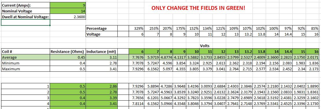
I got a couple of more values from Bosch coils. The resistances and inductances for each pair have been close to each other. Maybe related to the manufacturing lots, or maybe not.
Updated spreadsheet attached. I've been using 2.5ms dwell at 14v, with the voltage correction curve calculated by the spreadsheet, and it's been working really well with zero issues.


 07-21-2022, 12:07 PM