When you click on links to various merchants on this site and make a purchase, this can result in this site earning a commission. Affiliate programs and affiliations include, but are not limited to, the eBay Partner Network.
Well I have Rich sending a me a LH unit (I was calling it a ECU) to test, I will double test every connection I can. Also got four new relays coming that have a indicator light that shows they are on, will use them to see that the four primary relays are on when cranking. Also will put on the heavy duty alternator wire I just got from Greg and the ground strap (but mine looks good).
Dan Serrato
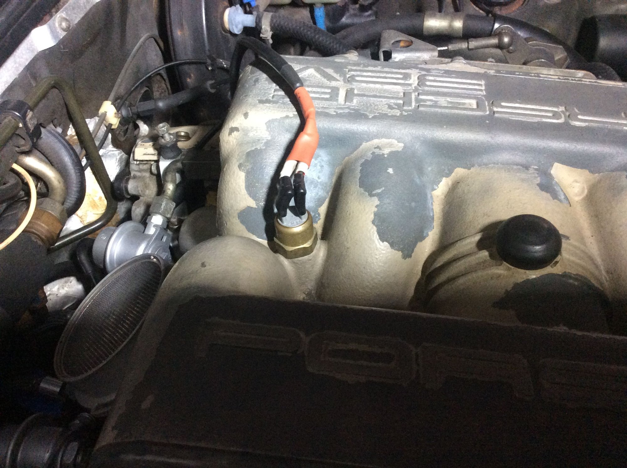
The sender I was laying on, it has a bent connector, can it keep the car from running?
If you have completed the tests suggested and got positive results then the LH is the last man standing as it were - best wishes for a conclusive test when the unit arrives.
One of the common things, which occurs in these cars, is for the injector wires to loose their insulation under the rubber boots (if the boots are still intact). Any accidental movement can cause the two wires on any injector (positive and negative) to touch each other.
The result is a short circuit which does not allow any injector signals to reach any injector.
Sometimes, just going around and straightening the wires out, right at the injector, will solve the problem.
Sometimes, more work is required....
If you disconnect all 8 injectors, the continuity through the coils in the injectors are eliminated.
At that point, with the key on, you should have 12 volts on one side of each injector connector, but no voltage on the other side. If you have voltage on both sides, you have a crossed wire at one of the injectors.
I keep injector connectors, the proper electical connects, and boots in inventory if you need to do loom repair. I have these pieces for all of the AMP ends (2, 3, and 6 pin connectors)
If the loom is beyond repair, I'm now making complete new looms (by special order only...no inventory, at this point) from very high grade TXL wire and aerospace shielded wiring.
Greg,
I have a 94 XJS V-12 and we have the same problems with wiring, the plastic is so brittle if you move a wire it just flakes off! I do not have 12volts at the front right but I do get power at the left front injector plug. I felt some cracking when I removed the right front to test it with a noid light and test the fuel pressure.
Rich said my LH box was good the first time I sent it, and he put in the new compaciters, it also tested good this time. I should get his loaner this week to test in the car, so will answer the question about my LH box.
I would like to replace the engine harness if Porsche used the same crappy wires that Jaguar used. How hard is it to change out the injector harness, does it go all the way to the computers in the pax footwell?
Will be putting the alternator on today, will not be able to test it until the car runs!
I just revamped my harness earlier this year. Started as an exercise to revamp the MAF connector and the injector pigtails with new connectors. Generally the cable problems are found between where the cables leave the loom and enter the connectors. The heat shrink will be like bakellite but that can be cut back. I then found the Hall sensor connector in pieces but without my knowledge it had been that way for at least 16 years even though i knew it was working correctly through my ST2 interface.
I used new junior powertimer connectors with the easy release integral clip but on the MAF connector the size of the thing complicated matters and I had to re-route the cabling some. I ultimately ended up revamping the entire harness from just behind cylinder No4 where the harness bifurcates. With hindsight it would probably have been easier to simply remove the harness in totality and work on it on the bench but there we are. For the MAF you need a 6 pin connector, for the Hall sensor, the CPS and the idle switch connector you need 3 x 3 pin connectors. The rest are two pin connectors and you will need something like 12 of these if my memory serves me correctly [easy to add them up]. I also segregated the fuel injector leads from the other leads to help with layout.
I was surprsied at how crude the injector wiring was- it simply started as a single wire and progressively bifurcated until there were 8 wires. Mine had no continuity problems- the wires tested for continuity from LH plug pin 18 through to the injector and there was no cross connection between the feed and earth cabling. Hopefuly you tested these correctly.
So pulled the LH plug from unit, #18 pin in the plug with a male pin, and checking the first right front injector plug shows zero resistance on both sides! Now one should show no continuity? The red/yellow wire with the LH plug hooked up shows 12 volts but also the brown/red has 12 also! This same both banks first injector plugs!
Can someone explained that?
Now my helper, ask should all eight injector plugs be pulled to test the #18 pin? That having tested just the two front ones the other six being connected gave us these results.
There is nothing complicated going on here. 12 volts is supplied from the LH relay contact 87 when the ignition is switched on and this splits to feed all 8 injectors [the "red" cores]. If just one injector plug is connected to an injector there will be continuity across the injector and thus through to all plug earth side connections [brown cores]. There must be no continuity to earth - the LH unit internal switching grounds the earth connections to fire the injectors.
You should only find 12 volts in the circuit when the ignition is switched on and the LH relay is thus energised. Thus disconnect all the injector plugs and test the earth side for continuity to the LH plug terminal 18.
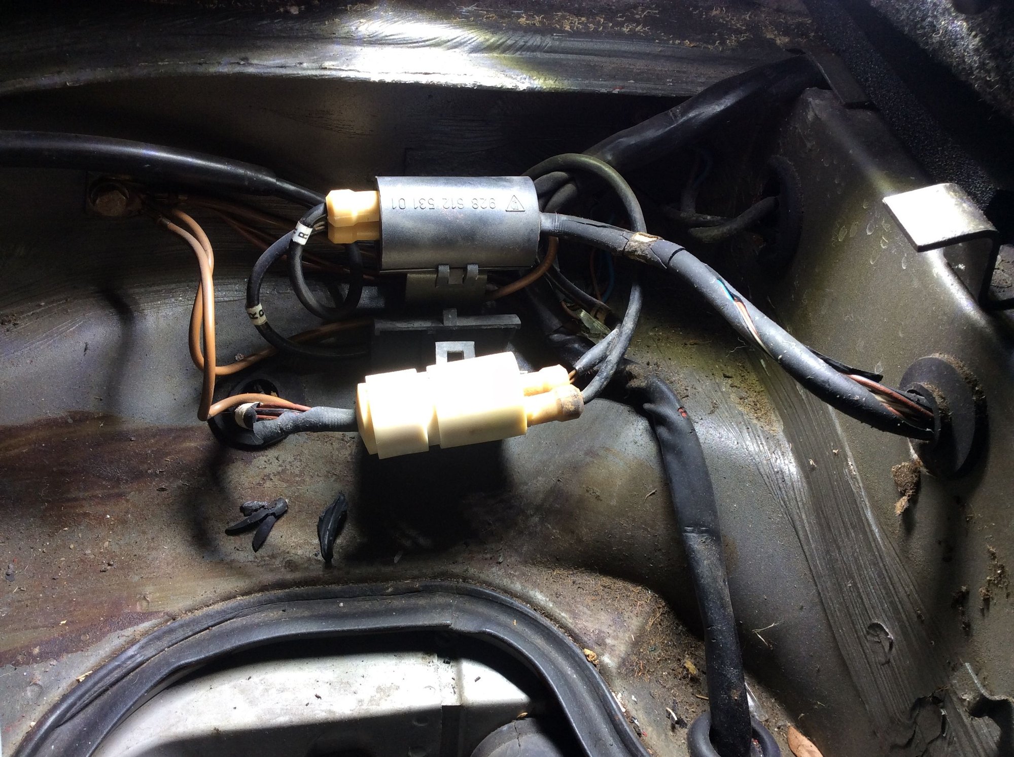
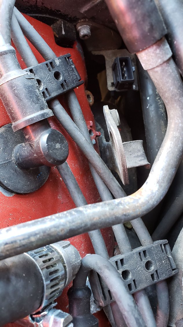
These are left and right ABS sensor and brake pad wear sensor barrel connections.
NOTE the pad and ABS wires have different shaped connectors and will only fit into one hole ,
make sure to mark the connectors and bodies prior to taking them apart.
Check/clean the ground wire bundle next to the anchor plate for the connectors
Update, still was working the starting issue, but had ordered a Temp II sensor, it came today, put it in and the car started! So I guess it needs to be working to start a cold engine! Will update my other post.
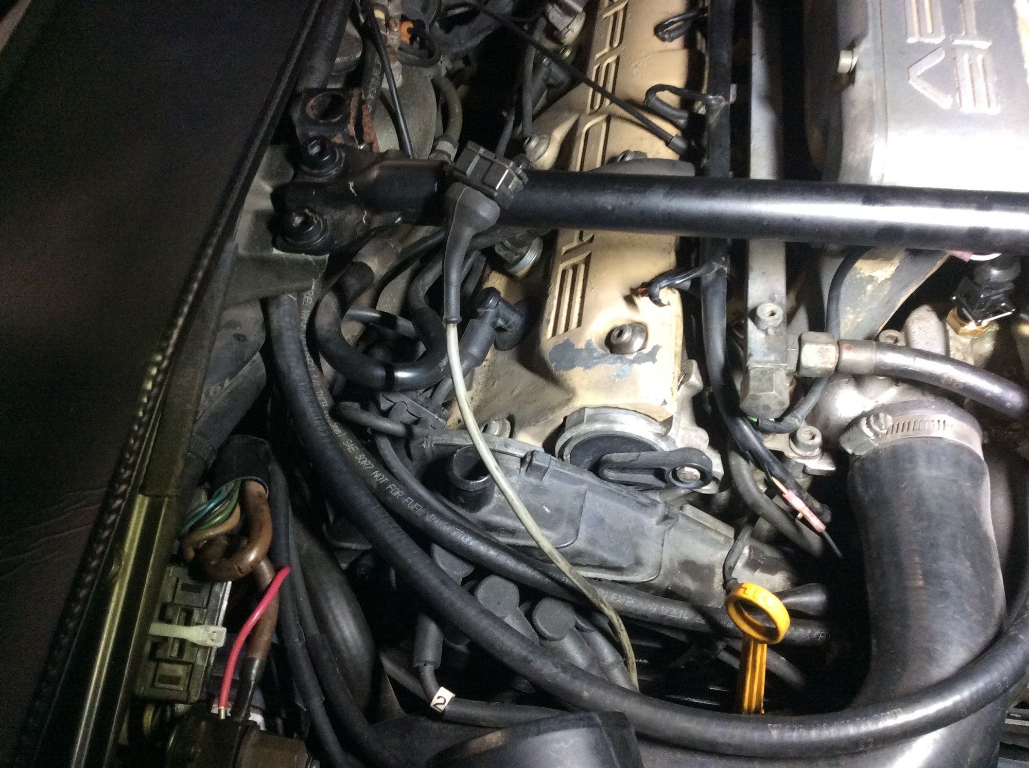
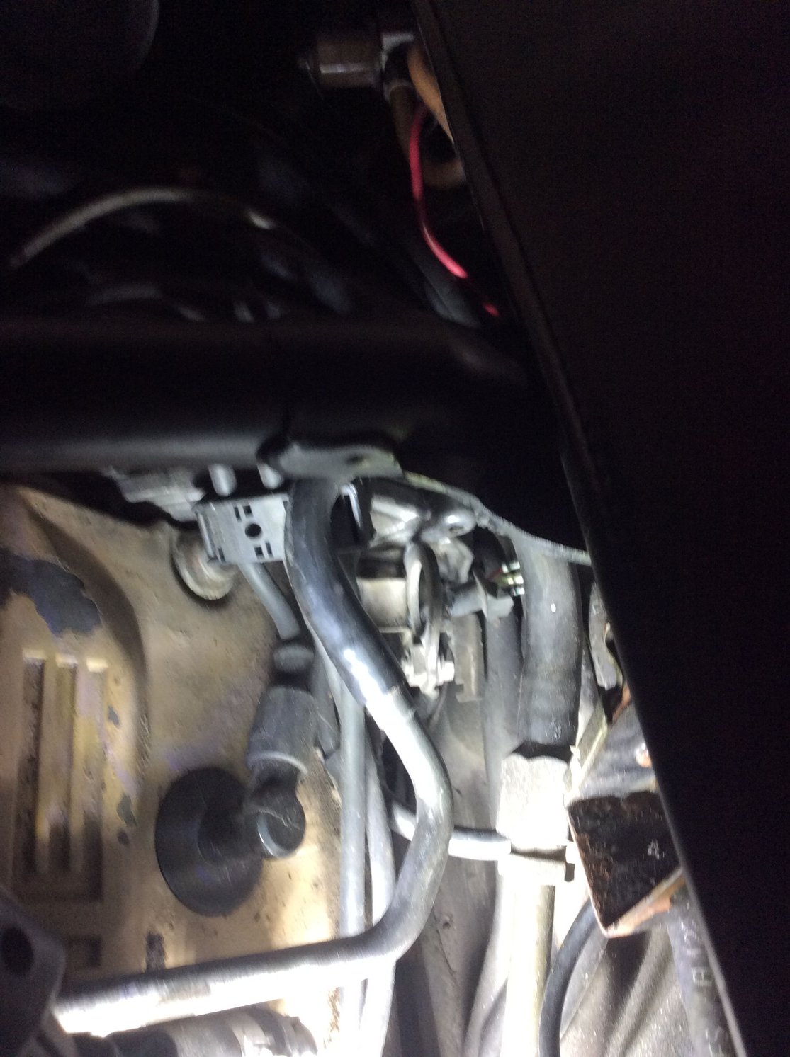
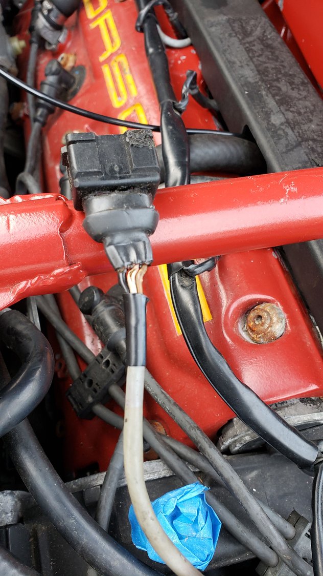
OK, the engine ran after the new Temp II sensor was put in, then it stoped again, so I think moving my right front FI cable is where the problem is. Got 12 volts to all injectors, and moving the harness in that area seems to affect the cranking. The right rail cable goes down and under the right coolant hose and the heavy gray cable runs under and behind the jump post to a three pin plug that fell apart when I moved it. Here is the cable and a photo of where the broken three pin plug is. This is the cable I pulled it up to show. Whet does it do? The broken plug is down in there, where the gray cable goes.
I too am curious about this gray cable as I am also replacing mine. I discovered mine had wires that were coming apart during the refresh of my intake manifold. I have the 3 pin female cable and Temp II sensor on order from Roger as we speak. I have attached the link for the cable if you want. Female: https://928srus.com/products/3waybos...pr_seq=uniform
The last two posts show the Hall sensor [male] connector. The cable is shielded hence three cores, one being the screen. for reasons I do not understand the male connectors appear to be very vulnerable to crumbling. It happens on the knocks sensors, the CPS and the Hall sensor- they literally fall apart leaving the three male connector spades exposed even though they may still be engaged and even working [in some cases].
if the Hall signal fails the EZK unit will retard the ignition by 6 degrees and that is a considerable penalty power wise but the motor should still run. This happened on my LH/EZK harness earlier this year. Unofrtunately I did have a spare male connector to hand so I used the terminals and in effect spliced an extension onto the Hall sensor to give me some cable to play around with routing wise. Fortunately I have Sharktuner ST2 and this tells me that I have viable contact for the Hall sensor [or not] as the case may be.

 11-06-2021, 10:27 AM