When you click on links to various merchants on this site and make a purchase, this can result in this site earning a commission. Affiliate programs and affiliations include, but are not limited to, the eBay Partner Network.
Today I began dismantling my spare set of heads for assessment as to what was required to put them into service.
BOTHER!!!!!!!
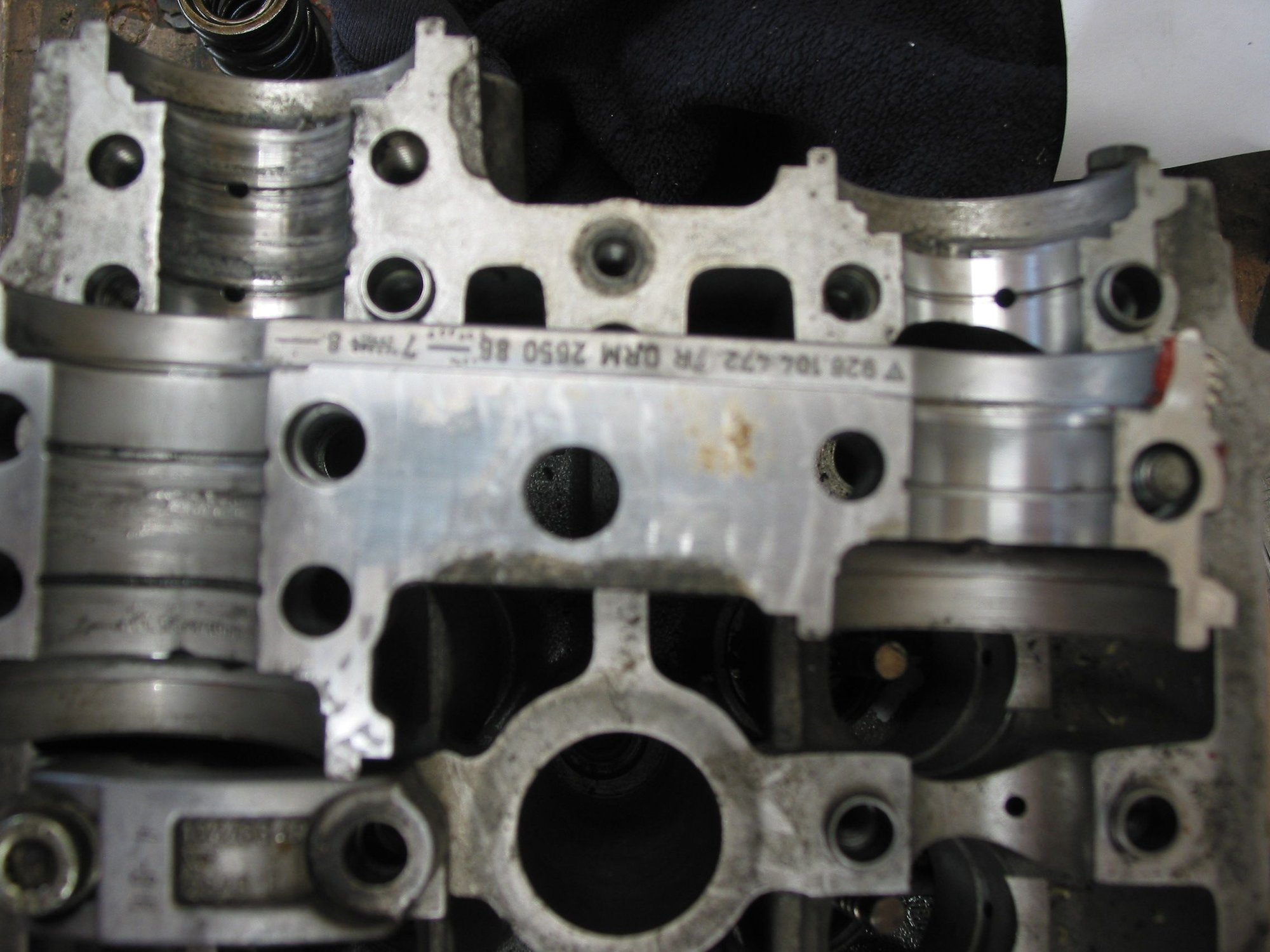
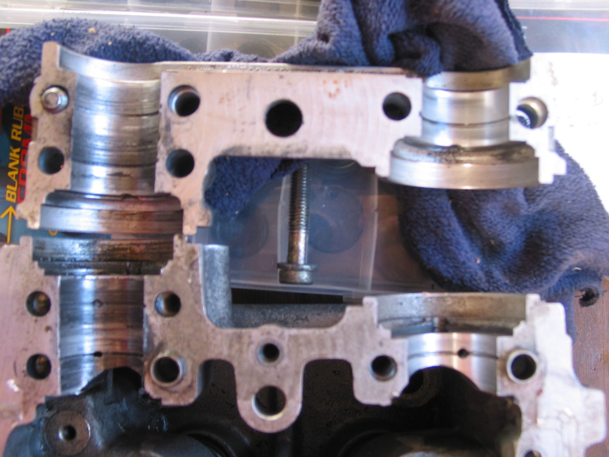
Both heads have damaged cam journals where the cam snouts protrude through and are driven by the cambelt.
One of the heads doesn't have a matching numbers cap for this area either.
Might come down to which is easier to get repaired - the head surface corrosion (particularly where it goes under the fire ring) or the camshaft journals.
GREG - I could really use that list of tips / tricks for repairing these heads......please.......
As an aside, does anyone have a new intake and exhaust valve they can measure the stem diameter (to 0.001mm) for me please. The factory specs seem to be 6.97mm for intake and 6.94mm for exhaust and I am getting numbers within 0.01mm of this. Just wanting to know if new is +/- 0.005mm or less so I can assess if new valves needed.
Both sets of head have lots of valve guide slop (no need to measure to know it's out of (even porsche) spec, so new guides are in the future, whichever set of heads I use. Not surprising as this seems to be a known wear point. Can anyone advise if it is best to go with OE , OEM or aftermarket on these?
Today I began dismantling my spare set of heads for assessment as to what was required to put them into service.
BOTHER!!!!!!!
Both heads have damaged cam journals where the cam snouts protrude through and are driven by the cambelt.
One of the heads doesn't have a matching numbers cap for this area either.
Might come down to which is easier to get repaired - the head surface corrosion (particularly where it goes under the fire ring) or the camshaft journals.
GREG - I could really use that list of tips / tricks for repairing these heads......please.......
As an aside, does anyone have a new intake and exhaust valve they can measure the stem diameter (to 0.001mm) for me please. The factory specs seem to be 6.97mm for intake and 6.94mm for exhaust and I am getting numbers within 0.01mm of this. Just wanting to know if new is +/- 0.005mm or less so I can assess if new valves needed.
Both sets of head have lots of valve guide slop (no need to measure to know it's out of (even porsche) spec, so new guides are in the future, whichever set of heads I use. Not surprising as this seems to be a known wear point. Can anyone advise if it is best to go with OE , OEM or aftermarket on these?
Cheers,
Myles
Don't forget that the heads are interchangeable from side to side, in an '87 to '95 928.
If the cam journal damage is limited to just those two front journals (along with the mismatched cam cap), you could switch the heads around, so that those damaged journals are at the rear....where they do absolutely nothing.(And where any cam cap would work.)
You are looking more for "taper" in the valves....where there is differential wear in different places on the stems.
Not to mention that it takes one hell of a accurate digital micrometer to measure .005mm. The temperature of the room will throw off a measurement more than that...
And don't forget, you've got two head sets of valves to pick from.
Factory valve guides come oversize....and each guide needs to be machined and fitted to each hole.
Almost no one will want to do this...nor have the tooling/experience to machine 32 valve guides concentric and to the exact size required.
Try "PEP" for valve guides.
If the guides get removed correctly (cored 90% of the way (from the valve seat direction) and then pushed out using the remaining "step" on the "seal" end, the holes will almost always take a true "standard" guide. PEP offers guides in oversize dimensions, also. Some of the "aftermarket parts idiots" sell guides in .001" oversize and just tell people to use these. Avoid that scenario.
If an idiot just hammers out the guides without coring them...all bets are off and divine intervention will be needed.
Either way, each guide hole will need to be cleaned, measured, and each guide will need to be measured, in order to get the proper fit.
After installation, the guides will need to be either reamed or honed to size. There are pros and cons about reaming versus honing. If the machinist has a "Hunger Valve Guide Reamer" in almost new condition, that is my preferred method.
If not, very accurate honing is possible, if the machine shop has high quality equipment.
Jay Leno, on his YouTube channel often mention using a waterless coolant to avoid rust issues on his cars. Any thoughts on this for a 928?
Horrible product for driven cars, for a lot of reasons.
Heavier (makes the WP and belt work harder)
Its never where you need it, so always carry 4 gallons with you because...
...you cant mix it with anything.
It's painting over solvable problems.
Sit a car to never drive it, sure, good product...I guess.
Don't forget that the heads are interchangeable from side to side, in an '87 to '95 928.
If the cam journal damage is limited to just those two front journals (along with the mismatched cam cap), you could switch the heads around, so that those damaged journals are at the rear....where they do absolutely nothing.(And where any cam cap would work.)
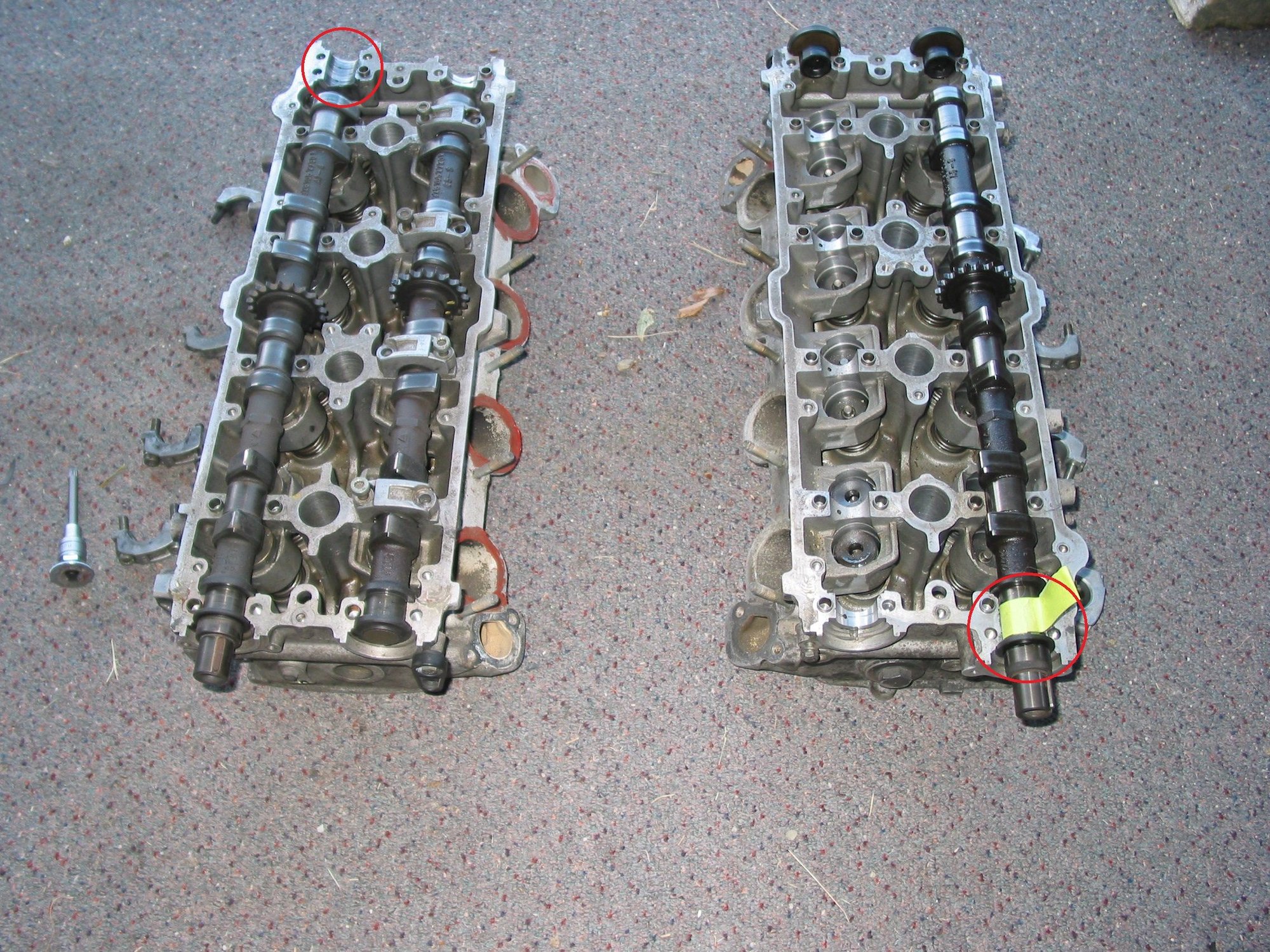
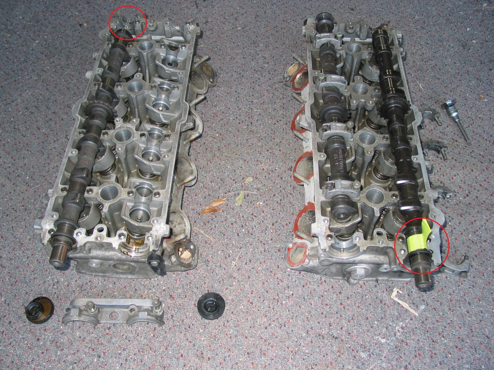
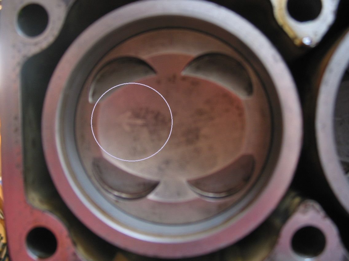
Greg, I respect your input very much but I cannot see how that will actually work. I still end up with a damaged journal being used. See photos below taken from different ends - red circles are damaged areas. Switching the heads around still means one damaged journal being used.
Originally Posted by GregBBRD
You are looking more for "taper" in the valves....where there is differential wear in different places on the stems.
Not to mention that it takes one hell of a accurate digital micrometer to measure .005mm. The temperature of the room will throw off a measurement more than that...
And don't forget, you've got two head sets of valves to pick from.
Thanks Greg. Valves to date (small sample) are measuring even with no taper (within accuracy of measurement). Using normal precautions - everything to same temperature (differential coeficients of expansion of valve vs micrometer vs calibration block should have a very small effect for a 7mm measurement), micrometer calibrated at '0'mm and immediately checked using standard at '25'mm and then back to '0'mm, micrometer in stand, gloves used to minimise heat transfer from hands to valve when measuring. Getting very consistent, repeatable results +/- 0.001mm across digital and mechanical micrometers.
Originally Posted by GregBBRD
Factory valve guides come oversize....and each guide needs to be machined and fitted to each hole.
Almost no one will want to do this...nor have the tooling/experience to machine 32 valve guides concentric and to the exact size required.
Try "PEP" for valve guides.
If the guides get removed correctly (cored 90% of the way (from the valve seat direction) and then pushed out using the remaining "step" on the "seal" end, the holes will almost always take a true "standard" guide. PEP offers guides in oversize dimensions, also. Some of the "aftermarket parts idiots" sell guides in .001" oversize and just tell people to use these. Avoid that scenario.
Greg, do you supply "PEP" valve guides?
Originally Posted by GregBBRD
If an idiot just hammers out the guides without coring them...all bets are off and divine intervention will be needed.
Either way, each guide hole will need to be cleaned, measured, and each guide will need to be measured, in order to get the proper fit.
After installation, the guides will need to be either reamed or honed to size. There are pros and cons about reaming versus honing. If the machinist has a "Hunger Valve Guide Reamer" in almost new condition, that is my preferred method.
If not, very accurate honing is possible, if the machine shop has high quality equipment.
Thanks Greg. Rather not have to invoke divine intervention so this is a very handy tip.
Greg, I respect your input very much but I cannot see how that will actually work. I still end up with a damaged journal being used. See photos below taken from different ends - red circles are damaged areas. Switching the heads around still means one damaged journal being used.
Not sure how the PO accomplished that....had to be the same mistake on 2 different engine assembly attempts, right?
Regardless. Stick the head with the mismatched cap, so that cap is at rear. Have your machinist see if he can cut the cap on the other head and align bore the two front journals. Common stuff to do, if the damage isn't crazy.
Thanks Greg. Valves to date (small sample) are measuring even with no taper (within accuracy of measurement). Using normal precautions - everything to same temperature (differential coeficients of expansion of valve vs micrometer vs calibration block should have a very small effect for a 7mm measurement), micrometer calibrated at '0'mm and immediately checked using standard at '25'mm and then back to '0'mm, micrometer in stand, gloves used to minimise heat transfer from hands to valve when measuring. Getting very consistent, repeatable results +/- 0.001mm across digital and mechanical micrometers.
Your methods put me to shame! Good job!
A sure fire way to get a base measurement on a valve is to measure the stem just below the keepers, where the valve stem never touches anything.
.001mm is non consequential, regardless.
Greg, do you supply "PEP" valve guides?
Can do.
Thanks Greg. Rather not have to invoke divine intervention so this is a very handy tip.
Cheers,
Myles
Notes in your text, cleverly not distinguishable. Not sure how to change text color on my phone....and not anxious to learn, at midnight.
Thanks Greg.
A cunning strategy to force me to read all your responses in context ?
One option I have though of is to use the better of my original heads (no incursion under the fire ring) with one of the spare heads orientated such that the damaged journal is not in use.
Ultimately looks like it will come down to comfort level with whomever I can get to do the work and relative costs for each type of repair.
Both sets of head have lots of valve guide slop (no need to measure to know it's out of (even porsche) spec, so new guides are in the future, whichever set of heads I use. Not surprising as this seems to be a known wear point. Can anyone advise if it is best to go with OE , OEM or aftermarket on these?
Cheers,
Myles
What a compete rubbish statement I made above!
I made an anvil extension for my dial gauge so I could properly measure these as per the WSM method.
WSM wear limit = 0.80mm (which GB has advised as somewhat generous) "Forget Porsche's valve guide specifications...or better yet, divide their wear limit by "4"."
I have made several intake & exhaust valve to valve guide measurements and all are between 0.25mm & 0.30mm. Well within factory tolerances but outside what seem to be accepted norms in the rebuilding industry which are much more in line with factory/4 figure.
The factory method result equates to approximately double the actual stem to guide wall clearance.
Greg,
I have emailed Mary and yourself asking if you can add a set of valve guides to my current order.
This is the best explanation I have read as to why the head bolts should not be reused, whatever their colour. Highlights are:
"Torque to yield bolts, also commonly referred to as angle torque or stretch bolts, are used in many of today’s modern engines, predominantly for cylinder head bolts but also main bearing caps."
"Torque to yield head bolts however, by the very nature of their design do wear out and should never be reused."
"Under the application of load, all bolts exhibit four main phases: the elastic phase, the plastic phase, the yield point and the shear point.
In the elastic phase, a bolt will stretch under tension but return to its original length when the load is removed.
As we continue to apply load the bolt reaches the plastic phase, from which it can no longer recover to its original length and is now permanently stretched.
The point that separates the elastic phase from the plastic phase is called the yield point of the bolt.
Finally we will continue to apply load, the shear point is reached and the bolt material wastes and breaks."
"Torque to yield head bolts are also tightened in a series of stages and in sequence, however they are not tightened to a predetermined torque, they are tightened through a series of specified angles......... While the first step in the tightening process is normally stated as a torque figure, it is done so only to provide a uniform baseline from which the true load is then applied. This is commonly referred to as a pre-load or snug torque. A typical tightening specification would look as follows..Uniformly tighten in sequence in several passes to XXNm
Tighten in sequence 90�
Tighten in sequence a further 90�
This procedure ensures that friction does not cause an uneven bolt loading and that the correct high tension is achieved every time during assembly. It is essential that a quality wrench with an angle gauge be used to achieve the correct angles of turn of the tightening process.
Unlike a conventional bolt, torque to yield head bolts are tightened beyond their elastic range, past their yield point: i.e. past the point from which the bolt material can recover to its original length: and into the plastic phase of the bolt material.
The bolt is permanently stretched and for this reason should not be reused. The reliability of these bolts once stretched is greatly reduced, if they are reused, they are permanently stretched further a second or third time. It is for this reason, you should never retorque a torque to yield head bolt." "Remember that if the tightening sequence is specified in degrees then you are dealing with a torque to yield head bolt.
The 928 head bolts look like TTY bolts and for sure have a TTY type of procedure but one should note the list has been advised that they are not TTY bolts.
I trawled through the WSM recently and could not see anything about this one way or the other but then it would not be the first time I have missed something.
There are references to models with studs and models with bolts and the different length of bolts for the modified S4 heads that came in about 1990.
I had a feeling i had seen something indicating that bolts could be reused but could not find such in print. Porsche has a habit of issuing bulletins for "clarification".
I also found it somewhat bizarre that in several places it talks about not lubricating the bolts and advises to put engine oil the threads- confused?
Fred,
one of the Morehouse CD's has a Porsche training video on the 32V heads and it clearly shows and states to lightly lubricate the threads and between the bolt heads and washers before installing the head bolts.
Fred,
one of the Morehouse CD's has a Porsche training video on the 32V heads and it clearly shows and states to lightly lubricate the threads and between the bolt heads and washers before installing the head bolts.
Myles
Myles,
In the WSM in the same sentence it clearly says "do not lubricate the bolts" and then says to "put some engine oil on the threads"- I often wonder if there is something missing in the translation from German into English.
To put things into perspective if the required torque is 100 ft lbs with lube one would have to tighten a non lubed bolt to something like 140 ft lbs to get the same tension in the bolt. Given most of the final "torque" is generated by angular displacement in reaity it is probably not a critical item but it would have some small degree of influence on the first step that most definitely is "torque related".
Hi,
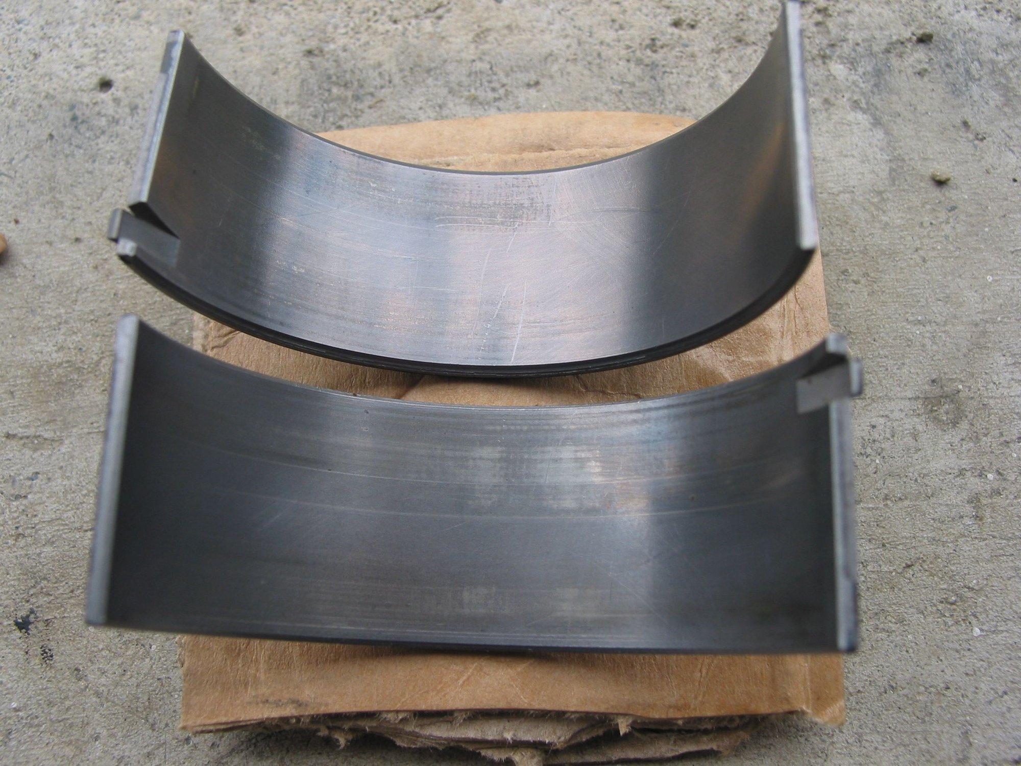
cleaned up the last of the piston & bore tops today, removed sump and No 6 rod bearings.
Most of the piston tops still had an arrow drawn on facing the front of the engine still visible.
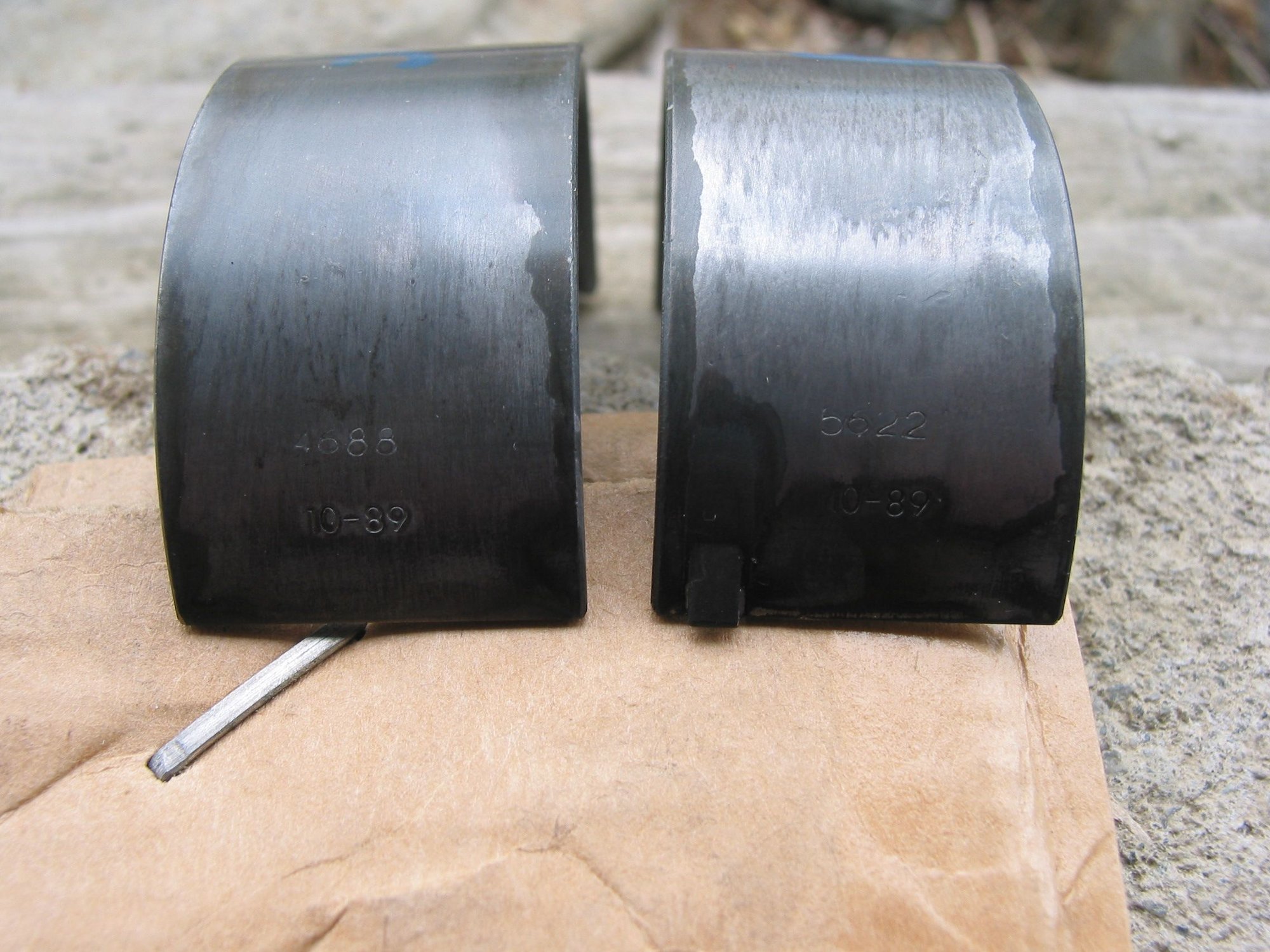
Hear is a photo of the no 6 shells. Really hard to get a good photo.
Bearing surface seemed really soft - put a scratch in one with my fingernail when feeling for roughness.
Bearings are stamped with "std' and a date 10 - 89 and with another number that doesn't match - any idea what these might mean? My WAG is shell thickness Identification.....
Anyway, I used the plastiguage method to get a quick determination of bearing clearance - around 0.045mm.

 09-10-2021, 07:21 PM