When you click on links to various merchants on this site and make a purchase, this can result in this site earning a commission. Affiliate programs and affiliations include, but are not limited to, the eBay Partner Network.
Auto equipped 928's drive shafts want to pull the crankshaft out of the engine. The harder you drive them the more they tug on the crank. There's a joke in there.
The effects show up in the flex plate. It bows toward the rear. When you release the flex clamp the flex plate returns to its original flat position.
It also relieves the pressure on the crankshaft.
Measuring crank end play is the best way to know the health of your thrust bearing.
Others will correct me or add more flesh to the answer
The flexplate bows towards the front, trying to push the crankshaft out of the front of the engine.
There are two possible causes for this to occur. (At this point in time):
1. This occurs because the torque tube shaft twists more, as it ages. The additional amount of twist "shortens" the driveshaft very quickly when torque is applied, which pulls the shaft out of the flexplate.
When the shaft relaxes, it lengthens slower than it twisted and does not push itself back into the flexplate.
The result is that the flexplate bows towards the front. (This is the most common layperson's accepted theory, but has some severe "issues", when science/physics is applied.)
2. As the car ages, the rubber mounting parts on the harmonic absorber (in the rear of the torque tube) deteriorate.
As this occurs, the ability for the harmonic absorber to dampen the frequencies of the torque tube shaft is reduced.
This allows the torque tube shaft to create a larger "wave", which pulls the torque tube shaft out of the front clamp.
The result is the same. (This theory was put forth by an leading expert in frequencies and harmonics. The science/physics of what is happening works much better, with this theory!)
could you explain more as to what happens to the flex plate? I have done some research and as of yet not found a fully detailed answer
When one is doing a search about a given problem I find it better to type in the problem and then add "Rennlist" from a google based search. That simply finds better and more answers than the internal search engine seems to.
The flexplate itself as its name suggests is a flexible coupling that tolerates a degree of misalignment due to the likes of body flex or torque tube flex, temperature expansion differences etc and is a very common device used on all types of rotating machinery in industrial applications to connect drivers to machines likes pumps, compressors etc etc.
During acceleration the shaft winds itself up to some extent acting as a transmission shock absorber in the process and as one can easily visualise, this is quite a harsh process and the resulting wind up in effect shortens the length of the shaft and in some cases appears to pull the shaft out of the clamp in what we assume to be very small increments. In my case some 22 years ago my S4 would develop a distinct vibration at precisely 3050 rpms and when this happened I knew the shaft had slipped. When the shaft takes a lighter load and there is less wind up the effective shaft length has increased and eventually this creates a situation where the crank thrust bearing rear face starts to behave like a disc brake. Eventually the friction becomes too much, the heat developed causes the thrust bearing to wipe, the white metal melts and upon cooling down a tad can grab the thrust bearing shell and cause it to spin in the crankcase and when this happens the bearing support webs crack and that is that. The flex plate itself is often horribly distorted and in most cases the first the owner knows aobut it is when they try to start he car and the thing will not crank as the white metal fuses the crank to the crank case. Quite conceivable that the starter motor may even cause the thurst bearing to spin in some cases.
This problem happened during my initial days of ownership early 1999 and then I knew little about what was going on other than I was concerned- then one day the 28mm shaft snapped just behind the splines. Upon fitment of a new torque tube the problem vibration stopped only to reappear after about 2 weeks of driving. A check showed the shaft slipping back about 2mm after clamp release. After this happened again Porsche then came up with the new bolt and overtorque bit that I introduced to the list. I can well believe this may be enough additional "stiction" for some examples to hold but it did not work on my 928 and I would not trust such approach.
I discussed this problem with a couple of top drawer mechanical engineering colleagues of mine and we agreed that some kind of bonding agent might do the trick. Another suggestion that emanated was that I should get hold of the new to our locale internet and look for a website that specialised in the Porsche 928 and the rest is history. Within minutes of posting about my dilemma I received a response from Mr Earl Gilstrom advising that he was about to try a solution to what turned out to be a very common problem and he was proposing to use a Loctite 290 formulation. I managed to get hold of some Loctite 270 which is similar but has slightly higher temperature resistance and we did my flexplate the day after Earl did his first attempt. The joint held firm until I lost my S4 in an accident some 5 years later. I then repeated the procedure in my current 928 early 2006 when transplanting my S4 motor into my current GTS chassis and it has held tight for the last 15 or whatever years.
The ultimate solution is to fit Constantine's wonderful clamp that is precisely what Porsche should have engineered from day one when they decided to abandon the original clamp and shim design in 1984 that works perfectly well even though it is a bit of a PITA to get right. Lots of owners have used the Loctite approach and I have personally guided many owners how to go about this. Non of the folks I have helped in this regard have ever reverted to advise it did not work- all I can say is that in my environment it has worked for over 20 years in total but I cannot say with 100% confidence it will still be holding next week.
Thank you all for allowing me to Hi Jack this thread. I will definitely inspect that area. I do need to learn about this clamp as well that is available and an upgrade.
I will confirm FredR's experience. My car was the first one where Earl G. applied the Loctite 290 to the splined connection between the flex plate and the drive shaft. I was driving this automatic transmission car on racetracks at Porsche Driver Education programs, and had several 3rd to 2nd full throttle kickdowns per lap at those tracks. We were both concerned about the 'creep' that Greg describes. We applied the Loctite, waited about 30 minutes, then torqued the new bolt to spec +10%, then let walked away and didn't touch anything for 36 hours. Then we marked the clamp/shaft with a dab of white paint. 3 years later there was NO movement of the clamp.
I will confirm FredR's experience. My car was the first one where Earl G. applied the Loctite 290 to the splined connection between the flex plate and the drive shaft. I was driving this automatic transmission car on racetracks at Porsche Driver Education programs, and had several 3rd to 2nd full throttle kickdowns per lap at those tracks. We were both concerned about the 'creep' that Greg describes. We applied the Loctite, waited about 30 minutes, then torqued the new bolt to spec +10%, then let walked away and didn't touch anything for 36 hours. Then we marked the clamp/shaft with a dab of white paint. 3 years later there was NO movement of the clamp.
Gary
Gary,
Did not know the first 928 that Earl worked on was your 928!
I do know we have known each other for a rather long time. It was somewhere around May 1999 when we first tackled this issue. In the same discussion I opined that the clamp design was like the kick starter I had on my 1957 BSA 650 uber modified cafe racer and had no place on a high performance top end GT like the 928. I commented on how a proper clamp should have a taper locking mechanism and then Constantine contacted me offline and confided how he was developing such a clamp and we shared some thoughts.
I often wonder how many other examples get the vibration warning I got. I know one of our friends a few years ago now acquired a 928 and did some great work from scratch. He commented on how it had a strange vibration at 3050 and I opined I had the same issue and paticularly so just before the shaft snapped.. I was accused of being somewhat alarmist. The chap completed his work drove off down the road and about a mile from home his shaft snapped!
It should be remembered that Porsche designed the front flex plate clamp to be used in concert with some pieces at the front of the drive shaft to locate the front flex plate in a very specific relation to the flywheel. Those pieces were removed in 1984 but the front clamp was never redesigned to work alone in keeping the drive shaft clamped against movement. This was a mistake that was never rectified in the 928 automatic driveline for the remaining run of the 928 model.
Porsche did know of issues with this drive shaft movement afterwards and tried fixing it by enlarging the diameter of the drive shaft from 25mm to 28mm. That still did not fix the problem and Porsche gave the 928 auto drivelines another problem with 28mm drive shafts shearing at the necked points to the splines since the splines areas were kept at 25mm. Porsche should have enlarged the front and rear clamps to accommodate a 28mm spline.
Porsche also sent out a service bulletin that TBF problems after a TT change were due to the improper installation of the TT, shifting blame of their failed designs and changes to the servicing departments.
Also it should be remembered that most auto TTs only have two bearing units in them, which leaves a long length of the drive shaft unsupported and uncontrolled against wind up, another failed design in my opinion. The vibration dampener has nothing really to do with controlling this movement.
Whatever way one chooses to look at this problem the one thing that appears to be constant is that if the slippage does not happen or is stopped, the problems we typically see do not occur. The torque converter bearings do not fail in 50kmiles, the 28mm shafts do not snap, TBF does not occur, torque tube bearings do not go for a walk. If the 28mm shaft was inherently weak Bill Ball's 89 S4 could not possibly have covered 300k miles with no intervention.. The Porsche engineers who designed the original concept obviously saw a potential problem and mitigated for it. Whoever was responsible for dropping this design feature and did not beef up the clamp should be taken out and shot.
Porsche must have known full well what was going on and they did absolutely nothing to stop it - not too difficult to understand considering they were all but bankrupt in 1992. Twenty years ago the local customer service representative of the day, a chap from a Middle Eastern country of dubious reputation, upon getting a mouth full of grief from me post failure of my 28mm shaft on a 90 S4 with 50k miles on the clock, had the audacity to tell me he could break the shaft in 5 minutes to whit I replied that might be possible if he were a complete and utter tw*t! Basically he was intimating the shaft failed because of the way it had been driven. There was nothing wrong with the original 25mm shaft - they modified it and in the process created an additional point of failure that happens if and when the clamp slips.
Now this is really going far afield from the original intent of this thread, but while we're here an interesting fact to consider is 25mm drive shafts do not seem to suffer such fractures or shears as often.
This is even in 928S4 automatics (Porsche used 25mm drive shafts in MY87 into MY88 TTs) with the same engine outputs, TT configurations (two bearing units and vibration dampener) and front flex plate slippage as those with the 28mm drive shafts used into the 928 GTS versions.
In fact, I have only seen one such shear in a 25mm drive shaft in the 20+ years I have been involved in rebuilding TTs.
This is not meant to argue against your point, just something to consider when discussing the 25mm and 28mm drive shafts.
Constantine,
I fully agree with you- the 28mm shaft created a stress concentration point behind the splines and I concluded that shaft failure is an unintended consequence of the 28mm shaft design that happens as and when the clamp slips - no problem at all as long as the correct alignment is maintained. 20 years ago folks were blaming the taper design for the problem but this was grossly unfair- it was the victim not the culprit. If the 28mm shaft were fundamentally defective there is no way examples could or would cover 300k miles- they would all fail at some point in their lifespan. There may be a reduced life but obviously whatever it is, it would have to be greater than 300k miles and I can live with that.
For reasons we have never been able to pinpoint some models hold and some do not irrespective of whether they are 28mm equipped or 25mm equipped- 25mm shaft models experience TBF but I have never come across one that experienced a shaft failure- it may have happened but I simply do not know of such. Models equipped with 28mm shafts that have not experienced clamp slippage do not have such problems or so our experiences suggest. I can well believe 28mm shaft models are more susceptible to clamp slippage as the shaft is not going to experience the same degree of wind up and maybe this creates more "******" on the clamp. I also concluded that shaft breakage may also be a blessing in disguise in that it acts like a frangible link and in some instances might just prevent onset of TBF. The 3050 rpm vibration I reported took place at 2mm to 3mm of clamp slippage- that is not enough to cause TBF that takes more like 10mm of slippage or so I conccluded. As to why some 28mm shaft models experience TBF and not shaft failure like the original GTS engine in my current 928 frankly I have no idea.
The damper thing is something of a canard or so I suspect. My reading of the book Projekt 928 suggested that the damper was a fix for a NVH problem- i.e. comfort [i.e. noise] related not mechanical damage concern related- the damper was fitted as a result of extensive prototype testing. Had the original torque tube design been kitted out with your super bearings I reckon it is a good bet the damper would never have been needed- i.e. it was a bandaid solution. As you have pointed out previously, no torque tube revamped with your super bearings and no damper has ever had a problem be they with 25mm or 28mm stock shafts - neither has any torque tube you revamped kitted with new 25mm shafts.
Where it does get interesting though is there was no such thing as a 28mm shaft when this NVH testing was done originally and I often wonder whether they did similar tests before introducing the 28mm shaft. Had they done so one wonders whether they might have found some other dynamic going on that.they did not bargain for.
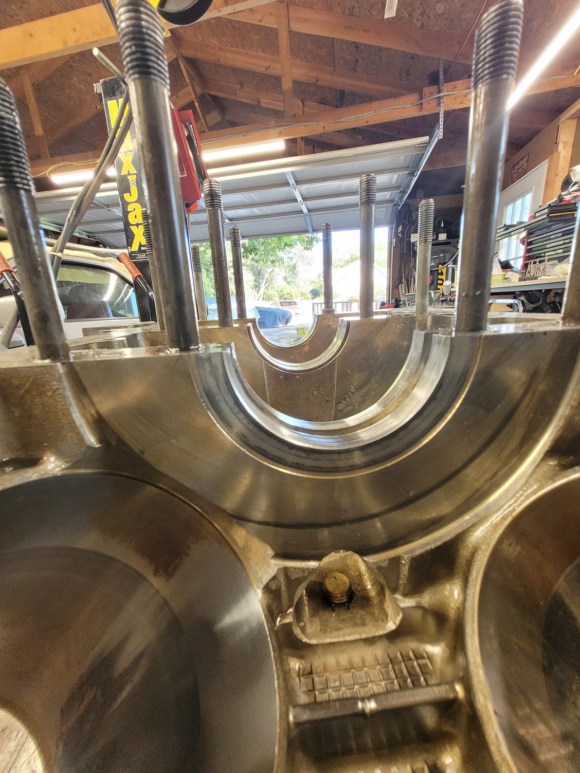
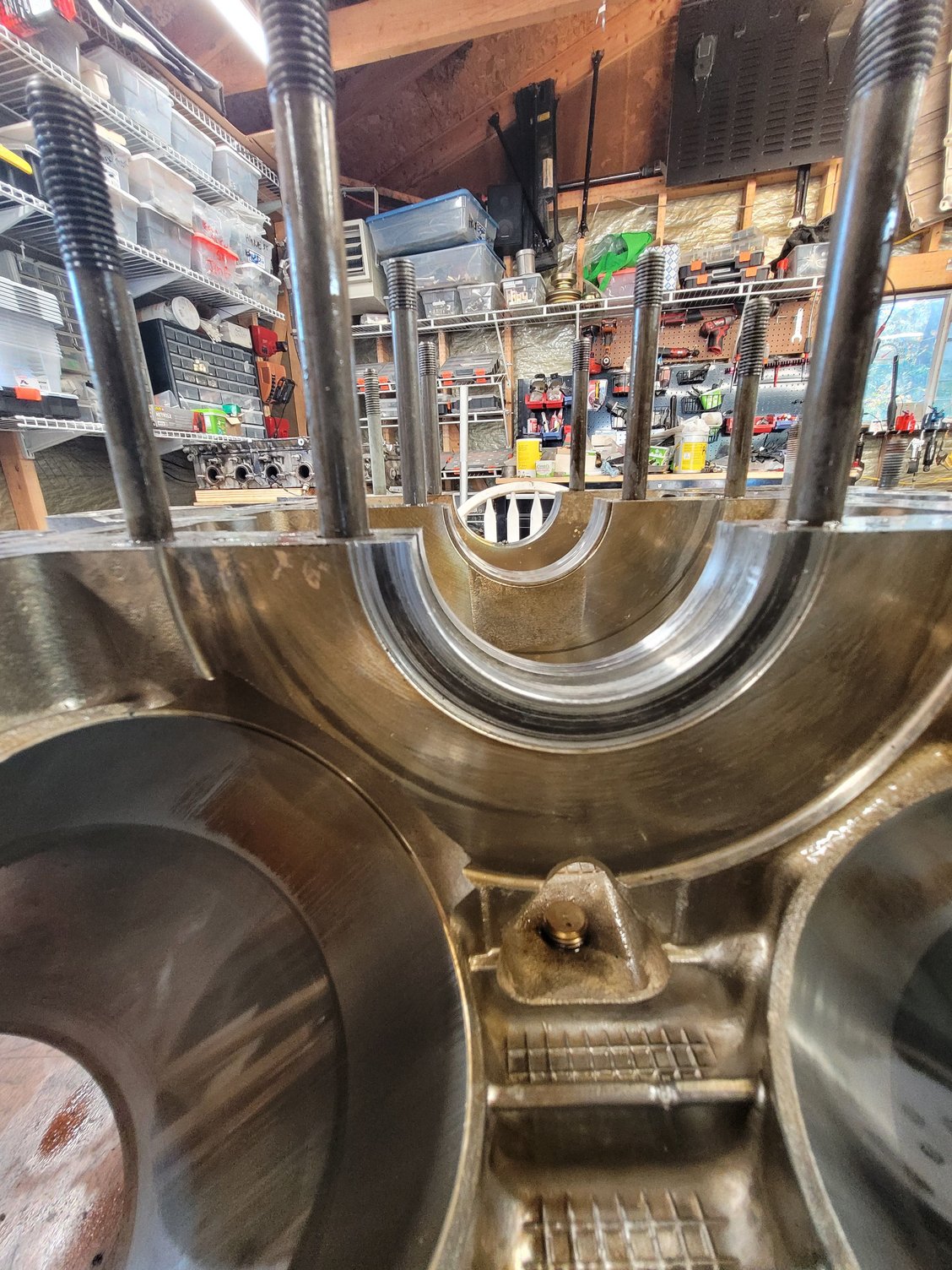
What is the dimension of the crank thrust bearing to thrust bearing faces as a matter of interest?
Theory says the white metal should wipe first followed by the copper on the thrust bearing. The spec for end float limit is 0.4mm. You reported a measured 0.75mm but most of that is on one side only. I do not know how much it has to lose before the thrust bearing is down to the steel substrate but I presume that when the crank starts to lose metal it does so because of the friction between a steel to steel contact not steel to copper as it were.
If the engine has not spun the thrust bearing then presumably it will live to fight another day - sounds as though it must have been a close run thing..
I'll get the measurement later but here are a couple of pictures.

 10-06-2021, 06:24 PM