When you click on links to various merchants on this site and make a purchase, this can result in this site earning a commission. Affiliate programs and affiliations include, but are not limited to, the eBay Partner Network.
So, in the past a mechanic might have found excessive end play and welding the the driveshaft to the coupler was the cure. Even cheaper than Greg's solution.
Which works great, as long as the little spot weld on the stock clamp doesn't break.....which is a common occurrence.
Once the tiny spot weld breaks, the R clamp pulls the stock clamp right along (with the driveshaft) to the rear.
Same result....the shaft is pulled to the rear and the thrust bearing gets ruined from the forward pressure.
It's a "patch"....and not as good as one of the other "patches".
Like I'm trying to subtilly tell everyone (above) the only completely "bullet proof" (and cheap) solution is to do what Porsche did for the early cars.....fit the circlip, the special washer, and shim the washer correctly.....on the front side of the flexplate.
The shaft absolutely can not pull out of the flexplate, without ripping the circlip off, which is impossible to have happen, with the special washer in place!!
If you don't have a shaft with a circlip groove, it's most likely a 28mm shaft.....which should be changed to a 25mm shaft, anyway.
The really amazing thing about this entire flex plate/torque tub shaft migration problem is that the original engineers knew this was a problem, so they fitted pieces to prevent this from happening. Once the flywheel changed shape (4 speeds), the "solution" was difficult to install, so "the solution" was left out....even though PET shows the pieces that were the solution all the way through the end of 1995. And unlike every other part that gets used and then discontinued, there's no "up to" with a serial number....PET makes it appear like the pieces were there, when the cars left the factory.
It's like the guy that was supposed to install the pieces stuck them in his pocket and took them home, everyday, so he didn't have to install them.
So, in the past a mechanic might have found excessive end play and welding the the driveshaft to the coupler was the cure. Even cheaper than Greg's solution.
Isn't there someone that promotes welding on the intermediate plate for a 5 speed manual?
"Weld up the intermediate plate on a manual, weld the shaft to the clamp on an automatic."
Crijkes- has Donald Trump gone and cancelled Newton's third law of motion?
The tack weld makes makes no difference to the clamp's structural integrity flawed as it may be. The tack weld is only there to locate the clamp over the split sleeve at the desired position- nothing else or so I would think.
The stock clamp compresses a split sleeve that in turn clamps onto the splines of the shaft. Common sense should tell us that whatever compressive forces are applied to the shaft are also applied from the clamp to the sleeve. That the shaft splines slip relative to the sleeve is an established fact but in 20 years of interest analysing this problem and continued success in solving it for no more than a few cents worth of Loctite, I have yet to read of anyone reporting the clamp having slipped relative to the split sleeve. The rear clamp is identical in most respects and that floats to permit engagement of the bolt through the detente in the shaft that fixes the rear location of the shaft relative to the torque converter and that should tell one that the spot weld is not needed for joint integrity.
Up front the Ritech clamp relies on the grip between the clamp and the sleeve to prevent differential movement of the shaft. That the tack weld will make a further contribution is fact but the notion that Richard's design requires integrity of that weld to function correctly does not seem logical to my way of thinking. Maybe Roger can get Richard's take on this as only he knows what he did or did not consider during his design process.
If the success of the Ritech clamp depends on the integrity of that tack weld then I would be somewhat concerned if I was relying on it to protect my motor from TBF - however I would hope that is just not the case.
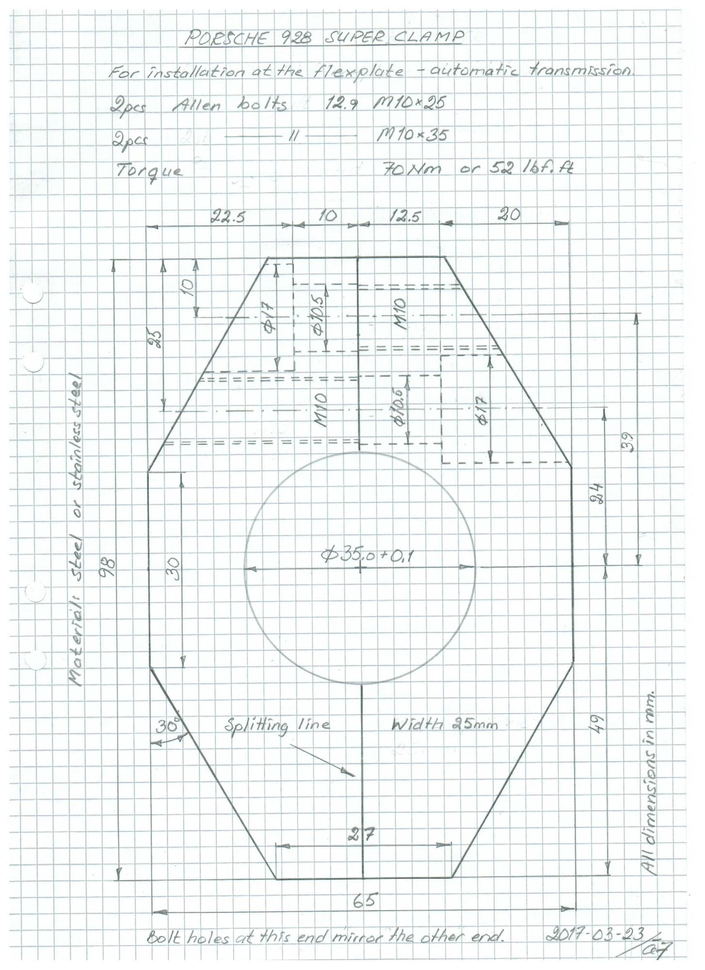
For the one who wants to fabricate his own Super Clamp here is the drawing. The clamp is machined in one piece and then divided along the splitting line.
�ke
Crijkes- has Donald Trump gone and cancelled Newton's third law of motion?
The tack weld makes makes no difference to the clamp's structural integrity flawed as it may be. The tack weld is only there to locate the clamp over the split sleeve at the desired position- nothing else or so I would think. Perhaps - but the weld's function changes once the R clamp is added - it becomes load bearing.
The stock clamp compresses a split sleeve that in turn clamps onto the splines of the shaft. Common sense should tell us that whatever compressive forces are applied to the shaft are also applied from the clamp to the sleeve. That the shaft splines slip relative to the sleeve is an established fact but in 20 years of interest analysing this problem and continued success in solving it for no more than a few cents worth of Loctite, I have yet to read of anyone reporting the clamp having slipped relative to the split sleeve. Agreed - until the R clamp is added. Prior to this, there is no axial force applied to the clamp. It couldn't slip without the weld breaking and what would break the weld - there are no significant forces on it? Once the R clamp is added, different story. The rear clamp is identical in most respects and that floats to permit engagement of the bolt through the detente in the shaft that fixes the rear location of the shaft relative to the torque converter and that should tell one that the spot weld is not needed for joint integrity.
Up front the Ritech clamp relies on the grip between the clamp and the sleeve to prevent differential movement of the shaft. That the tack weld will make a further contribution is fact but the notion that Richard's design requires integrity of that weld to function correctly does not seem logical to my way of thinking. Maybe Roger can get Richard's take on this as only he knows what he did or did not consider during his design process. Assuming the weld is not there, the grip between the clamp and sleeve is of a similar type to the grip between the sleeve and driveshaft - friction. Since it is well known that the friction between the sleeve and driveshaft is not sufficient to hold the driveshaft in place, why would you assume the friction between the clamp and sleeve (with the R clamp installed) would be? Granted, with the R clamp in place (with no weld) the amount of friction has increased as both interface surface's friction is additive. It may not be enough to hold the driveshaft in place by itself (without the weld). I don't know. I also don't know what has more friction, the splined driveshaft to sleeve interface, with all it's nooks and crannies and torque forces applied or the smooth clamp to sleeve interface, but I suspect it is the former. Therefore, to my thinking the tack weld is the critical element that the R clamp relies on to perform.
If the success of the Ritech clamp depends on the integrity of that tack weld then I would be somewhat concerned if I was relying on it to protect my motor from TBF - however I would hope that is just not the case.
Question to the moderators, can this thread be made into a thread at the top of the 928 forum?
There is so much great information in it, complete with videos, pictures and "family friendly" dialogue from multiple sources, that discusses a very important and still unknown reality for many 928 automatic (and 5- speed) owners, I think it is worthy of that status.
If not, this thread will get buried again and a few months later another thread will pop up re-hashing the same information.
I'm not against the idea, but for someone who's a 100% noob wandering into this topic, this thread, like most on this topic, could be quite confusing.
I'd much rather see someone who's really good at documentation put together a summary, including those video's and detailing all the fixes etc... so one post & done for someone to read.
Any volunteers? We could just add that summary to Roger's OP that way everything one needs to know is up front and still part of this thread.
I agree that the weld will become an integral part of the structural support once the R clamp is installed, but as for failure of that weld: I believe it is a near impossibility that it could fail in a way that would render the R clamp ineffective. I you will notice the weld is on the rear side of the clamp. being on the rear side the clamp means that the weld is in compression. With the weld in compression the chance of failure is virtually 0. Yet even if the weld were to fail, the chances that the failed weld would render the R clamp ineffective are equally low, since the only way the clamp could migrate aft would be if the weld failed precisely along the surface plane of the coupler. With a fracture plane above the coupler there would still be a mechanical limiter of the clamp since it would butt up against the remainder of the weld still affixed to the coupler, and if the weld fracture line dipped into the coupler the clamp would essentially have a tooth that locked it into the divot in the coupler again preventing the aftward movement of the clamp.
I agree that the weld will become an integral part of the structural support once the R clamp is installed, but as for failure of that weld: I believe it is a near impossibility that it could fail in a way that would render the R clamp ineffective. I you will notice the weld is on the rear side of the clamp. being on the rear side the clamp means that the weld is in compression. The weld is basically in shear with the axial load on the driveshaft pulling the clamp rearward. With the weld in compression the chance of failure is virtually 0. Yet even if the weld were to fail, the chances that the failed weld would render the R clamp ineffective are equally low, since the only way the clamp could migrate aft would be if the weld failed precisely along the surface plane of the coupler. With a fracture plane above the coupler there would still be a mechanical limiter of the clamp since it would butt up against the remainder of the weld still affixed to the coupler, and if the weld fracture line dipped into the coupler the clamp would essentially have a tooth that locked it into the divot in the coupler again preventing the aftward movement of the clamp. I suspect if the axial force was large enough to break the weld in the first place, while simultaneously overcoming both areas of clamping friction, the remnants of the weld would not be enough to hold the clamp in place - but this is just speculation on my part
I mostly agree with your points and observations. I'm not suggesting either clamp is ineffective. I was just pointing out that both operate differently, and that the R clamp relies on the weld at the clamp to perform.
I'm not against the idea, but for someone who's a 100% noob wandering into this topic, this thread, like most on this topic, could be quite confusing.
I'd much rather see someone who's really good at documentation put together a summary, including those video's and detailing all the fixes etc... so one post & done for someone to read.
Any volunteers? We could just add that summary to Roger's OP that way everything one needs to know is up front and still part of this thread.
Also, that summary would be added to the FAQ.
Thanks Hacker - my main reason for posting was to warn of the possibility of TBF and how easy it is to check before (preferably) or post purchase.
I will come up with a procedure with the video that defines the check. Also the various ways to prevent it it - pros and cons.
__________________
Does it have the "Do It Yourself" manual transmission, or the superior "Fully Equipped by Porsche" Automatic Transmission? George Layton March 2014
928 Owners are ".....a secret sect of quietly assured Porsche pragmatists who in near anonymity appreciate the prodigious, easy going prowess of the 928."
I mostly agree with your points and observations. I'm not suggesting either clamp is ineffective. I was just pointing out that both operate differently, and that the R clamp relies on the weld at the clamp to perform.
I have contacted Richard the Ritech designer for his thoughts relative to the original clamp weld and its possible effect on the Ritech.
Not wander to far off the topic, but I've always thought we should celebrate 9/28 each year by performing health checks on our cars. Crankshaft end play could be one, fuel line inspection another. Basically, an annual PPI.
Richard's clamp is an auxiliary device preventing slippage of the shaft in much the same way as the original design with shims and circlip did. Under normal circumstances when fitted there is no axial load on the Ritech device and it only comes into play if and when the clamp falls short in grip and the shaft then tries to pull through.
The stock clamp for whatever reason, in some instances simply cannot hold the shaft- why this is the case no one really knows for sure but what we do know is that by increasing the clamping force the TBF phenomena is avoided altogether. The stock clamp in the majority of examples seems to hold but some [significant] percentage do not. When the stock clamp compresses over the splined sleeve there is no axial load component on the clamp itself but the compressive stresses that pinch the splined sleeve are more than capable of restraining any axial load imposed on the clamp body by the Ritech device. That there is a small weld present is one thing but it will not be taking any load unless and until the clamping force compressing the clamp body to the splined sleeve is overcome and that is just not going to happen. In that context the weldment should be seen as a bonus and nothing more.
Common sense should tell the informed mind that the inadequacy of the stock clamp is marginal on the cases that do fail and by extension, the increment of additional restraint needed is relatively small.. What you choose to believe is up to your good self but the engineering mind should understand that the "tack weld" positioning the clamp relative to the sleeve is irrelevant.


 06-13-2019, 07:28 PM


 George Layton March 2014