When you click on links to various merchants on this site and make a purchase, this can result in this site earning a commission. Affiliate programs and affiliations include, but are not limited to, the eBay Partner Network.
Ok had a few minutes to start checking things and here is what I have found.
1). I have continuity from the sensor to the plug on the pod on the blue-yellow wire.
2) i also have continuity to ground on that wire.
So....somewhere that blue and yellow wire is making contact with ground.
I believe eve the best way to isolate will be to start by disconnecting �G� at the CEP and checking for continuity between the CEP and the cluster and then from the CEP to the sensor to see which side the short is on.
from the current flow diagram, it appears that the plug for g feeds the cluster and the socket in the CEP is what is coming from the engine bay - am I correct?
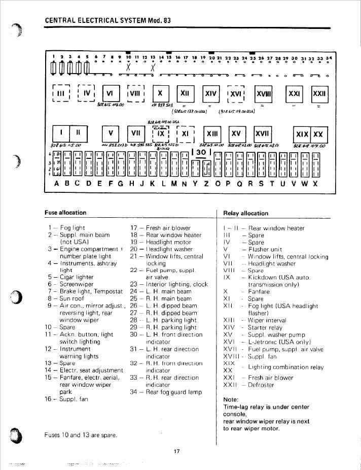
Dr. Smith, You are on the right track. You are correct that a logical way to test the continuity and to check the wiring is one "section" of the wiring path at a time. All with the battery disconnected. Working from the gauge to the sensor in five "sections" I believe this is correct. Check your diagram: 1. Pin on back of gauge --> male pin (or foil) on the instrument cluster. (Plug on drivers side, pin #11 in a row of 2-13 pins.) 2. Female #11 on plug at instrument cluster (via blue/yellow wire coming out of it) --> female #4 at 8-terminal G plug ("G4)" at CEP. 3. Male on 8-terminal plug at G4 (via gray wire on back of the CEP) ---> male at P4 on CEP. (You should lower the CEP panel down and inspect the back of the wiring for anything unusual. eg. black/burnt). 4. Female connector at P4 socket via blue/yellow wire --> 14 - pin connector near battery jump post, female socket #3. 5. 14-pin connector male pin #3 ---> female terminal at your sensor. You have a wiring diagram. These might help as well if you don't have them. (CEP fuse/relay/plug diagram. 14-pin connector chart.) Jason
Great advice above. I double check fuse charts I see posted for 80'-83' because they are usually incorrect - as these are and caused the previous owner of my car and me serious headaches with the fuel pump. No fault of yours at all, Jason.
Use this chart
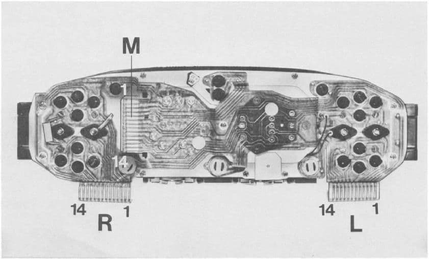
This may help with the instrument cluster pin numbering.
Great advice above. I double check fuse charts I see posted for 80'-83' because they are usually incorrect - as these are and caused the previous owner of my car and me serious headaches with the fuel pump. No fault of yours at all, Jason.
I absolutely should include the caveat that the charts/diagrams and the wiring paths that I've used are not my creation and "your results may vary."
(Why I suggested "check your diagram")
It is amazing how different some of he diagrams and actual wiring can be.
I like that cluster pic...been looking for one of those.
Jason
so I broke the circuit down as much as possible. Interesting to note that there is a second blue/yellow wire on plug G that sends signal to the mixing motor for the HVAC. I was hoping this would be the culprit but I don�t believe so.
Disconnected the following:
G plug
Six pin connector in console
plg on mixing motor with blue/yellow wire
instrument panel connector.
Here are the findings:
1). Male of plug G to ground - no continuity. This leads me to think everything from the CE panel to the sensor is fine
2). Male side (mixing motor) side of 6-pin to ground: nothing
3) mixing motor connector to ground: nothing
4). Female (harness) end of 6-pin to ground - continuity
5). Instrument panel plug to ground - continuity
so both leads from the plug side of plug G have continuity to ground. My thought is that I have maybe pinched one of the wires when reinstalling dash or something....
so...I ran a new wire (not pulling the dash today) installed in plug G. Thought for sure that would eliminate any possibility of the factory wire being grounded out.
reconnect battery and turn the key...gauge takes a second (does not move up a tad at all on ignition like the others do. After about 2 seconds - gauge pegs as before.
so I am not sure what is going on. New wire has no continuity to ground.
is there a way to test the gauge without pulling the pod? I am beginning to suspect the gauge itself.
Ok so pod is back out with gauges. Did some quick testing but need to verify that my theory of operation/testing is correct.
Using a bench power supply, have ground and +12v attached. Tried several different locations for both and everything works.
Some of the warning lamps work by simply grounding the pin for the lamp with 12v connected to a bus. Others require 12v and ground to be connected and then a separate ground be used to trigger the lamp. Everything seems to work fine this way.
so using the schematic and the same philosophy, I tried to operate the coolant gauge. With 12v and ground applied, adding a ground to the pin for the coolant gauge pegs the gauge immediately (as it does in the car) with no resistance.
i added several different resistors (from 47 ohm all the way to 1000 ohm) in between the ground and pin, but the gauge did not move. Is this the correct way to check operation? I would think that a 1k ohm resistor would have given a reading about 1/4 way up the gauge.
Am I missing something? Important to note the gauge did not peg (as it does in the car) with ANY resistor in line.
Most automotive gauges and sensors use NTC elements - negative temperature coefficient. These usually range from ~3k ohms cold down to 2-300 ohms hot. Not sure if the change is linear or not. As the gauge pegs with zero resistance, but fails with any resistance, the gauge itself would have to be suspect. Maybe try another gauge - fuel gauge reacts to near zero ohms (full) to ~80 ohms for empty. Another thought - is there a regulator/stabilizer involved that drops the normal +12V to something lower to reduce fluctuations that may be caused by changes in the batterys state of charge? Try applying say 6V to the gauge?
jp 83 Euro S AT 57k
One funny thing that I did pick up on...the lutz circuit board has continuity between pin 1 (unused) and pin 11 (the coolant gauge feed). I find that a bit odd. Neither pin has continuity with any other pin on the entire assembly.
i reached out to the lutz folks and they are going to send some ideas to troubleshoot on Monday. Just trying to stay ahead.
Well I am glad to report that the issue with my coolant gauge is fixed. If I could fully explain it all I would but here is what I learned...
I mentioned that I had replaced my circuit film with the Lutz circuit board replacements and that did not solve the issue.
In the process of diagnosing this time, I still cannot explain exactly what happened but here are my thoughts:
1. Sender unit was probably going bad/died - thus the erratic behavior and then the final straw of pegging the gauge. Could have also been corrosion on the old engine wiring harness.
2. Installed the circuit board kit. My original kit had a connection between the left and right handed boards for 'M' - for those playing along, the interconnects between the boards are labelled with letters - you just match them with wire as you install.
3. So...All wiring in the car harnessed eventually checked out. I have no explanation as to why the blue/yellow feed from the temp sender to the gauge was grounded at one point. When I went to hook everything back up, it checked fine.
4. I buggered up the circuit board by breaking the multi pin connector off of it and then tried to repair. No dice. Bryan was nice enough to sell me just the replacement for the coolant/fuel side of the panel. Here is where things get interesting...
5. Noticed on installation that this new board DID NOT have the connector for 'M'. I just taped off the wire from the other side and did not worry about it.
FOLLOW ALONG here -
1. I had noticed that the first circuit board that pin 1 and pin 11 had continuity. Pin 1 is not used (at least on US cars, or most of them) and pin 11 is the sender feed to the temp gauge. Did not think much about it since there is no wire in the harness that goes to it.
2. The trace on the old board tied pins 1 and 11 together, AND to the 'M' connector - again not present on the replacement board.
3. Reinstalled with no 'M' and low and behold everything works!
MORALS:
1. According to support from Bryan Lutz (who has been great and responsive to work with), the boards with the 'M' connector were for a rarer cluster feature only on some 83 cars. There was a tie to the speedometer in these cars that also involved the coolant gauge. Not sure what the 'feature' is, but of note - my car has a shift up indicator (that has never worked) and DOES NOT have an mpg/fuel economy gauge (FWIW).
2. Apparently, the line from 'M' to the speedometer must be shorted to ground somewhere. In removing that 'M' wire from the coolant board, it removed the short to ground and everything works normally.
3. Make sure if you are ordering the Lutz boards that you know the differences. Again Bryan was great to work with in troubleshooting.

 06-10-2019, 10:13 PM