When you click on links to various merchants on this site and make a purchase, this can result in this site earning a commission. Affiliate programs and affiliations include, but are not limited to, the eBay Partner Network.
Ok, I was advised that the previous answer was not clear. I agree so I sent another message off to Pankl for clarification. The answer has come back and I quote “It allows deformation in places you want it in order to improve contact of pin and small end bore”
So I take that to mean that the deformation that occurs under load is better controlled so that the shape it deforms to is more friendly to the small end assembly.
I think this topic is interesting in light of the various 928 rods over the years, and how they changed that same area, especially on the GTS rods where there is no h-beam connection to the small end.
Yes and No, the valves are moving only 1 mm and the ports will be adjusted in size to suit the valves. The valves are larger than stock, intake is 53.34 mm and exhaust is 41.91 mm so there is scope to place the port (the area nearest the valve) to be created (by material removal) correctly in relation to the valve position. The position of the mounting surfaces for manifolds will remain stock.
Therefore, the ports will end up with a very slight curve in them.
All that welding is an impressive amount of effort to move the guide over. I assume that an offset valve guide would not have worked?
Therefore, the ports will end up with a very slight curve in them.
All that welding is an impressive amount of effort to move the guide over. I assume that an offset valve guide would not have worked?
I might go and pick up the heads today, the body is tired of four days straight of polishing, the welding was done mainly to raise the port, the raising of the port is critical to the high lift flow. Now these cams are not really big lift but without a decent amount of headflow I won’t get to my 500 hp target number. I have one development port that flows 300 odd cfm at 0.500”, my cam achieves 0.542” nett or 13.75 mm lift and I’m hoping for 315 cfm. You just wouldn’t get that without the raised port. With the welding in the spring seat area it allows for new spring seats to be cut so a nice fit is achieved as I’m using beehive springs again for the reason of a smaller diameter as such the smaller diameter allows for a high roof in the port. Remembering that the edge of the spring seat is what cuts through or gets thin as the roof of the port is raised.
Yes the welding was a lot of work, I’m told the heads for this engine are basically straight after heat treat 0.005” out now and have a brinell hardness of 102. That’s acceptable, however the other heads for the bigger 2V engine have twisted and that is a set back and they will go on hold for a while. I have enough challenges right now.
That makes the welding almost essential, instead of just moving the valve. That flow is at 28 inches?
The effort you've put into research and testing is impressive, by itself!
With the super light pistons, rods, and crank, I assume you are going to turn this engine higher into the rpm range. What is your target rpm to make 500 horsepower?
Semi-retired, as of Feb 1, 2023.
The days of free technical advice are over.
Free consultations will no longer be available.
Will still be in the shop, isolated and exclusively working on project cars, developmental work and products, engines and transmissions.
Have fun with your 928's people!
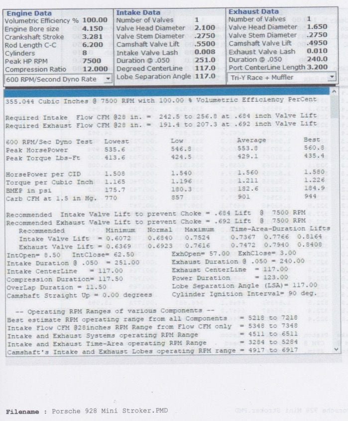
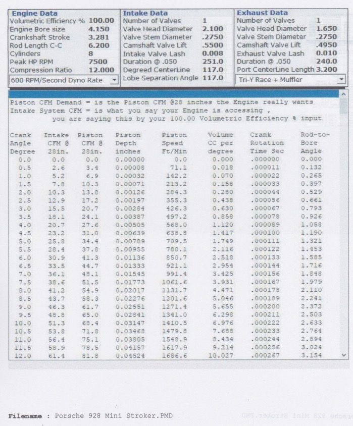
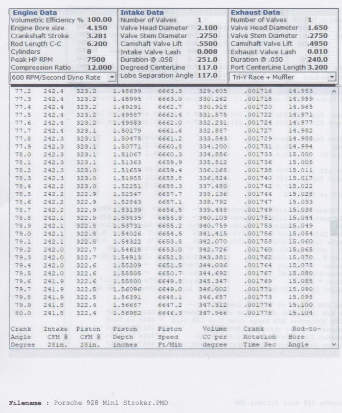
Just to explain the below tables and answer Greg's question, this is some of the Pipemax print outs, I put in 100% volumetric efficiency, to achieve that with this engine configuration the engine needs 242.5 cfm on the intake side that is with the intake manifold on and all the run to the air filter. That number is the Intake CFM which is dictated by the 100% volumetric figure I input. The piston CFM is the figure that the engine actually wants or could demand. The HP would then be much higher. I don't think there is much point at increasing the revs past 7,500 rpm as the cam is a 251/240 duration cam so its a decent cam but not big. See want you think.
The chart is showing intake air flow for different ported Porsche 2V intake ports. Interpolating tells us the flow with a 2.100" intake valve, if shrouding is held within reason, will be in the 300 CFM region at .550" or 14mm of lift. If the flow noticeably exceeds 300 CFM one can assume it depends on the high rise welded intake port. A colleague of mine building Volvo high performance engines for as long as anybody can remember used to have about the same flow with 48mm intake valves as shown on the chart. Those 2.6L four bangers with dual Weber carbs used to put out about 270 to 275 hp which tells us the goal of 500 hp for this Porsche V8 build is well within reach depending on how good the intake will be.
Ĺke
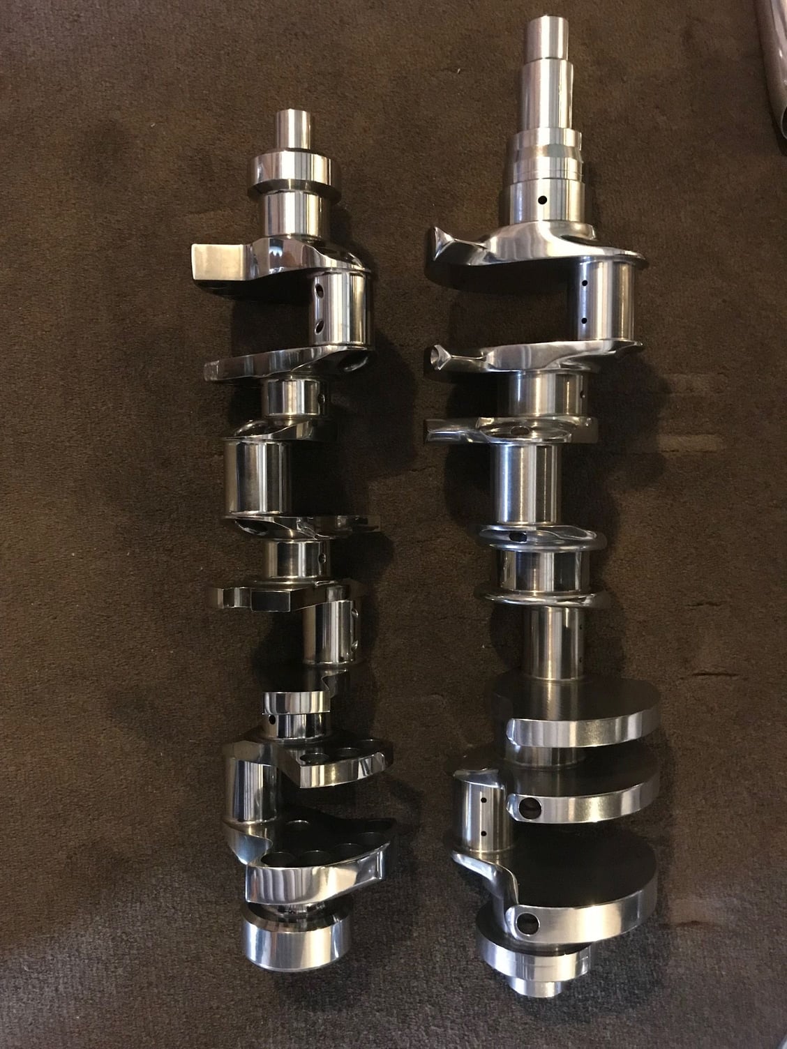
In fact that piston speed is well under stressed for the parts used, the Porsche crank will be at least as strong as the Nascar crank as the Nascar cranks are very light and have small overlaps. In fact in the article linked they are one of the reused parts, so they are one of the long life parts. For reference the Nascar cranks use 2" main journals (50.2 mm) and a 1.85" or (47 mm) rod journals versus the modified Porsche mains at 65 mm and rods at 48 mm. The rest of the parts used in this build are all Nascar parts, that is the rods, pins, pistons. Even the valve springs and valves come from Nascar suppliers. http://www.enginebuildermag.com/2017...nascar-engine/
Also in that article which is current spec the revs are up to 10,000 rpms but prior to the gear rule the rpms were regularly over 10,000 rpms and the highest rpms I heard of was 11,300. The problem was not the bottom end but broken valve springs.
Porsche 928 Crankshaft Vs Nascar Toyota Crankshaft
I calculated the metres per second and mine will be a max of approx 34 metres per second whereas Nascar regularly run 42 to 43 metres per second. So no real dramas there.
The chart is showing intake air flow for different ported Porsche 2V intake ports. Interpolating tells us the flow with a 2.100" intake valve, if shrouding is held within reason, will be in the 300 CFM region at .550" or 14mm of lift. If the flow noticeably exceeds 300 CFM one can assume it depends on the high rise welded intake port. A colleague of mine building Volvo high performance engines for as long as anybody can remember used to have about the same flow with 48mm intake valves as shown on the chart. Those 2.6L four bangers with dual Weber carbs used to put out about 270 to 275 hp which tells us the goal of 500 hp for this Porsche V8 build is well within reach depending on how good the intake will be.
Ĺke
Thanks for that write up Ake, I agree of course, if we look back at my thread which will also be updated shortly *https://rennlist.com/forums/928-foru...fold-test.html*we saw that with the 5.0 litre head flow the cfm didn't drop off very much with the intake and plenum attached. I think the flow dropped off by around 10 cfm. Now you would need to add the throttle body, *piping and air filter. One prediction I will make is that my manifold which is a ITB setup with the AT Power shaftless throttles will only lose about 15 to 20 cfm but I have no idea how much the piping and air filter will add to that loss. The air filter will be the factory air filter but at the front of the car to get the ram air effect which won't add power but will limit frictional losses. So my guess and and I stress guess is that I will lose around 30 cfm off the top number. My thoughts are that the cam is the biggest limiting factor. One test that would be really interesting would be to add the entire intake and then use a degree wheel to see how much flow we have at various degrees of rotation in relation to Pipemax numbers.*
In fact that piston speed is well under stressed for the parts used, the Porsche crank will be at least as strong as the Nascar crank as the Nascar cranks are very light and have small overlaps. In fact in the article linked they are one of the reused parts, so they are one of the long life parts. For reference the Nascar cranks use 2" main journals (50.2 mm) and a 1.85" or (47 mm) rod journals versus the modified Porsche mains at 65 mm and rods at 48 mm. The rest of the parts used in this build are all Nascar parts, that is the rods, pins, pistons. Even the valve springs and valves come from Nascar suppliers. http://www.enginebuildermag.com/2017...nascar-engine/
Also in that article which is current spec the revs are up to 10,000 rpms but prior to the gear rule the rpms were regularly over 10,000 rpms and the highest rpms I heard of was 11,300. The problem was not the bottom end but broken valve springs.
Porsche 928 Crankshaft Vs Nascar Toyota Crankshaft
I calculated the metres per second and mine will be a max of approx 34 metres per second whereas Nascar regularly run 42 to 43 metres per second. So no real dramas there.
I love what you are trying to do.
However, these two cranks have almost nothing in common, other than being shiny and they fit a V-8.
Piston speed will certainly not be an issue, with the stroke you are running and 7500 rpms.
I figured you would have to spin it over 8,000rpms to make 500hp, which is why you are using such light components.
You are correct on the crankshafts, I was really only referencing the crank pin overlap which is the main area of strength and stiffness, the material, the design, the oil drilling are all different. The oil drilling is one reason I don’t want to go too far past the factory redline. Also as mentioned in other posts the cam is only moderate and I doubt will support higher revs. My best chance at getting the power is the head flow given the limit of the camshaft.
You are correct on the crankshafts, I was really only referencing the crank pin overlap which is the main area of strength and stiffness, the material, the design, the oil drilling are all different. The oil drilling is one reason I don’t want to go too far past the factory redline. Also as mentioned in other posts the cam is only moderate and I doubt will support higher revs. My best chance at getting the power is the head flow given the limit of the camshaft.

 08-21-2018, 08:18 AM