When you click on links to various merchants on this site and make a purchase, this can result in this site earning a commission. Affiliate programs and affiliations include, but are not limited to, the eBay Partner Network.
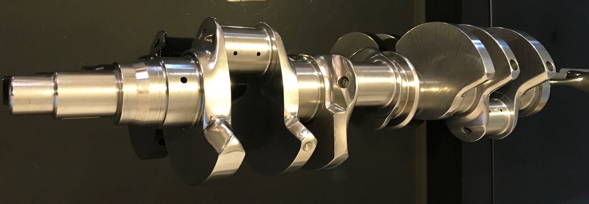
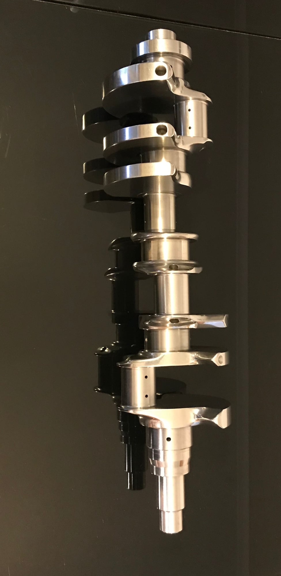
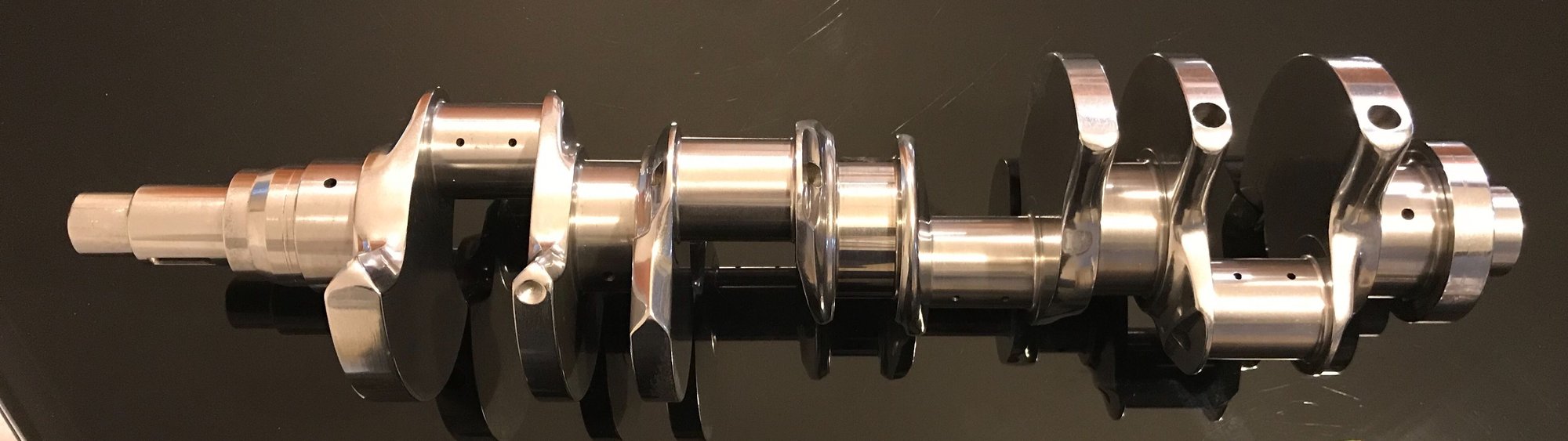
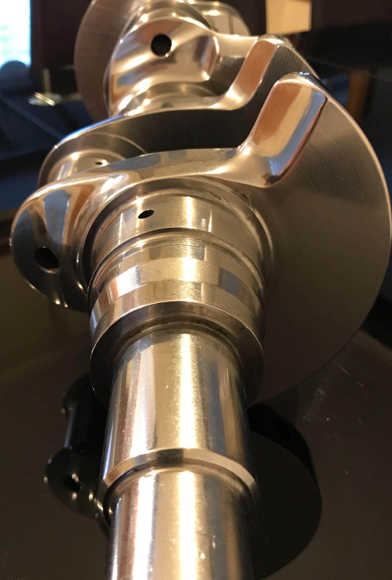
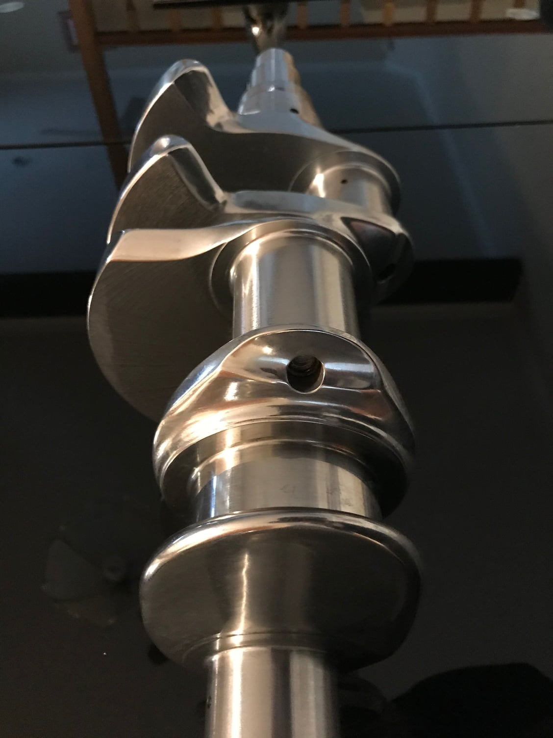
Well this is a long time in the making so thanks for your patience, I’ll just say life does have unexpected events....Anyway this project which is one of many has some progress which I think is worth sharing. The crankshaft has not been finished ground nor has the last kilo of weight been removed and this is done by mainly turning down the counterweights. This will mean that the crankshaft will be around 3 kilos lighter but the larger saving is in the rods and piston assembly where another 5 kilos is saved. So the crankshaft will go for final grind and then I will give it a light Superfinishing.
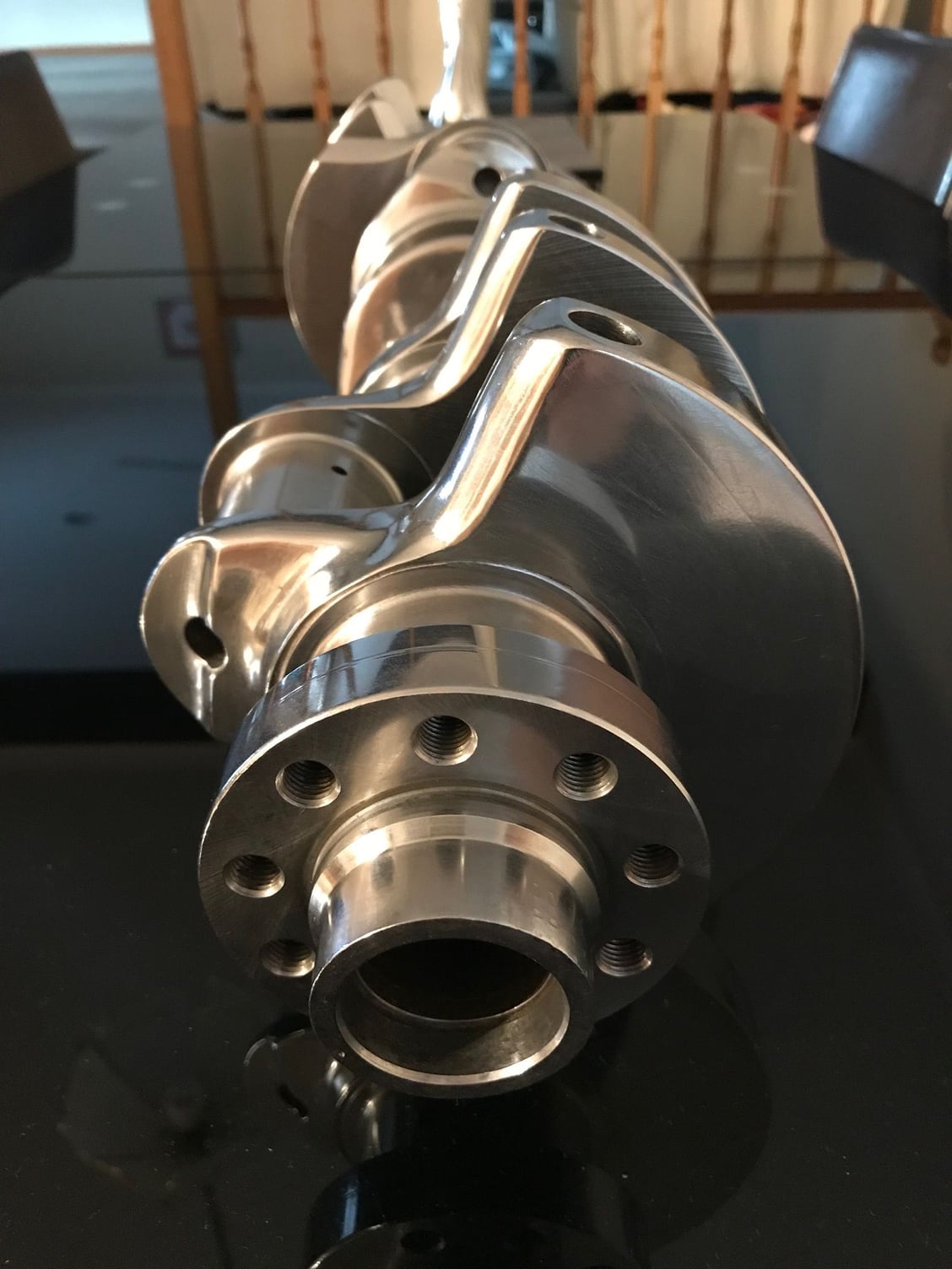
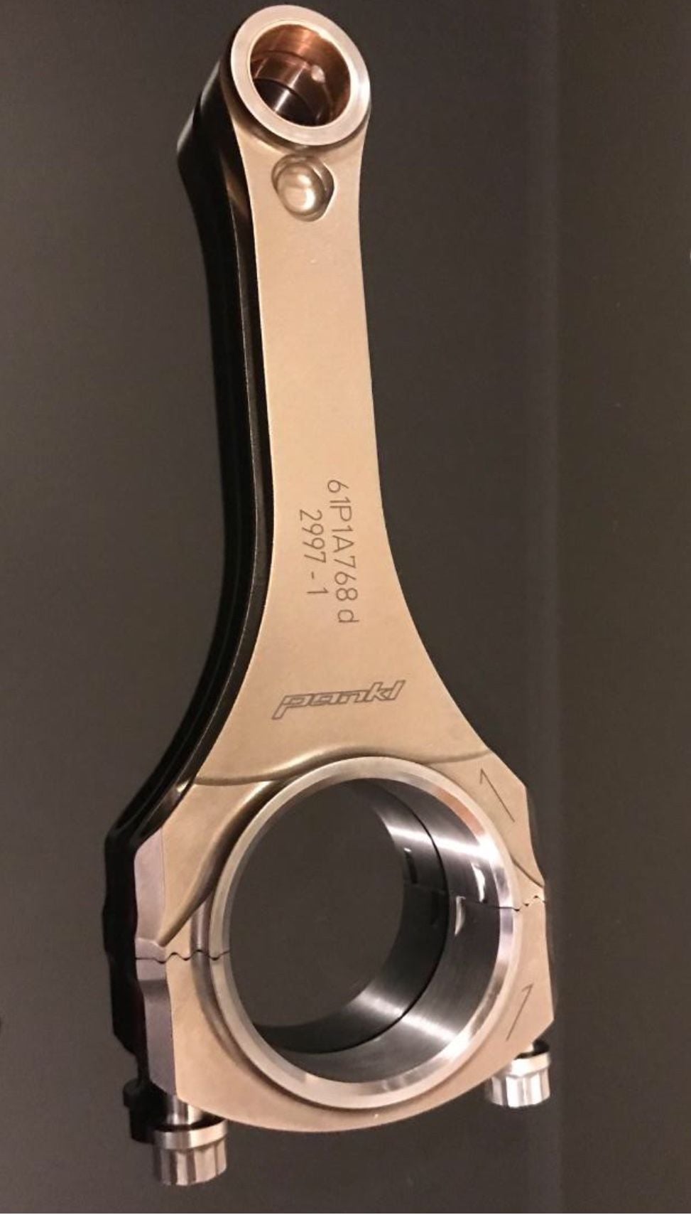
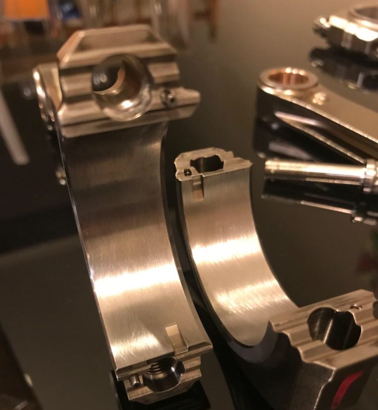
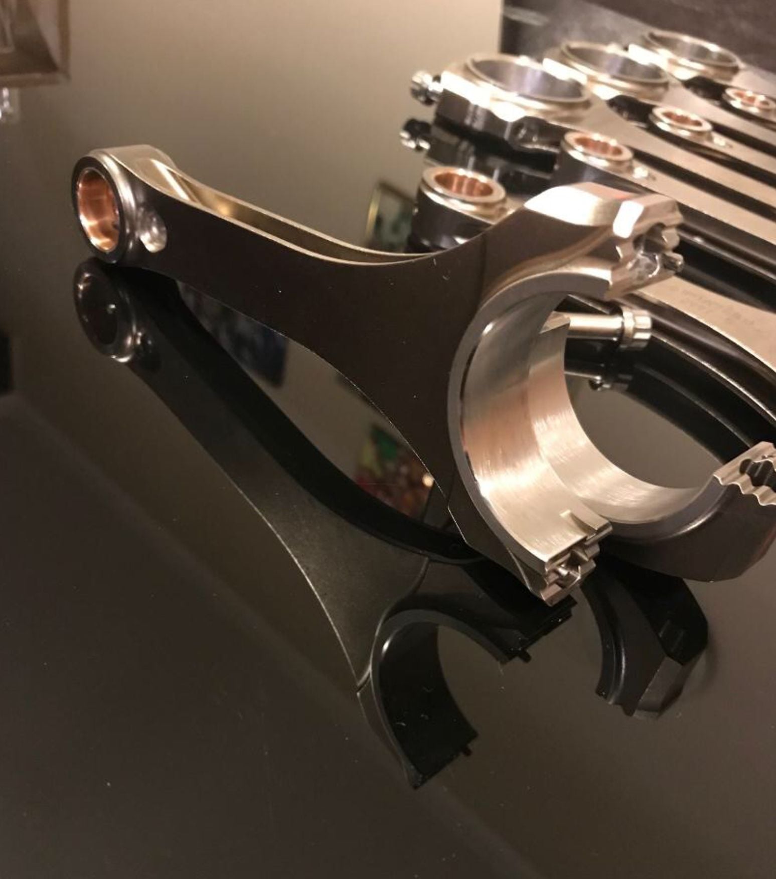
So then come the rods, 530 grams of automotive art. These are 6.2” long and use the Honda rod journal size, this is how the extra stroke has been created. The rods are to be used piston guided so I will also implementing piston squirters, they are a must for a piston guided engine, that feature of oil squirting will also keep the pistons cooler. You can see the big end cap and how it’s a saw tooth type design and the cap also has an odd shape to it. Pankl have told me they have no issues now with bearing deformation because of the cap walking under massive loads in NASCAR.
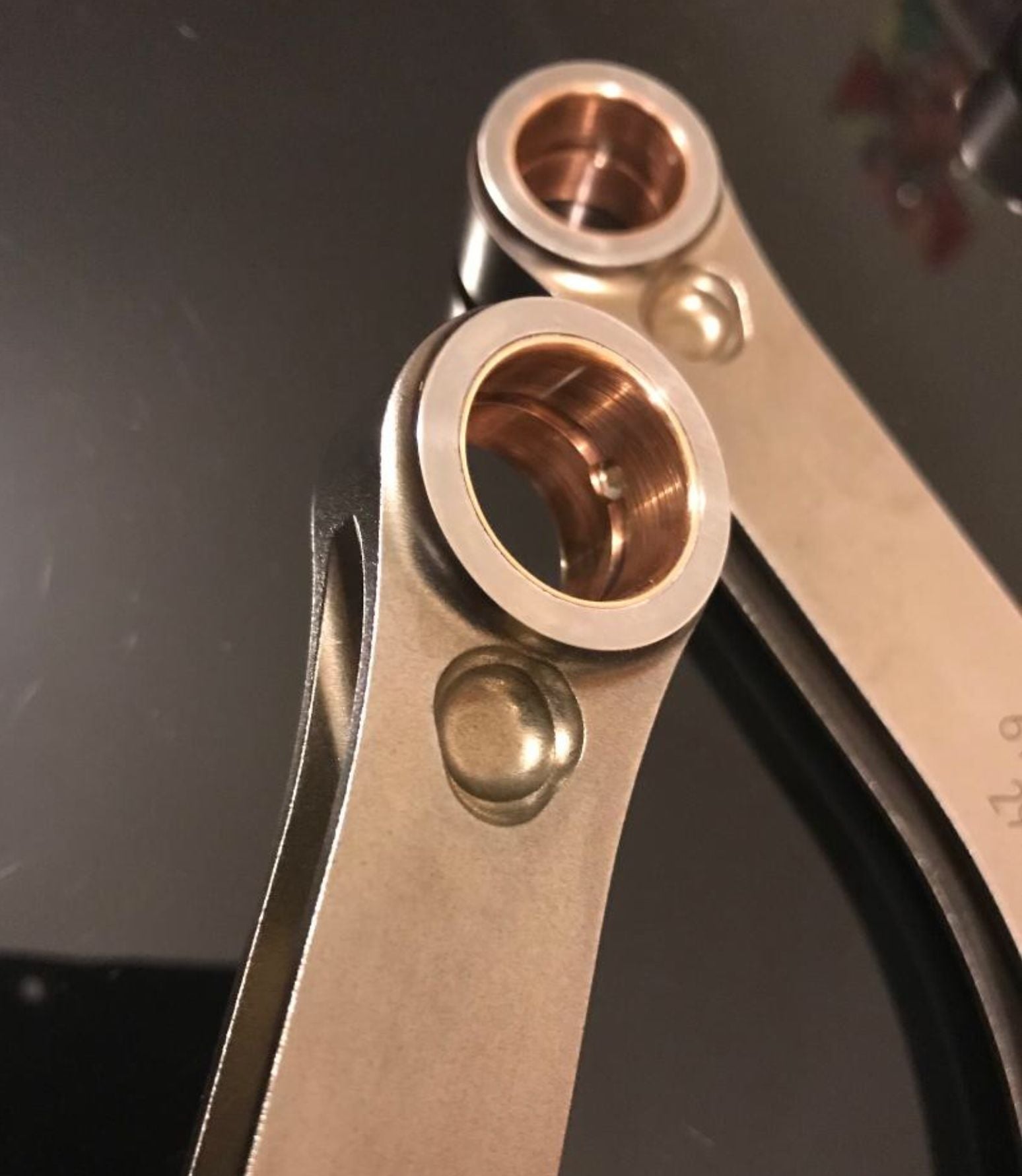
Ok I just got an answer from Pankl as to the reason for the material removal under the pin and I quote “It helps with the contact pressure of the piston pin to small end.” Now I’m taking that to mean it’s a stress relief. I do know in V8 Super Car racing in Australia the Carrillo rods were cracking just under the small end. So given Pankl own Carrillo this may be follow through research and development.
Last edited by slate blue; 08-20-2018 at 04:20 PM.
Greg, have you run the crank through your polisher, it looks so shiny? I am still questioning about the hole below the rod small end. How you ever found out why it is there? Is it a hole at both sides of the rod?
Ĺke
Greg, have you run the crank through your polisher, it looks so shiny? I am still questioning about the hole below the rod small end. How you ever found out why it is there? Is it a hole at both sides of the rod?
Ĺke
Hej Ĺke,
Yes I just got the polisher installed and you know when you get new equipment it never just works....A few teething issue to work through but it’s works well. I have polished other parts today that when they are ready I will put them up. The manifold for the 5.35 litre is not far away.
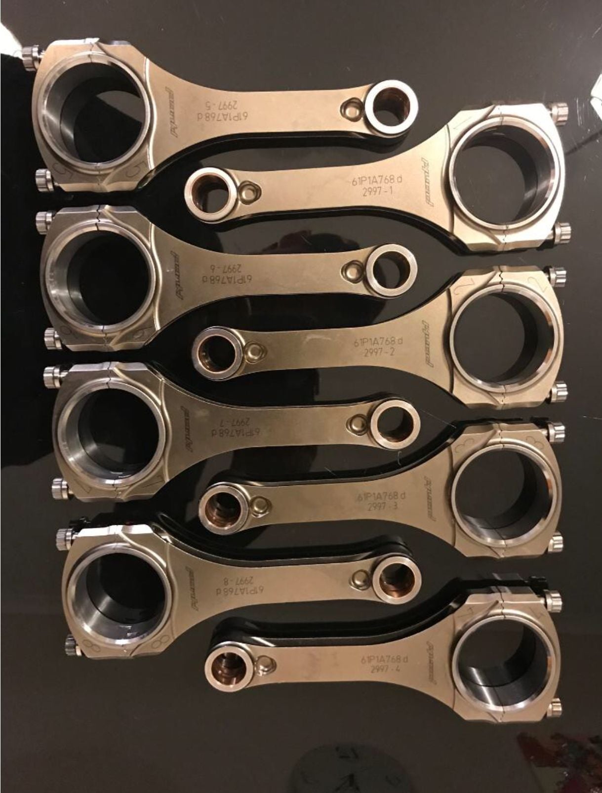
As to the the rod I haven’t followed that up with Pankl, you might get lucky soon. Yes the hole is on both sides. Incidentally the beam is thinner in depth than earlier Pankl rods, by some margin to around 4 mm. The beam is the same width though, they have spent their weight on the big end which is very robust. It would be interesting to know the weight breakdown but I don’t have the box.
Are you changing how the crankshaft oils the rods?
Has this crank been balanced for use with the lighter rods and pistons, yet?
G’day Greg,
The crankshaft has not been balanced but was run up on the machine with an anticipated bob weight, that bob weight is in the 1,500 gram range. The machinist doing the balancing said he will reduce the counterweight diameter and get it close once we have the pistons and then drill holes to fine tune the balance.
The oiling is staying standard mostly, this crankshaft has reduced bearing diameters on the mains and rods, I’m using the early crankshaft so the oil holes are smaller than the later cranks. I’m also contemplating the use of the early oil pump to deliver less oil. The engine will be dry sumped. So the oil will be of high purity as I have a oil air separator on the scavenge pump. I am yet to tear drop the oil holes. Piston guided engines have to use tight clearances on the big ends, this is the reason Pankl pay such attention to the big end strength, if it distorts it will nip the bearing, the anticipated clearance is 0.0015” to 0.0017”.
That's very cool looking and one heck of a project!
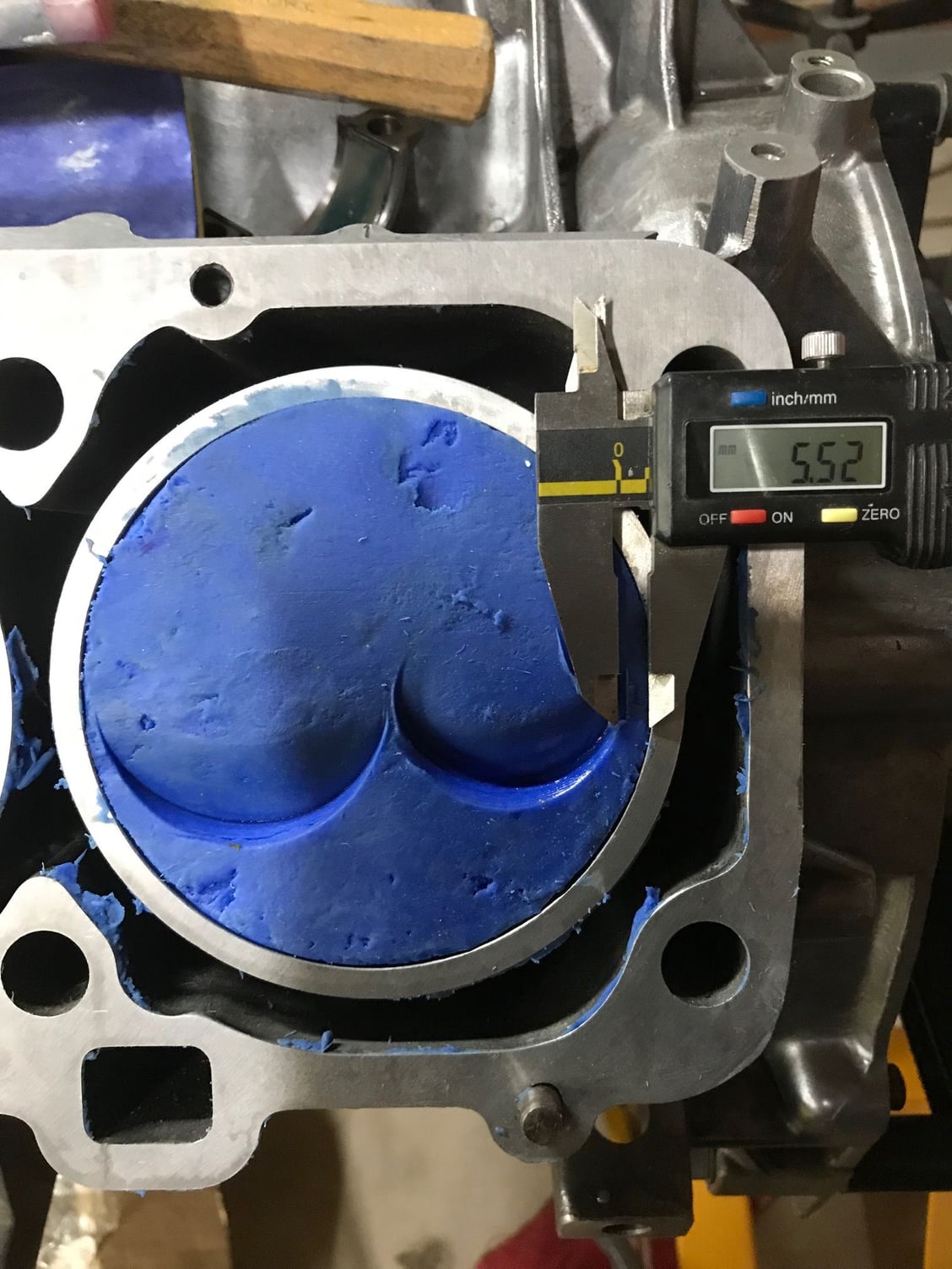
Ok so one problem you face when building high performance two valve engines is the valve placement, it’s not optimal when the valve sizes are changed. This engine is using the S2 euro heads, the valve stems will be 7 mm on both intake and exhaust. The trick to good flow is raise the roof and unshroud the intake valve, the exhaust valve flows really well which is the reason the exhaust cam duration is less than the intake cam.
Valves skewed too much to the left
So you can see from the above picture which is a 104 mm two valve engine, (52 mm intake 40 mm exhaust valves) that the exhaust valve cutout and this exhaust valve is placed a long way from the bore wall and this has the effect of shrouding the intake valve. Really instead of 5.5 mm you want something like 2.5 mm. So how do you correct this? Firstly it’s not easy, basically it’s done in steps, my first step is the bore, the block I have has core shift, if you can believe it has core shift in the right direction to move the bore so that the intake valve becomes less shrouded. I will move the bore 1 mm. You might think well you get trouble with my rods on the crank or have a misalignment problem with the rod under the pistons. Remember I am using piston guided rods, they have perfect centering under the piston and will move on the crank. However the gaps are very large at the crankshaft and the rods are 0.904” wide so they won’t hit anything. I can after the crankshaft is final ground just slightly elongate the oil holes on the crankshaft to compensate.
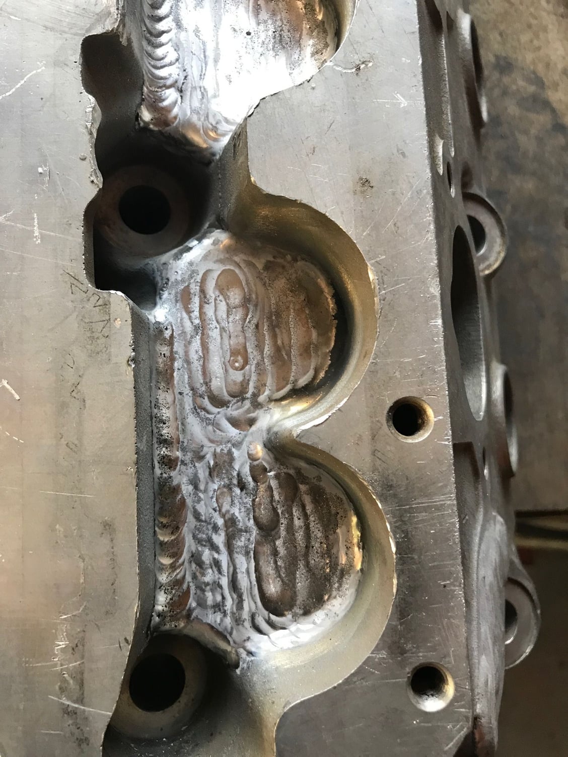
Then with the head, you can see that the heads are welded up. I will move the valves over by 1 mm. You might say wait a minute you will then have a tappet problem with alignment. No really as there is a bit of scope to slightly offset the valve to the tappet. It shouldn’t be a problem. The cams and tappets have been made so I can show them soon.
Then in the final step is the placement of the heads on the block. This is a bit more controversial, I will investigate the use of an oversized dowel, standard is 8 mm and if I use a 10 mm dowel I can move the heads 1 mm. Now the heads will move in different directions, that’s a problem but I hoping it can be mitigated. Let’s presume it can, then we have fixed the shrouding problem and now we can raise the roof of the port.
Cylinder heads extensively welded.
So the heads are welded to allow the guides to be moved and the port heights increased, by raising the roof you can run into other issues like valve spring heights, that is running out of space and the cam box then won’t fit. However I’m using a Porsche solid lifter setup advised to me by Colin Jensen many moons ago. The solid set up buys me some space which allows the whole spring assemblies to be higher in the head without running into the cam box. I am using beehive springs but I don’t have too and I may use a duel set but I already have the springs. The springs are of the same high quality as the rods which is very important when there is no inner spring just in case of breakage. These springs are made by PSI in Michigan and if you know Nascar they basically serve the whole field. They have super clean wire. Valve lift on the intake is 0.542” or 13.75 mm nett after lash.
The heads are still at the shop that tested them for hardness, they were very soft after welding. They have come back but are now distorted after heat treatment. So they need to be straightened. I am calling today my time to see how we are going. Let’s hope all is now good, they will get skimmed top and bottom after all the port and valve work is finished. I’ll update the details of the valves and hopeful flow rates when I get the heads back. To give you some idea the heads have had $1,000 of welding done to them each.
That's very cool looking and one heck of a project!
I'm excited to see this progress!
Cheers and thanks, quite a bit has been done already but some key parts are still to be made like the intake. I have an independent throttle body set up with shaftless throttles to be used and I will fabricate the runners but the plenum may well be a machined piece. I need to make the adapter plates for the throttles and the fuel rails. I am about to complete another intake system for a two valve engine but that one is for a 5.35 litre engine but it has turned out quite well and should be completed minus its fuel rails this month. I’m sure you know how much work it is to make this stuff, it’s just hours and hours of work. Nobody would ever pay for this work as it’s ridiculously labour intensive. This intake I’m about to finish has taken a bit more than a month full time to make. Figure out the cost on that.
Ok so one problem you face when building high performance two valve engines is the valve placement, it’s not optimal when the valve sizes are changed. This engine is using the S2 euro heads, the valve stems will be 7 mm on both intake and exhaust. The trick to good flow is raise the roof and unshroud the intake valve, the exhaust valve flows really well which is the reason the exhaust cam duration is less than the intake cam.
Valves skewed too much to the left
So you can see from the above picture which is a 104 mm two valve engine, (52 mm intake 40 mm exhaust valves) that the exhaust valve cutout and this exhaust valve is placed a long way from the bore wall and this has the effect of shrouding the intake valve. Really instead of 5.5 mm you want something like 2.5 mm. So how do you correct this? Firstly it’s not easy, basically it’s done in steps, my first step is the bore, the block I have has core shift, if you can believe it has core shift in the right direction to move the bore so that the intake valve becomes less shrouded. I will move the bore 1 mm. You might think well you get trouble with my rods on the crank or have a misalignment problem with the rod under the pistons. Remember I am using piston guided rods, they have perfect centering under the piston and will move on the crank. However the gaps are very large at the crankshaft and the rods are 0.904” wide so they won’t hit anything. I can after the crankshaft is final ground just slightly elongate the oil holes on the crankshaft to compensate.
Then with the head, you can see that the heads are welded up. I will move the valves over by 1 mm. You might say wait a minute you will then have a tappet problem with alignment. No really as there is a bit of scope to slightly offset the valve to the tappet. It shouldn’t be a problem. The cams and tappets have been made so I can show them soon.
Then in the final step is the placement of the heads on the block. This is a bit more controversial, I will investigate the use of an oversized dowel, standard is 8 mm and if I use a 10 mm dowel I can move the heads 1 mm. Now the heads will move in different directions, that’s a problem but I hoping it can be mitigated. Let’s presume it can, then we have fixed the shrouding problem and now we can raise the roof of the port.
Cylinder heads extensively welded.
So the heads are welded to allow the guides to be moved and the port heights increased, by raising the roof you can run into other issues like valve spring heights, that is running out of space and the cam box then won’t fit. However I’m using a Porsche solid lifter setup advised to me by Colin Jensen many moons ago. The solid set up buys me some space which allows the whole spring assemblies to be higher in the head without running into the cam box. I am using beehive springs but I don’t have too and I may use a duel set but I already have the springs. The springs are of the same high quality as the rods which is very important when there is no inner spring just in case of breakage. These springs are made by PSI in Michigan and if you know Nascar they basically serve the whole field. They have super clean wire. Valve lift on the intake is 0.542” or 13.75 mm nett after lash.
The heads are still at the shop that tested them for hardness, they were very soft after welding. They have come back but are now distorted after heat treatment. So they need to be straightened. I am calling today my time to see how we are going. Let’s hope all is now good, they will get skimmed top and bottom after all the port and valve work is finished. I’ll update the details of the valves and hopeful flow rates when I get the heads back. To give you some idea the heads have had $1,000 of welding done to them each.
If you are moving the valves, does that mean you are also moving the ports?
If you are moving the valves, does that mean you are also moving the ports?
Yes and No, the valves are moving only 1 mm and the ports will be adjusted in size to suit the valves. The valves are larger than stock, intake is 53.34 mm and exhaust is 41.91 mm so there is scope to place the port (the area nearest the valve) to be created (by material removal) correctly in relation to the valve position. The position of the mounting surfaces for manifolds will remain stock.
Ok I edited the first post under, the conrod section, Strosek Ultra was interested in the reason for that material removal and design. I have provided a quote direct from my question to Pankl. Also I do know that area is a high stress area as I have seen various FEA studies and this video was also interesting.


 08-15-2018, 04:29 AM