When you click on links to various merchants on this site and make a purchase, this can result in this site earning a commission. Affiliate programs and affiliations include, but are not limited to, the eBay Partner Network.
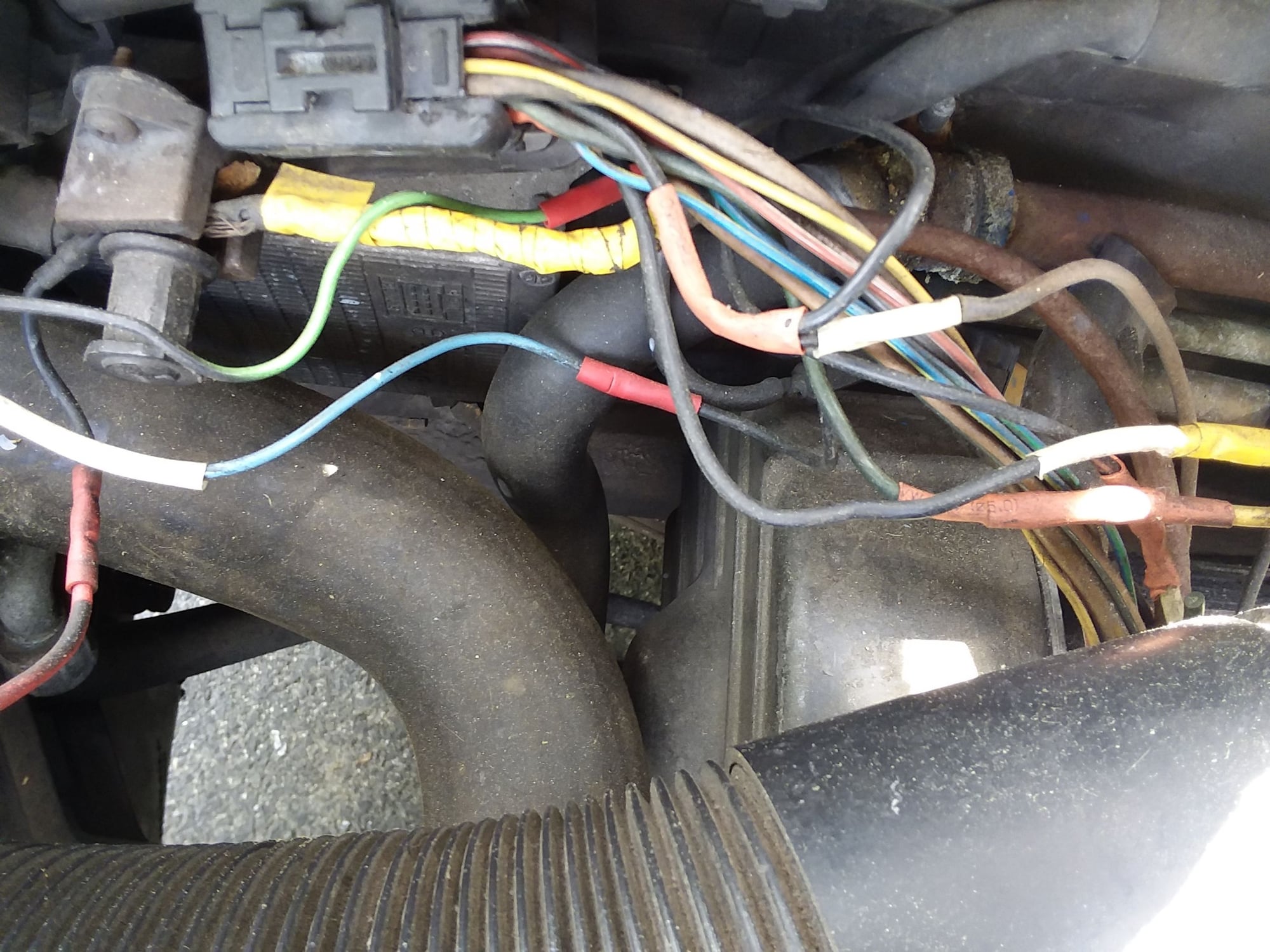
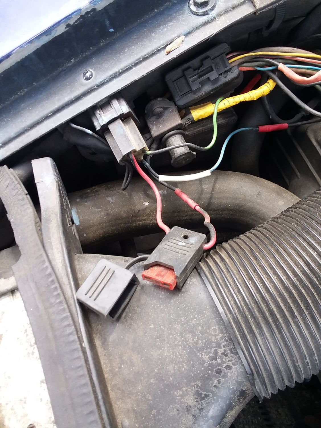
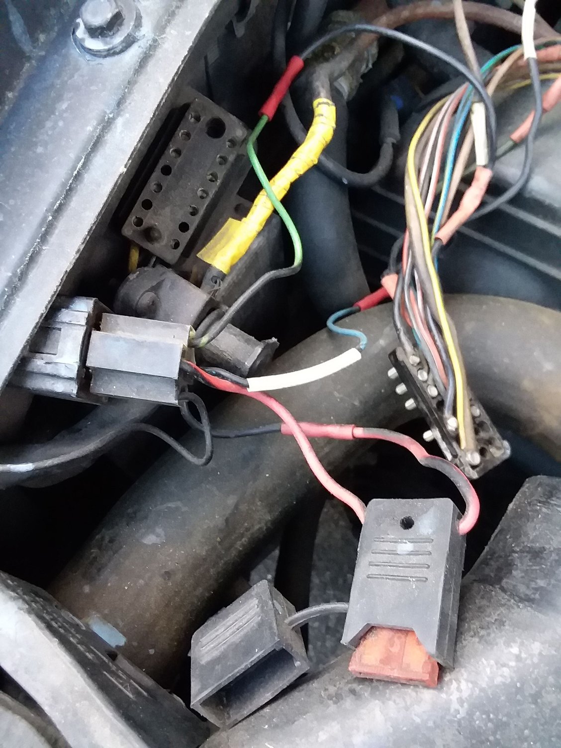
Can anyone tell me why the PO spliced a relay into the 14 pin connector??!!???? I got a new engine harness from CaptCarl for my '83 Euro 5 speed. Very Nice Product, well worth the money and wait. The PO has jumpered Pin#1 to Terminal #30 on the relay---Ter.#37 fused 10A to hot start post-----Pin #10 to Ter.#85, Ter.#86 to ground...Why would someone do this?? Is this some kind of alarm?? I guess I could just install the new harness and see if it runs. LOL
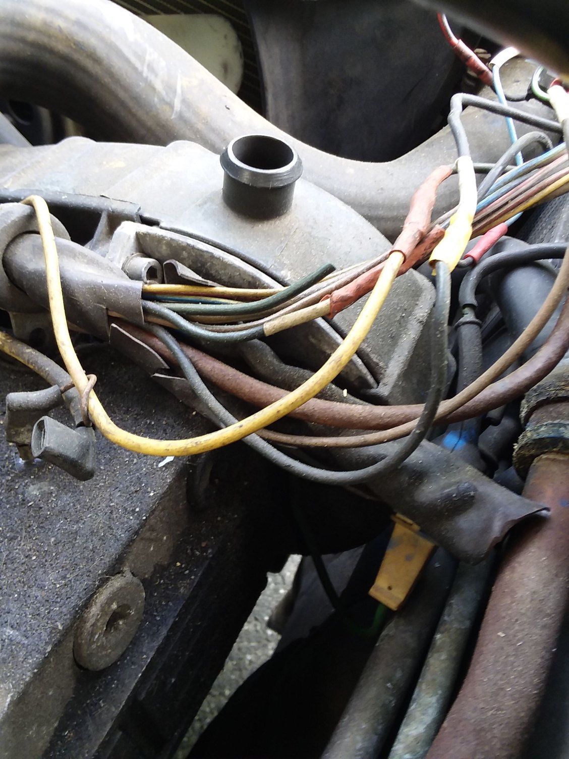
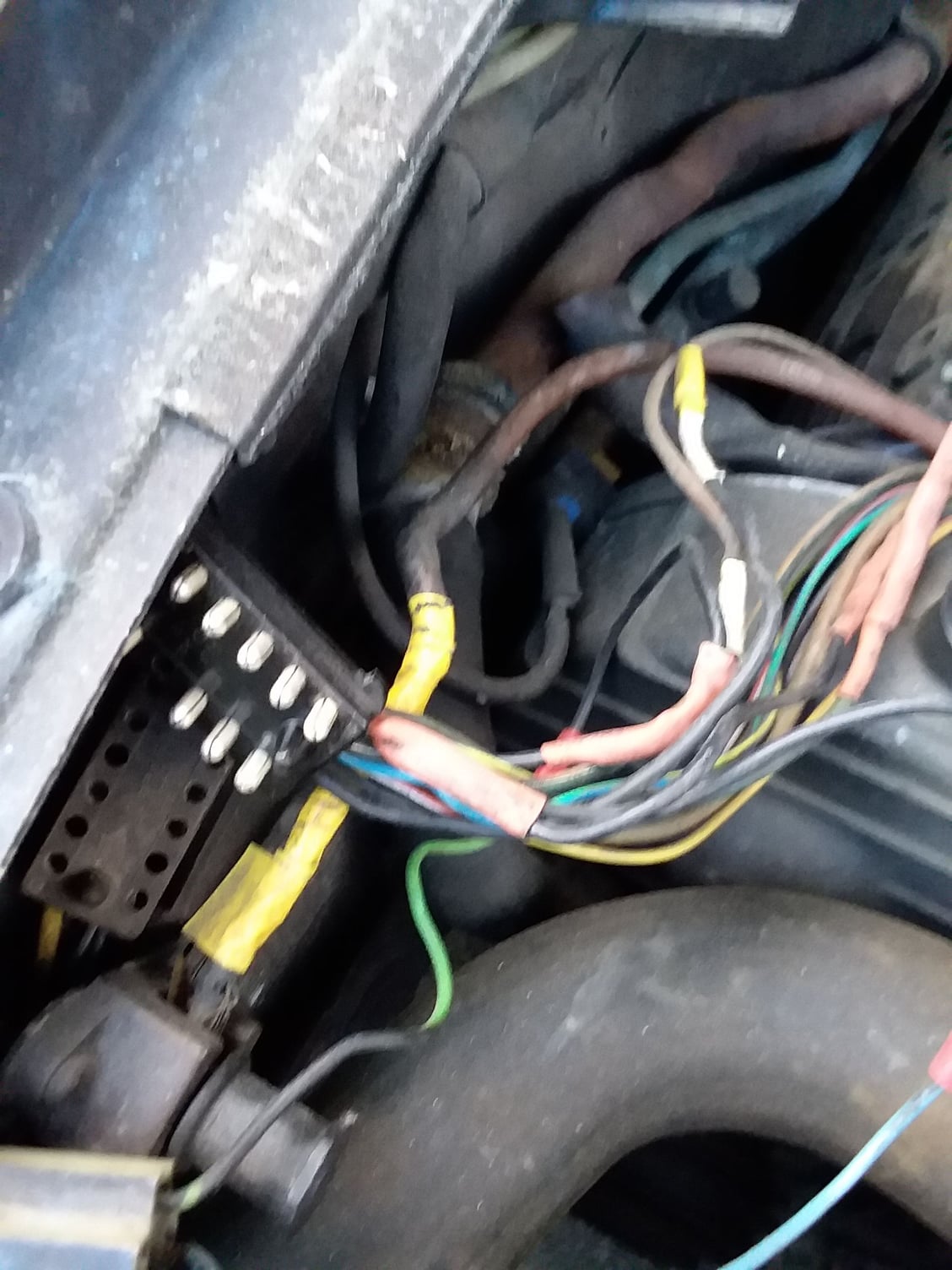
My Deep-Fried and Double Baked' wiring harness
I found this Relay/ fuse rig spliced into engine wiring harness...
This is why I'm replacing the harness---
relay hooked up to the 14 pin male block.
It seems that there's a SPST relay jumpered in.---Pin #1 to T30-> T37 fused (10A.) to hot post..., Pin #10 to T85-->T86 to Ground...
Looks as though you need to do some careful diagnostics before powering up your new harness - I suspect you have already worked that one out!
Audit the system to find out what is currently present that is not stock and then determine why it may be present. Anything present that is not stock I would dump it unless I can come up with a credible reason as to why it is present.
Last thing you want to do is toast your nice new harness. Quite unbelievable what some PO's manage to achieve.
Hello STRIKEMASTER! I don't have any wiring diagrams for Euro spec 928's. Closest I have is for an 83 US spec.
So...terminal 1 in the 14-pin connector goes to the (D+) terminal on the alternator. I believe that is the 'turn on' terminal that starts the alternator to charging. This should be a blue wire.
Terminal 10 in the 14-pin is an auxiliary temrinal from the starter solenoid. This terminal has battery voltage on it when the starter is cranking.
The way I am seeing this, when the starter is engaged, battery voltage from 14-pin terminal 10 is used to energize the relay on terminal 85, then grounded through relay terminal 85.
The relay has battery voltage from the jump post on relay terminal 87, which connects to relay terminal 30 when the relay is energized. (NOTE: This is backwards. Source of voltage should be on common terminal 30, and load should be on normally open terminal 87. Yes, I am splitting hairs...) Relay terminal 30 is connected to 14-pin terminal 1. So, battery voltage is put on the alternator (D+) terminal when the starter is cranking.
All I can figure is there is something wrong with the charging 'turn on' circuit in the instrument cluster and this relay is used to start the alternator to charging.
Take a look at this screen shot from the 1983 Current Flow Diagram. Red is 14-pin terminal 1, blue is 14-pin terminal 10.
At least your PO was kind enough to keep the connector. Mine removed it completely and soldered each pair of wires individually (obviously had more time on his hands than money) so I had to cut them to disconnect the harness when removing the engine
Follow the wire from Term #87 or whichever wire is being powered by the relay. See what the load is and then decide how to correct without using the 14-pin connector
THANKS, SKPYLE...The diagram really helps. Switched source and load connections had me a stumped too ?!?? AS a side note: Why don't they EVER print wiring diagrams in COLOR?, On fold out pages, like PLAYBOY???? It's a small thing to ask, for the price of them..Anyway thanks for the help.. Got a Ba in Electronics and I HATE working on wiring.."Plumbing with Electrons" LOL
"Another Can of Worms" Looks like I've found the worm at the bottom of the can, that holds the can with 'The Great Worm of ARRAKIS" in it..The 14 pin area in pics 1 & 2 is the way I got the car...TOASTY!! .. I got tired of breaking wires every time I worked on something and having to trace it out and splice in a new wire...Did my WP/TB and broke the wire from the oil level sender...I felt/heard it "snap!"....When I did my fuel system, I felt the wires to the 'economy gage' in the dash snap when I changed the fuel Distributor...I've had unpredictable "no crank' problems for a while...I've swapped out 2 tested starters and still have the problem, so it's not the starters...I think that during all the work on the front end and moving the wiring harness around, I've got an 'intermittent open' going to the starter. .I had changed out a starter 3 years after I got it and it ran great (mostly) for a 35 year old car with 170K miles on it. I took it to FRENZY the past 2 years and the PVGP last year.,Maybe you've seen it?.The ratty looking blue 5 speed with the sunroof..
THEN I stopped 'having fun' with it and started working on it again..New front disks and pads, shocks, and steering rack--tie-rod to tie-rod-- this past March & April... Then I started to have 'no crank' problems...
I got a box of parts with it: A new cold start injector ( that I don't need), a new fuel pump with the wrong pressure output, and what turns out to be a fairly large ceramic resistor....In posts about pod recovering I've seen it mounted to the foil on the back of the cluster...
First I'll check continuity from the female side of pin#1 to the CE Panel O8......If That side of the 14 pin block wiring is as 'toasted' as the Engine harness was, that may be the problem, If not trace back to the pod..

 06-17-2018, 09:35 PM