
Piston Mods and Machining
 01-06-2004, 09:18 PM
#1
Addict
Lifetime Rennlist
Member
Lifetime Rennlist
Member
Thread Starter
Ok guys, as usual, any and all input is appreciated.
Background: The goal is to hit the 500+Hp number using a Supercharger, like Tim, Lags, Rob and others have done. They have all done it on stock 10:1 CR and engine mgt.
I would like to achieve the same thing, but using a lower compression ratio. I want to do this to give myself that extra margin of detonation safety and perhaps in the longer term have the option of adding a bit more boost. My other reason for looking into this is the hot summer weather here in Vegas and detonation under boost. Its detonation that will kill these SC motors and blow the headgaskets..
My thinking is i can run 13 psi for example at a lower compression ratio with a greater margin of detonation safety that, for example, Lags and others are experiencing now.
Does that logic make sense??
Ok...to the meat and 'taters of it all.
To change the CR im looking at machining the Stock cast S4 100mm piston. In a previous post and using numbers that Adam B presented, my math shows that increasing the volume of the piston by 6cc will yield appx 8.5:1 CR. Im using 6cc as a max amount of material to be removed as i dont want to go below 8.5:1. In the truth of it all i think any thing LESS than 10:1 will be beneficial and a safety improvement at current boost levels being ran on the S4's.
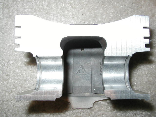
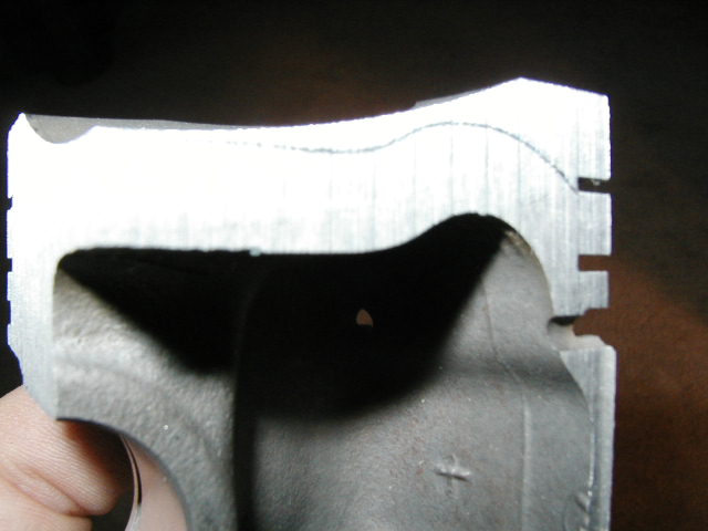
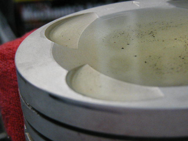
Below are pictures of an S4 piston that met its demise today at a local machine shop. Pretty revealing pictures!! I had the piston cut along the PIN axis, then again perpendicular to it on one of the remaining halves. I felt this would give me a MUCH better insight of whats going on structurally under the piston crown. A picture is worth a thousand measurements in this case!
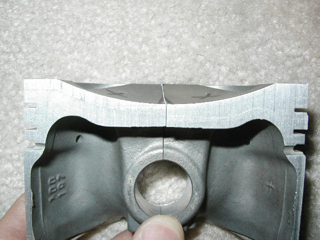
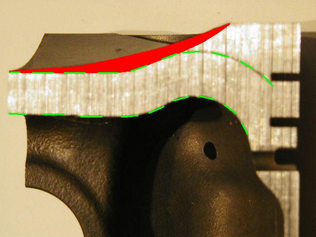
The thinnest part of the piston is at the center. .306" There fore i WILL NOT go any thinner than that anywhere on the piston. Along the pin axis there is PLENTY...PLENTY of material to work with!!! Perpendicular to it, it is a different story as you will see. The lines i have drawn on the pistons below represent a .306" profile. The red area in the picture is the material i plan on removing. As you can see im not exceeding the min thickness or changing the squish area ontop of the piston. Im only altering the SLOPE of the dish in removing material. The piston will still mate up to the head as it would originally.
The trick is...How much volume is represented by the RED area i have shown when removed around the entire perimeter of the dish!! Hmmmmm!!!
Thus what CR will i end up with in the end??
HMMMM!!
Those are the million dollar questions..well several hundred atleast. My approach will be to have the shop machine one of my scrap pistons to the way i have depicted in the pictures (red area removed) and doing a before and after CC'ing of the piston. I will obviously end up less that stock volume and 10:1 CR.... and my guess is more the 8.5:1.
Its going to come down to a bit of trial and error in the machining process i think. The good thing is, once i get it where i want it, they lock the machining in to the computer and they can spit out 8 or more Low CR pistons pretty easily with the same tolerances..
Long winded, i know...bare with me
Questions:
1) if you had any CR to choose running 10-15psi...what would it be?
.....my answer 9:1
2) What do you think about the structural integrity of the piston with the material i have shown removed??
...my answer not really an issue unless detonation occurs, which the lower CR will prevent/offset. Knowing Lags has been OK in the low teens boost wise, then i will be operating at a yet greater margin of detonation safety..
3) Any other ideas or input.
...my answer, the reason for this post!!

parallel to the pin..
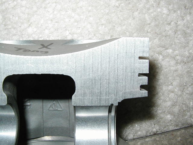
perpendicular to the pin, on center
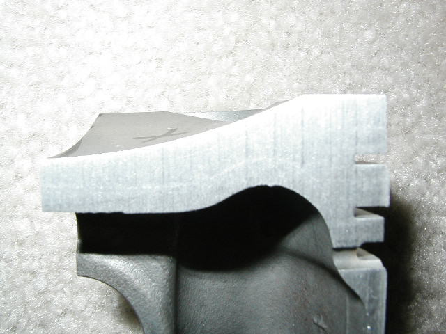
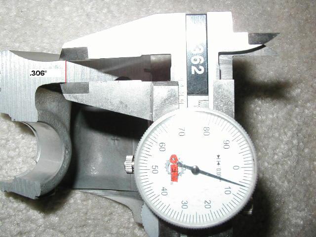
.306 profile......
material to be removed in red and the .306 porfile in green
Background: The goal is to hit the 500+Hp number using a Supercharger, like Tim, Lags, Rob and others have done. They have all done it on stock 10:1 CR and engine mgt.
I would like to achieve the same thing, but using a lower compression ratio. I want to do this to give myself that extra margin of detonation safety and perhaps in the longer term have the option of adding a bit more boost. My other reason for looking into this is the hot summer weather here in Vegas and detonation under boost. Its detonation that will kill these SC motors and blow the headgaskets..
My thinking is i can run 13 psi for example at a lower compression ratio with a greater margin of detonation safety that, for example, Lags and others are experiencing now.
Does that logic make sense??
Ok...to the meat and 'taters of it all.
To change the CR im looking at machining the Stock cast S4 100mm piston. In a previous post and using numbers that Adam B presented, my math shows that increasing the volume of the piston by 6cc will yield appx 8.5:1 CR. Im using 6cc as a max amount of material to be removed as i dont want to go below 8.5:1. In the truth of it all i think any thing LESS than 10:1 will be beneficial and a safety improvement at current boost levels being ran on the S4's.
Below are pictures of an S4 piston that met its demise today at a local machine shop. Pretty revealing pictures!! I had the piston cut along the PIN axis, then again perpendicular to it on one of the remaining halves. I felt this would give me a MUCH better insight of whats going on structurally under the piston crown. A picture is worth a thousand measurements in this case!
The thinnest part of the piston is at the center. .306" There fore i WILL NOT go any thinner than that anywhere on the piston. Along the pin axis there is PLENTY...PLENTY of material to work with!!! Perpendicular to it, it is a different story as you will see. The lines i have drawn on the pistons below represent a .306" profile. The red area in the picture is the material i plan on removing. As you can see im not exceeding the min thickness or changing the squish area ontop of the piston. Im only altering the SLOPE of the dish in removing material. The piston will still mate up to the head as it would originally.
The trick is...How much volume is represented by the RED area i have shown when removed around the entire perimeter of the dish!! Hmmmmm!!!
Thus what CR will i end up with in the end??
HMMMM!!
Those are the million dollar questions..well several hundred atleast. My approach will be to have the shop machine one of my scrap pistons to the way i have depicted in the pictures (red area removed) and doing a before and after CC'ing of the piston. I will obviously end up less that stock volume and 10:1 CR.... and my guess is more the 8.5:1.
Its going to come down to a bit of trial and error in the machining process i think. The good thing is, once i get it where i want it, they lock the machining in to the computer and they can spit out 8 or more Low CR pistons pretty easily with the same tolerances..
Long winded, i know...bare with me
Questions:
1) if you had any CR to choose running 10-15psi...what would it be?
.....my answer 9:1
2) What do you think about the structural integrity of the piston with the material i have shown removed??
...my answer not really an issue unless detonation occurs, which the lower CR will prevent/offset. Knowing Lags has been OK in the low teens boost wise, then i will be operating at a yet greater margin of detonation safety..
3) Any other ideas or input.
...my answer, the reason for this post!!
parallel to the pin..
perpendicular to the pin, on center
.306 profile......
material to be removed in red and the .306 porfile in green
 01-06-2004, 10:02 PM
#2
Tony,
Great research.....keep up the good work....
One note..your baseline of using Lags engine running boost in the teens at 10:1 compression may be off.....
Remember Adam measured a supposedly 10:1 928 engine and came up with 9.3 or so to 1......so perhaps Lags is running the same or similar lower compression at his boost levels....although the power is pretty good...
Whats a compression point worth in HP again??? Did Lag ever check his actual CR?
Wanna be safe..I'd shoot for 8.5:1 .....especially with the extra hot temps in Vegas...and then go with more boost.....
Either way......awesome undertaking...Im jealous of all these engines being built.. ;-)
later,
Tom
01-07-2004, 03:16 AM
#3
Drifting
Join Date: Feb 2002
Location: Redondo Beach, CA>>>>Atlanta,GA
Posts: 2,015
Likes: 0
Received 0 Likes
on
0 Posts
Tony,
I like the idea of removing the red area you have drawn.
Just brainstorming here........I believe it will be easy to duplicate from piston to piston with a lathe. It wouldn't even have to be a CNC lathe. Using the center depth of the dish as a reference point maybe you could simply make the dish a section of a larger hemisphere. Symeterically increasing the area of the dish without increasing it's depth.
Maybe you could use Turbo CAD to figure the volume of a hemispherical section. You would then subtract the volume of the stock dish to get the volume you are removing. Adjust the radius of the new hemisphere as needed to get the right ammount of material removed.
The piston would be clamped in a lathe with the center of the dish touching the cutting tool. The cutting tool is able to rotate left or right at a piont that is exactly the distance of the new radius from where it is touching the center of the dish. The piston is spun on the lathe and the cutting tool is slowly turned about it's pivot point cuting the new hemispherical section/dish from the piston.
With this method the only measurement that would need to be pased from piston to piston is the radius or distance from piston dish center to pivot point on tool. Very simple, just brainstorming.

As far as CR goes, better safe than sorry. The HP you are shooting for is only topped by one SCed car. It has 951 pistons (7.5:1 CR?), lives in in the cool air of Wisconsin, and has the mother of all intercoolers. Give yourself room to play by having a lower CR. Don't worry about off boost power loss as boost is there as soon as you crack the throttle at any RPM. Increasing blower discharge will more than make up for the lowered CR. For all we know Lags and my and Tims car all have 9.4:1. What CR do you presume to be starting with?
Andy K
I like the idea of removing the red area you have drawn.
Just brainstorming here........I believe it will be easy to duplicate from piston to piston with a lathe. It wouldn't even have to be a CNC lathe. Using the center depth of the dish as a reference point maybe you could simply make the dish a section of a larger hemisphere. Symeterically increasing the area of the dish without increasing it's depth.
Maybe you could use Turbo CAD to figure the volume of a hemispherical section. You would then subtract the volume of the stock dish to get the volume you are removing. Adjust the radius of the new hemisphere as needed to get the right ammount of material removed.
The piston would be clamped in a lathe with the center of the dish touching the cutting tool. The cutting tool is able to rotate left or right at a piont that is exactly the distance of the new radius from where it is touching the center of the dish. The piston is spun on the lathe and the cutting tool is slowly turned about it's pivot point cuting the new hemispherical section/dish from the piston.
With this method the only measurement that would need to be pased from piston to piston is the radius or distance from piston dish center to pivot point on tool. Very simple, just brainstorming.
As far as CR goes, better safe than sorry. The HP you are shooting for is only topped by one SCed car. It has 951 pistons (7.5:1 CR?), lives in in the cool air of Wisconsin, and has the mother of all intercoolers. Give yourself room to play by having a lower CR. Don't worry about off boost power loss as boost is there as soon as you crack the throttle at any RPM. Increasing blower discharge will more than make up for the lowered CR. For all we know Lags and my and Tims car all have 9.4:1. What CR do you presume to be starting with?
Andy K
01-07-2004, 07:34 AM
#4
Rennlist Member
Join Date: Dec 2002
Posts: 1,051
Likes: 0
Received 0 Likes
on
0 Posts
Originally posted by Tony
I would like to achieve the same thing, but using a lower compression ratio. I want to do this to give myself that extra margin of detonation safety and perhaps in the longer term have the option of adding a bit more boost. My other reason for looking into this is the hot summer weather here in Vegas and detonation under boost. Its detonation that will kill these SC motors and blow the headgaskets..
I would like to achieve the same thing, but using a lower compression ratio. I want to do this to give myself that extra margin of detonation safety and perhaps in the longer term have the option of adding a bit more boost. My other reason for looking into this is the hot summer weather here in Vegas and detonation under boost. Its detonation that will kill these SC motors and blow the headgaskets..
My thinking is i can run 13 psi for example at a lower compression ratio with a greater margin of detonation safety that, for example, Lags and others are experiencing now.
Does that logic make sense??
Does that logic make sense??
Questions:
1) if you had any CR to choose running 10-15psi...what would it be?
.....my answer 9:1
1) if you had any CR to choose running 10-15psi...what would it be?
.....my answer 9:1
2) What do you think about the structural integrity of the piston with the material i have shown removed??
...my answer not really an issue unless detonation occurs, which the lower CR will prevent/offset.
...my answer not really an issue unless detonation occurs, which the lower CR will prevent/offset.
Knowing Lags has been OK in the low teens boost wise, then i will be operating at a yet greater margin of detonation safety.
3) Any other ideas or input.
I remember you saying you had some 951 pistons. Did you cut up one of those, just to see how they compare to the S4 pistons in shape and thickness?
Originally posted by Tom. M
Whats a compression point worth in HP again???
Whats a compression point worth in HP again???
Did Lag ever check his actual CR
Originally posted by GoRideSno
The HP you are shooting for is only topped by one SCed car. It has 951 pistons (7.5:1 CR?), lives in in the cool air of Wisconsin, and has the mother of all intercoolers.
The HP you are shooting for is only topped by one SCed car. It has 951 pistons (7.5:1 CR?), lives in in the cool air of Wisconsin, and has the mother of all intercoolers.
01-07-2004, 12:18 PM
#5
Addict
Lifetime Rennlist
Member
Lifetime Rennlist
Member
Thread Starter
The more heat you can keep out of the pistons, the stronger they will be. It might be worth looking into ceramic coating the tops to help keep some of that heat out of them.
I had thought about ceramic coating but i also read somewhere that it can actually RAISE the detonation threshold.?? Anyone else hear of that?
[QUOTE]I'm sure you already know this Tony, but for anybody considering adding some boost to their car, keep in mind that compression ratio is just one part of what's involved with whether detonation occurs or not. The combustion chamber, air temperature and weather, engine temperature, breather system, octane, ignition timing, engine geometry, cams, and more can all effect it.......snipage[QUOTE]
as they say..YOU BETCHYA!! Trust me im not going too wild at all..i just want 500 HP with a bit more detonation margin for the 100+ summer season. I want to be able to put my foot down at ANY time and not worry
 Also, the research is all for the cause i suppose!
Try to get the pistons as even as possible in regards to dish shape, and volume. I'd check the combustion chambers in the heads as far as that goes too as long as you've got them off. It won't hurt to check the weight of all of the pistons before you put them in either.
Im not too worried about that, this machine shop seems pretty hitech and the guys have done similar things to other pistons in other applications. It will be all balanced before it goes back in...as far as the 951 pistons, good idea, i forgot i have 9 of them! It would be intresting to compare.
The piston would be clamped in a lathe with the center of the dish touching the cutting tool. The cutting tool is able to rotate left or right at a piont that is exactly the distance of the new radius from where it is touching the center of the dish. The piston is spun on the lathe and the cutting tool is slowly turned about it's pivot point cuting the new hemispherical section/dish from the piston.
Im going to see what other info i get from this post over the next day or two...then im basically going to "go for it" with one of the spare pistons. Wont know until i try!!!! I'll have them attempt to remove the RED area i have shown....or as close to that as they can get. Then i will CC the piston again to see what i have. They will have the intial machining in the computer so it can be adjusted later..or left the same if it truns out the way i want it. Im trying to draw up a crossectional plan for them so they can follow it. ie...remove 1mm at Xmm radius .....remove 2mm at a Xmm radius.... 3 at...etc.. With the cut up piston now i can acutally meaure that! Then again, they probably can set it all up them self in the 'puter in a matter of seconds!
Thanks again guys, Im not a high perfomrance engine guru..i dont even play one on TV. Just a shade tree mechanic that, well, works under a big tree!! HAHAHA, lots of shade! All the info i get from you all is very valuable and informative.
01-07-2004, 01:10 PM
#6
Three Wheelin'
Tony, as usual, nice pics!
Since you�re in there, you may as well take it down to 8.5:1 since let�s face it, once you get the car boosted, you will want to run more boost, and the lower compression ratio will easily accommodate the increase.
Chamber temps using 11 psi of boost, 85% ICooler Efficiency:
1083.49 at 10:1 cr
1068.04 at 09.5 cr
1052.00 at 09.0 cr
1035.29 at 08.5 cr
As usual, the �target� temp is at or below 1075 per Corky. At the very least, Corky�s 1075 provides a consistent reference point for us to fall back on.
Max boost using 8.5:1 cr and 85% ICooler Efficiency:
30 psi yields a chamber temp of 1074.55.
I would consider removing material from the 9 and 3 o�clock positions over the pin axis where there seems to be a little more mass to work with as shown in picture 1. Since you are already careful not to decrease the minimal crown thickness, there shouldn�t be a problem. If you have Corky�s �Supercharged�, he has a section addressing this very issue.
Z has two good ideas to consider regarding ceramic coating the piston tops, and to balance everything once done.
Another item to consider is to have the block studded as it provides superior clamping force over standard head bolts.
No, I never checked my actual static compression ratio.
I agree with the entire 8.5:1 assessment.
By Tony:
if you had any CR to choose running 10-15psi...what would it be?
.....my answer 9:1
if you had any CR to choose running 10-15psi...what would it be?
.....my answer 9:1
Chamber temps using 11 psi of boost, 85% ICooler Efficiency:
1083.49 at 10:1 cr
1068.04 at 09.5 cr
1052.00 at 09.0 cr
1035.29 at 08.5 cr
As usual, the �target� temp is at or below 1075 per Corky. At the very least, Corky�s 1075 provides a consistent reference point for us to fall back on.
Max boost using 8.5:1 cr and 85% ICooler Efficiency:
30 psi yields a chamber temp of 1074.55.
By Tony:
What do you think about the structural integrity of the piston with the material i have shown removed??
What do you think about the structural integrity of the piston with the material i have shown removed??
Z has two good ideas to consider regarding ceramic coating the piston tops, and to balance everything once done.
Another item to consider is to have the block studded as it provides superior clamping force over standard head bolts.
By Tom:
Did Lag ever check his actual CR?
Wanna be safe..I'd shoot for 8.5:1 .....especially with the extra hot temps in Vegas...and then go with more boost.....
Did Lag ever check his actual CR?
Wanna be safe..I'd shoot for 8.5:1 .....especially with the extra hot temps in Vegas...and then go with more boost.....
I agree with the entire 8.5:1 assessment.
01-07-2004, 01:29 PM
#7
Rennlist Member

So much talk about chamber temps....has anyone actually VERIFIED a temperature/boost relationship, or even measured EGTS?
Really good to know that at least two folks are folowing Marcus H with the use of forged pistons, NEW head gaskets, etc.
Tony, I would modify the piston differently.....sharpen the radius as you go towards the outside.....but what you have drawn is not bad. Think of a tapered beam analysis...
Keep in mind that the pistons ARE NOT ROUND and thus, if you want to chuck them up you will need a 4 jaw chuck and SOFT JAWS to prevent damage to the surface.
Coating are good...try swain.
We cut pistons on the mill...cc and adjust by hand.....all pistons are not created equal...although the cast pistons are the best for consistancy.
Marc
DEVEK
Trending Topics
01-07-2004, 02:03 PM
#8
Addict
Lifetime Rennlist
Member
Lifetime Rennlist
Member
Thread Starter
I know what a tapered beam is, they use them on Star Trek now and then, but when the word analysis gets thrown after it, or ANY word for that matter,it scares me...
Web search..
<<Results 1-15 of about 4340 containing "tapered beam analysis" NEXT >>
the first one..... HOMEWORK!!...runaway, runnnnAWAY!!
http://www.egr.msu.edu/classes/me424...aperedBeam.pdf
I found it amusing that the words "MARC" were at the top of the page!
I envy folks who can figure that stuff out!
Thanks for the reply and input Marc.
but when the word analysis gets thrown after it, or ANY word for that matter,it scares me...Web search..
<<Results 1-15 of about 4340 containing "tapered beam analysis" NEXT >>
the first one.....
HOMEWORK!!...runaway, runnnnAWAY!!http://www.egr.msu.edu/classes/me424...aperedBeam.pdf
I found it amusing that the words "MARC" were at the top of the page!
I envy folks who can figure that stuff out!
Thanks for the reply and input Marc.
01-07-2004, 04:08 PM
#10
Three Wheelin'
Tony I've done the piston, valve and CC coatings before. In fact I have now built two high Hp/Tq chevy motors that had anything metal to metal coated with something.
Polydyn
Did the piston, valve and CC coatings work? Yes and no!
Yes, it worked when in a race only motor (12-13+/1 CR running WOT most of the time), but feel short in a street motor (10+/1 CR).
The only thing about piston, valve and CC coatings are that in a street motor there is not enough heat to burn the fuel at low RPM's or at idle.
The only way I came close was to run Aviation gas with a top lube and a hot mag. drive for spark. Even then I would not call what I had "Streetable".
I would find someone in your area that could do a hardness test for you (either brinell or rockwell) on the piston your going to run to see how close to a high quality forged piston they are.
What is hardness testing?
SSI
Braddock
If you would like to find more labs or maybe one closer to you, do a Google search for " Metallurgical Lab ".
One other thing.
Why does everyone look at the pistons first to lower the C/R?
A person could take a little material off the combustion chambers, seat the valves deeper into the heads and run a thicker head gasket to lower C/R as well.
Than if you still need more (or less C/R), fly-cut the pistons!
Trust me, you want as much dome thickness as possable in a boosted motor!
Last edited by T_MaX; 01-07-2004 at 04:32 PM.
01-07-2004, 06:08 PM
#11
Rennlist Member
Join Date: Dec 2002
Posts: 1,051
Likes: 0
Received 0 Likes
on
0 Posts
Originally posted by marc@DEVEK
So much talk about chamber temps....has anyone actually VERIFIED a temperature/boost relationship, or even measured EGTS?
So much talk about chamber temps....has anyone actually VERIFIED a temperature/boost relationship, or even measured EGTS?
One of the reasons that the ceramic coating stuff is sometimes used is to try to keep as much heat in the combustion chamber doing work as possible, instead of being absorbed by the pistons, valves, and heads. Curtis' experience with coating everything may indicate that that's not the best idea for a street car that has to idle and operate at low speeds. The suggestion of ceramic coating the piston tops was mainly to try to keep as much heat out of the cast pistons as possible, to help keep them as strong as possible, and not for any possible power increases from doing it.
Originally posted by T_MaX
A person could take a little material off the combustion chambers, seat the valves deeper into the heads and run a thicker head gasket to lower C/R as well.
Than if you still need more (or less C/R), fly-cut the pistons!
A person could take a little material off the combustion chambers, seat the valves deeper into the heads and run a thicker head gasket to lower C/R as well.
Than if you still need more (or less C/R), fly-cut the pistons!
01-07-2004, 06:29 PM
#12
Three Wheelin'
Yes it will effect the squish area and the deeper valve relief may affect the Flame Front Movement, but if a person were to do all the work listed above (including machining the piston tops) with moderation kept in mind, I don't think you will see any degradation in component or engine performance.
________________________
When it comes to coating the pistons, I would not be afraid to try a thin ceramic coat on top, but keep in mind it will take more heat to run at the same efficiency. The stuff does work as designed and if done right will last a long time. Now if you coat the pistons I would not recommend ceramic coating the valves or combustion cambers at all in a street motor.
One other item that can be coated that helps a bunch to keep the heat down in the heads is to ceramic coat the exhaust ports and headers/manifolds.
In an iron block or steel cylinder motor, you can also Teflon coat the piston skirts, but I'm not sure what the outcome would be in our aluminum 928 blocks.
Last edited by T_MaX; 01-07-2004 at 06:58 PM.
01-07-2004, 06:33 PM
#13
Addict
Lifetime Rennlist
Member
Lifetime Rennlist
Member
Thread Starter
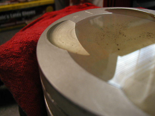
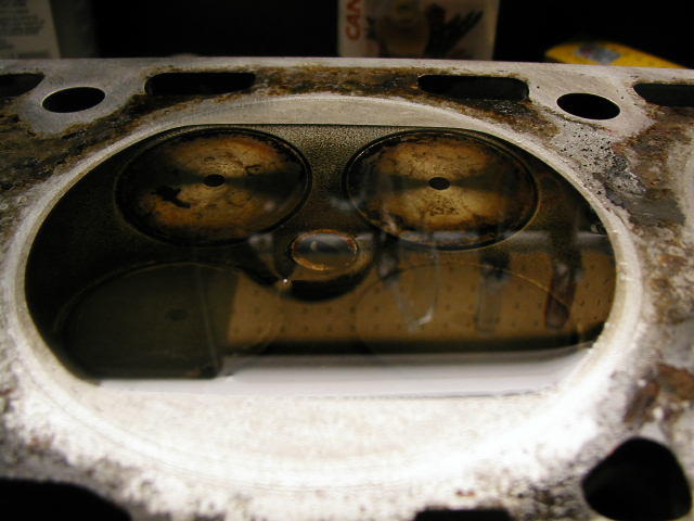
I just CC'd a stock s4 piston....24cc on the nose as far as i can tell. (did it 3 times)
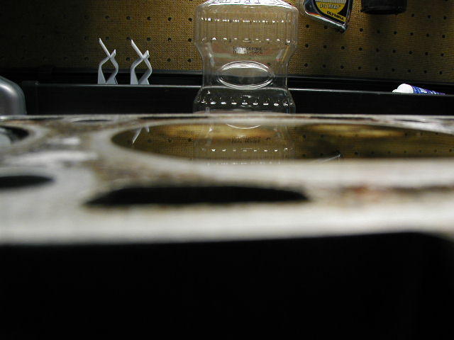
My piston is out of the car at this time. (my ref. notes say 24cc) Im trying to get a base line for the machine work. Believe it or not i ended up using Canola Corn oil and a medical syrnge. ( i have to clean up before the Mrs gets home). I tried using the plexi glass over the piston as shown in many books but it just did not work. It sealed fine but the bubbles were next to impossible to get rid of in teh corners of the valve reliefs.
I secured the piston ..leveled it with a small level and added the Canola to the dish. It worked GREAT!..before you say "surface tension"..."beading" etc....the oil does not bead up like water would, its just heavy enough to provide a perfect flat surface when it settles.. The surface i have is pristine and absolultey flush with the crown of the piston...not a drop flowing over.
The oil is yellow but the easiest way to see the amount in the dish is looking at the texture. The oil is smooth and reflects the light whereas the piston crown is grooved and does not. Its actaully VERY easy to get it to the edge.
Pictures shortly...
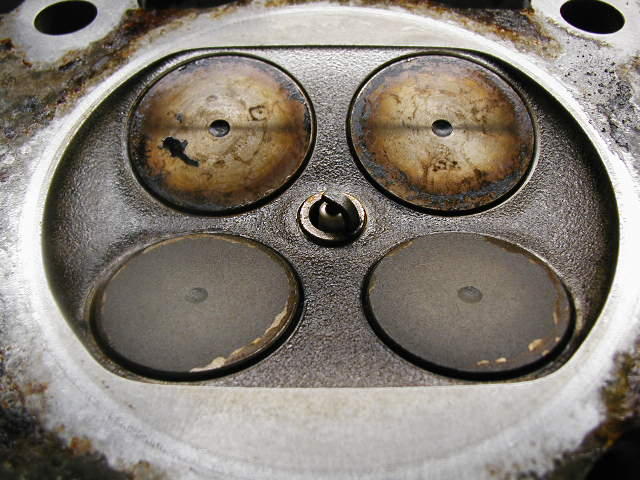
Just did one of the heads....40cc (my notes show 42...adam got 41.6)....pictures on the way
My piston is out of the car at this time. (my ref. notes say 24cc) Im trying to get a base line for the machine work. Believe it or not i ended up using Canola Corn oil and a medical syrnge. ( i have to clean up before the Mrs gets home). I tried using the plexi glass over the piston as shown in many books but it just did not work. It sealed fine but the bubbles were next to impossible to get rid of in teh corners of the valve reliefs.
I secured the piston ..leveled it with a small level and added the Canola to the dish. It worked GREAT!..before you say "surface tension"..."beading" etc....the oil does not bead up like water would, its just heavy enough to provide a perfect flat surface when it settles.. The surface i have is pristine and absolultey flush with the crown of the piston...not a drop flowing over.
The oil is yellow but the easiest way to see the amount in the dish is looking at the texture. The oil is smooth and reflects the light whereas the piston crown is grooved and does not. Its actaully VERY easy to get it to the edge.
Pictures shortly...
Just did one of the heads....40cc (my notes show 42...adam got 41.6)....pictures on the way
Last edited by Tony; 01-07-2004 at 09:56 PM.
01-07-2004, 07:12 PM
#14
Three Wheelin'
When using the "Plexi-Way", pre wetting of the plexi and item to be tested helps with bubbles 
Also, Canola Corn oil may be to thick. I use a light coat of grease around the edges of the combustion chambers to act as a seal and 3-in-1 oil for fill.
FWIW, I think you did a great job and as long as you use the same method to measure the new pistons you should at least come up with a true CC differance (or close enough anyway).
01-07-2004, 08:30 PM
#15
Rennlist Member
Sorry Tony for the engineering "terms"...you will be fine doing what you plan to do. Keep in mind that the final must be checked for each cylinder/piston/head and set to desired cc's.
Wow..measuring egts....it would be interesting to compare notes as I have been using egts for high speed in open road racing since 94. It is neat seeing the the egts stabilize at a specific load and rpm point...of course, it is "fun" watching them zip on by running up the rpms...same on the dyno, not much use since they cannot stabilize.
But the real question is regarding the much touted chamber temps and the relation to boost pressure. Has anyone have any real data on combustion chamber temps?
hi Curtis....keep in mind that the stock pistons are "coated", but by either hard chrome or by iron/tin to keep the heat in the conbustion chamber, and minimize heat loss via the pistons/rings/pin.
The polydyn coatings...skirt and piston top were allegedly used by a S Cal supercharger installer and the engine seems to run fine at idle.....but I have not done a co measurement to see if we are seeing changes in exhaust gas.
how are you doing?
Marc