When you click on links to various merchants on this site and make a purchase, this can result in this site earning a commission. Affiliate programs and affiliations include, but are not limited to, the eBay Partner Network.
thats not exactly true. i know the signs based on the spark plug appearance. usually, mild detonation will show these little ***** of aluminum way down in the insulation, so this is more obvious.... BUT, there are not the signs on the rod bearings to show the forces that could have destroyed the piston. thats the only inconsistancy i see on the the theory that detonation caused the piston failure. a better analogy about "your house burning down" would be finding a couple of cigarette butts melted in a couch and a shorted toaster. which is the cause?????? i guess we will find out. you cant deny that a offset issue posibley could be the cause.. after all that was talked about how it could be, and how "stupid" anyone would be to not use the proper offsett with the risks involved, why wouldnt it be a point of interest?
agreed. we all know the effects of detonation on a piston, but in order for those forces to destroy one, you would think there would be the normal evidence on the rod bearings. I'm trying to understand your typical failure..... Ive heard the typical failure is what we see , would be the piston stopping and the rod splitting just below the narrow end with the crank journal's travel downward. youre right though. we wont know any of these answers until we see what the top of the pistons look like. however, it would be interesting to see the offset in the other cylinders to see if they show the same offset issue, or if that was caused by the failure itself. are you not curious about that? I'm certainly no expert at all regarding failure analysis of engines, but it seems to stand out as something that could be a possible cause.
Don't quit your day job....
I think everyone, except you, realizes that the picture was taken from the right side of that rod, which hides the actual gap on the left side.
There's also side to side play in the rods down on the crankshaft (over .25mm), to keep the rods from friction welding themselves together. Unless the rods are perfectly centered on the crankshaft, when the pictire is taken, the right to left dimension at the piston can be off by thst amount.
You can relax, concentrate on something else, and quit wasting everyone's time.
These rods are made for 928 cylinder offset and are correctly centered on the pistons.
It's not a Chevy rod if it doesn't have SBC rod bearings. That kinda defeats the purpose.... yea didn't think that one all the way through
The most successful motor Mark Anderson ever campaigned had rods that were 100% to spec 928 except lighter & stronger units, still using 928 off the shelf rod bearings. Lasted how many years, how many races.....only blew when the intake failed.
So again, I go back to like page 3 - I cannot fathom why anyone is still building strokers with chevy parts when the stock bearings were proven to be reliable in the hardest driven 928 engine in history.....and in Todd's 1,000+hp twin turbo.
IMO Strokers built with Chevy rod bearings are done so to save $$$. You can order an "off the shelf" Chevy connecting rod for less money than having a 928 spec one designed and made.
Meanwhile....the guys building ***** out, ultimate engines around the small block Chevy are not even using Chevy sized rod bearings. They build engines around smaller diameter, wider bearings....
So why is the 928 world using Chevy parts when the Chevy guys don't?
I know if Todd could go back in time and re-design your motor from scratch, he would have used 928 rod bearings.
Oh go away. If you were actually paying attention you'd see he's made some excellent points in this thread. He's limited to his own threads, yet you come in here to poke at him..... real classy.
It's clear you don't understand the gist of this discussion if that's all you have to say.
Todd:
If you had any clue how many SETS of 928 rod bearings were changed in Marrk's "most successful" engine (over the years) you would understand why we changed to a performance rod bearing versus a street rod bearing.
Porsche learned this lesson in a very brutal 1998 Cup Car season...tossing rods out of these engines at every single event....before they redesigned the entire bottom end dimensions to be able to use a harder rod bearing other than a street rod bearing.
Fortantely for Todd, he didn't have to spend years and years "fighting" rod bearing failures.. all he had to do is follow what others had learned.
I'm hoping that Todd actually realizes that a Turbo engine is amazingly easy on connecting rods and bearings versus a naturally aspirated engine.
To make things perfectly clear, I'm not using anything that resembles a "Chevy Rod". I'm simply using a "Chevy Sized" rod bearing, in.order to be able to obtain better bearings, economically.
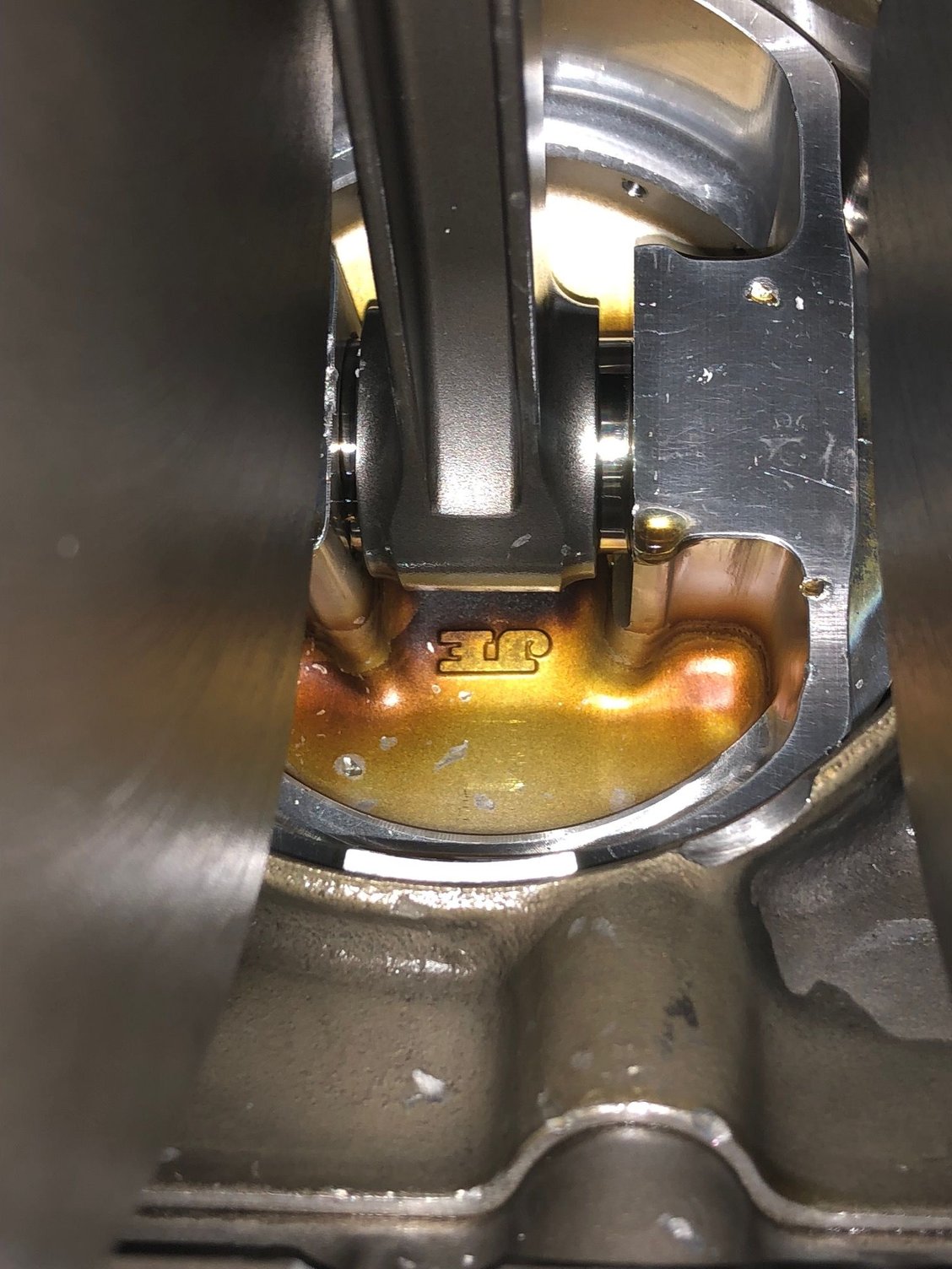
WOOHA Greg, are you kidding? truly, you have to be...... the picture clearly shows MUCH more than 65 thou of offset. your little ".25mm" is only 6 thou............... (CORRECTED not 6 thou, it should be 10 thou, or 0.010) . So, where is the rest of the position change coming from. I think everyone but YOU can see this. its not angle. ive simulated this with a rod and a piston on a bench to show that the rod is NOT centered. why?? it's not an optical illusion. can you take a picture of the other rods and pistons to see if this is true for the rest of them?
Now, if the damage caused the offset to change, that would explain it. but claiming its "perspective" is a little crazy considering it is in plain view that the rod is NOT centered and off by more than the 65 thou (0.065") shown in the static Corrillo diagram which shows increased side forces...... the view is almost directly down the rod to the piston . not enough to "hide" any of the adjacent offset gap. i cant believe you would even mention the 1/4mm space needed at the big ends as a possible cause. the gap shown, is an order of magnitude greater than that spec at the crank. By the way, this kind of engineering analysis WAS my day job for many years.
Originally Posted by GregBBRD
Don't quit your day job....
I think everyone, except you, realizes that the picture was taken from the right side of that rod, which hides the actual gap on the left side.
There's also side to side play in the rods down on the crankshaft (over .25mm), to keep the rods from friction welding themselves together. Unless the rods are perfectly centered on the crankshaft, when the picture is taken, the right to left dimension at the piston can be off by thst amount.
You can relax, concentrate on something else, and quit wasting everyone's time.
These rods are made for 928 cylinder offset and are correctly centered on the pistons.
Last edited by mark kibort; 06-15-2018 at 01:09 PM.
WOOHA Greg, are you kidding? truly, you have to be...... the picture clearly shows MUCH more than 65 thou of offset. your little ".25mm" is only 6 thou................ So, where is the rest of the position change coming from. I think everyone but YOU can see this. its not angle. ive simulated this with a rod and a piston on a bench to show that the rod is NOT centered. why?? it's not an optical illusion. can you take a picture of the other rods and pistons to see if this is true for the rest of them?
Now, if the damage caused the offset to change, that would explain it. but claiming its "perspective" is a little crazy considering it is in plain view that the rod is NOT centered and off by more than the 65 thou (0.065") shown in the static Corrillo diagram which shows increased side forces...... the view is almost directly down the rod to the piston . not enough to "hide" any of the adjacent offset gap. i cant believe you would even mention the 1/4mm space needed at the big ends as a possible cause. the gap shown, is an order of magnitude greater than that spec at the crank. By the way, this kind of engineering analysis WAS my day job for many years.
Mark:
"Over .25mm" is over .25mm!
And .25mm is .010", not .006".
Over is a key part of the wording....I've got zero reason to teach people how to build engines and give out my specifications.....so I'm not going to tell you how much rod clearance is built into these engine.....it's over .010.
And if you were to "shuffle" that rod in the picture .010", and correct the perspective, you'd find it perfectly centered.
When we started over with a clean sheet of paper, building a correct 928 rod, all of this was checked, rechecked, checked again. Then the first set of rods were built and we mocked them up in an engine to make sure they were perfect.
You can relax and quit trying to throw me under the bus.....the rods have the correct offset for a 928 engine.
On the other hand, "Chevy" rods are, indeed, off centerline by .065" and are a disaster waiting to happen, because of the side loading on the connecting rod and the piston being twisted in the bore....each time the engine fires.
"Over .25mm" is over .25mm!
And .25mm is .010", not .006". Over is a key part of the wording....I've got zero reason to teach people how to build engines and give out my specifications.....so I'm not going to tell you how much rod clearance is built into these engine.....it's over .010.
And if you were to "shuffle" that rod in the picture .010", and correct the perspective, you'd find it perfectly centered.
When we started over with a clean sheet of paper, building a correct 928 rod, all of this was checked, rechecked, checked again. Then the first set of rods were built and we mocked them up in an engine to make sure they were perfect.
You can relax and quit trying to throw me under the bus.....the rods have the correct offset for a 928 engine.
On the other hand, "Chevy" rods are, indeed, off centerline by .065" and are a disaster waiting to happen, because of the side loading on the connecting rod and the piston being twisted in the bore....each time the engine fires.
yes, Greg, ".25 mm " is .0098" (sorry mis-wrote it) the point is, even if it is over "1/4mm" its an order of magnitude greater than the distance that the offset is showing. You can move it all you want, and if the movement is near .065" then that's the gap down at the big end and i dont think, you , or anyone thinks that's the case. regardless , if the rod offset can get to this 65 thou , then the forces are explained by the graph. so your secret sauce of MORE than .010 gap might be the issue then, no? you just injected another variable. here is some proof.. if rod offset ON the piston is more than .065", then these are the forces you can expect.
by the way, the ford guys have been using the incorrect offset like this for many many years by using chevy rod offsets.... most have not had any issues. Lots of other factors, but just saying... if you know engines, you would know this. now, is it a problem with our motors using aluminum or open deck cylinders, rod ratios, etc....???? i dont know.. the fact remains, the only variable of the two blown motors is the change of the crank and rods. i visibly see an offset problem and you are denying it is there. show me the other rods in the pistons, and show us the spark plugs too. sure it could have been a lot of things.
by the way, curious, in reference to what Erik said, why are turbo'ed motors easier on rod bearings?
I'll go back to ignoring you for a couple of weeks, or until you post something else idiotic. When the engine comes apart, I'll take a picture of the rods centered on the pistons....looking down the center of the rod. In the meantime, you can relax....they are perfect.
A review, for you...what a bore.
Both the engines that Mark blew up were ultra high compression race engines that he insisted on running street gas through. (Economy move? Let me assure you, one can buy a whole sh!tpot of race fuel for the price of one of these engines. Why the F--k would anyone do this???? What is the savings???? Maybe $500 a day?
You think, for a New York second, that if one of those 911 Cup Car engines running out there had someone running street gas in it (and blew up....which it would do), you'd be having this conversation with Porsche Motorsports?
And these 928 engines had more static compression than any Porsche Motorsports Engine....ever!
Great idea. 75% street fuel. 25% race fuel.
That's like going to the track trying to blow up an engine.
Greg,
I hope you can read this. i took some time to take some pics.... anyway, you could be right about the street gas, but im positive that mark did 50 /50 110octane and 91. isn't that ok?? But, if it detonated, it certainly could have damaged the piston to stop it in the "Bore". (speaking of bore) anyway, my engine is 11:1 also, but have never used anything but 91 street fuel. however, with 20% less HP, that might be the difference in risk. i get that.
so, lets talk observations. i took a piston and a rod and put them together and measured :
1. centered
2. 0,010" off center (0.25mm)
2. 0.020" off center (twice the value you mentioned as being needed at the big end for room to move)
4 . 0.060" close to the value of offset where bad things can happen
Now, you cant see what your "0.010"" might change to the offset. you cant even see twice that. and yet when you see .060" it is extremely noticeable.
now, go look at the piston in the failed engine. you think that is an optical illusion?? think again. not saying that is the problem, but doesn't that make you curious as to how that can be that off center?
of an issue? is it the only one? was it caused by the failure?? again, that picture is with the broken rod end still attached in the crank journal.
Last edited by mark kibort; 06-15-2018 at 01:17 AM.
Take a break from beating an obviously dead horse to death. When the heads come off, I'm sure that Greg will start a thread focused on the actual failure, and cease contaminating your discussion about "any 928's running?" at the Festival of Speed.
No, my name is Erik.
Todd isn't following this saga at all. He's aware of it and if he has anything to say about it, he know how to post.
I'm more involved with Chevy stuff than he is, I've been wrenching on Corvette's since before I owned a Porsche. My comment / question comes from chatting with those guys who scratch their head and ask why "we" are using the bearings not even considered ideal for their highest end builds. They instead opt for smaller / wider "honda" bearings.
Moot point in this thread since the bearings didn't fail, just the odd things I ponder.
And if you were to "shuffle" that rod in the picture .010", and correct the perspective, you'd find it perfectly centered.
When we started over with a clean sheet of paper, building a correct 928 rod, all of this was checked, rechecked, checked again. Then the first set of rods were built and we mocked them up in an engine to make sure they were perfect.
You can relax and quit trying to throw me under the bus.....the rods have the correct offset for a 928 engine.
On the other hand, "Chevy" rods are, indeed, off centerline by .065" and are a disaster waiting to happen, because of the side loading on the connecting rod and the piston being twisted in the bore....each time the engine fires.
Greg, you are too smart to make that kind of statement. the offset of the picture, regardless of the very slight picture angle off center , WILL NOT CENTER ITSELF, when moving 0.010" , nor will it center itself at twice that .........we are talking about 0.060" . you may have sized the rods perfectly, but there are other factors as you also changed the crank on this build.
From the pictures ive posted. i showed a centered rod, i moved it in succession, 0.010, then 0.020 and then to the final position of 0.060" off center. you can see how this almost perfectly looks like the rod /piston position in Joes failed engine. Now, if the failure caused this, it willl be isolated to this one journal , piston and rod. it will be interesting to see the others. but make no mistake... your tolerance of fit, of "over 0.010", doesnt move the rod to the center oft the pin..........there is NO chance of that happening for even double that value (i.e. 0.020" or 0.5mm).
so , if this rod is indeed in the position as it appears, it would be a disaster waiting to happen... (your words). so, tell us how it can be sitting in this position because CLEARY, moving it 0.010" is not going to center it.
For the record I have never said or even thought that Greg did anything improper in assembling this motor. After more than 15 years of racing with a stroker 928 engine (built by Greg) I was simply doing what I have always done with great results. It was brought to my attention that Joseph's motor was not identical to mine as I had thought and it did require a higher octane than I had always used. I guess Joseph and I did not cover during our transaction.
For the record I have never said or even thought that Greg did anything improper in assembling this motor. After more than 15 years of racing with a stroker 928 engine (built by Greg) I was simply doing what I have always done with great results. It was brought to my attention that Joseph's motor was not identical to mine as I had thought and it did require a higher octane than I had always used. I guess Joseph and I did not cover during our transaction.
and i have not said Greg didnt assemble the engine properly, i just pointed out a piston, in a bore that has an offset that from all charts could be a problem. both your engine and joes engine blew up after only a few hours of racing. the only common denominator is that they both had new cranks and rods. an obvious observation is the offset and greg himself said that much is a time bomb.. however, he defended this by saying , his tolerance at the crank would move the piston to the center.. where i showed by example, ,01 or ,02" doesn't make a visible "dent" in that position. its near .060" off center. are all the pistons that way. does that plug really look that bad? what could cause this offset? greg said it cant be the rods being made wrong. could it be the crank? or maybe the implosion itself shifted things. I dont know.. it just seemed like something we would want to look at.
AND, why would Joes motor require such high octane when ive been running "monkey" **** 91 octane for 8 years.. sure, im down 100hp to both the Fan/Anderson engines, but still, there are stock 911Gt3s with 3.8 Liter making 400hp at 12.5:1 compression that still run pump gas 91.... in fact , that is over 100/liter hp, ..........if our motors made over 100hp/liter, they would be making over 650hp. Ive shown that plug to a bunch of mechanics.. many are not convinced its detonation. we shall soon see. i could be way off here. eventually, when Greg shows the piston damage and the other pistons offsets not being as far off, i guess we will know.
The GT3's running that kind of compression were designed for it an account for that in material selection, cam profiles, way more advanced knock detection among other things like DIRECT INJECTION.
Hell, Mazda runs 14:1 compression with 87 octane in their standard Miatas.
We are pushing these engines beyond their designed factory outputs and limitations. You saw the plugs with little ***** of melted metal on them in this thread.
The engines were running too hot, in this case, too low of an octane for the compression ratio as the AFRs were fine. The engines knocked enough to crack a rod and cause a catastrophic failure. This was from not running the correct octane fuel.
This isn't about rod design at this point as any rod would have failed in those conditions. It's about running an engine outside of its intended operating conditions.
and i have not said Greg didnt assemble the engine properly, i just pointed out a piston, in a bore that has an offset that from all charts could be a problem. both your engine and joes engine blew up after only a few hours of racing. the only common denominator is that they both had new cranks and rods. an obvious observation is the offset and greg himself said that much is a time bomb.. however, he defended this by saying , his tolerance at the crank would move the piston to the center.. where i showed by example, ,01 or ,02" doesn't make a visible "dent" in that position. its near .060" off center. are all the pistons that way. does that plug really look that bad? what could cause this offset? greg said it cant be the rods being made wrong. could it be the crank? or maybe the implosion itself shifted things. I dont know.. it just seemed like something we would want to look at.
AND, why would Joes motor require such high octane when ive been running "monkey" **** 91 octane for 8 years.. sure, im down 100hp to both the Fan/Anderson engines, but still, there are stock 911Gt3s with 3.8 Liter making 400hp at 12.5:1 compression that still run pump gas 91.... in fact , that is over 100/liter hp, ..........if our motors made over 100hp/liter, they would be making over 650hp. Ive shown that plug to a bunch of mechanics.. many are not convinced its detonation. we shall soon see. i could be way off here. eventually, when Greg shows the piston damage and the other pistons offsets not being as far off, i guess we will know.
Mark:
Like I said, ignore until you say something completely stupid, again.
From the above statement, I know you have no idea how much .060" looks like, in your head.
.060" is the thickness of an American quarter!
When the rod is off .060", the "short" side dimension will actually be touching the piston pin boss!!!!!
Every single engine that I built for Mark Anderson, before his last engine, used "Chevy offset" connecting rods....supplied by Mark Anderson. On every single previous engine, I had to machine the inside of the piston boss, on the "short side", so the connecting rod did not rub on the piston boss!
The picture you keep referring to, isn't anywhere near .060" off! It simply off from the perspective of where the picture was taken from.
Some interesting parts in this thread, and some other not so interesting parts.
The A-beam rod is stronger under compression than the H-beam rod design, for given weight. That's why almost all factory rods are of the A-beam design. The H-beam design is cheaper to manufacture in small series, that's why aftermarket rods are often of the H-beam design. Normally aspirated engines usually fail under tension, though, and the A-beam and H-beam are about equally strong under tension. Just the rod cross-sectional area matters for tension, not so much whether the beam is A or H design.
The weight of the piston assembly and stroke are probably the main factors determining what kind of rod one needs. I think that the right rod for 400g piston assembly is different from the right rod for 700g piston assembly.
I don't think it's the maximum piston speed per se that determines the safe redline for the engine from the rod perspective. It's the load on the road under tension, and that is directly influenced by piston assembly weight.
Then there's the question about rod bearings. A car factory goes thru a lot of computer time and physical testing to produce a rod-bearing-journal system that works well with bimetal aluminum-steel bearings. They like those bimetal bearings because they last forever in various adverse conditions as long as they don’t see too much load. Porsche 928 has bimetal aluminum-steel bearings, including Glyco bearings. The rods are made just strong enough to not deform more than they safely can under those loads. The bearing clearances are small and oil thin to save fuel in newer cars. It all works great, since it's designed to work together as a system.
Now, suppose we hotrod the engine by increasing rpm, the easiest way to make N/A power. The increased rpm now deforms the stock rod big end more. The stock bearing sticks from the sides, and then burns and spins. To cure that, one needs a larger bearing clearance (and eccentricity) and thicker oil. The larger bearing clearance (holding the journal diameter constant) now creates a much larger pressure gradient in the bearing surface — that’s just a consequence of the geometry. The ability of the bearing to carry load goes down due to larger clearance, while the load has increased because of the higher rpms. Consequently, the bimetal aluminum-steel bearing now “wipes out” in that the material shifts in the top layer until deformation and failure.
At this point, the choice is to either design and install a stronger rod and/or lighter piston that deforms less at the new redline rpm and move back to smaller bearing clearances for the bimetal aluminum-steel bearings. This is the car factory solution.
Or, alternatively, sticking with the existing rods and larger bearing clearances while switching to bearings that have a much harder surface layer that can hold the higher load caused by the larger clearances (and higher rpms) without wiping out. I think this is what Clevite racing bearings are like. This is the hot rodder solution.
I don't think that knock is a major contributor to rod failures in normally aspirated engines. Different story for high power density turbocharged engine. For normally aspirated engines, I am guessing that rod failures are due to mostly high rpms and heavy pistons -- or something else failing first, such as rod bearing oiling. I'm sure that aftemarket rod manufacturer will attribute most failures to "user error" of some sort, but they are conflicted.
In terms of engine management, I think both the efforts to extend the stock computers and creating fully developed aftermarket ECU solutions are worthwhile.
It is not true that knock can't be detected above 5000 rpm. Only cheap and/or poorly engineered solutions have that sort of a limitation. The 928 S4 and later, for example, don't shut off knock detection at high rpms and by my experience do a good job detecting knock at 6000 rpm, for example. The knock detection window in an eight cylinder engine at 8000 rpm is something like 400 microseconds and new computers can handle a large number of instruction cycles over that time. I think the modern systems even in not so expensive cars vary the reference spectrum and knock frequency by rpm, I think even the ancient, analog SAAB APC from the 1980's varied the reference level and frequency window by rpm.


 06-14-2018, 01:48 PM