When you click on links to various merchants on this site and make a purchase, this can result in this site earning a commission. Affiliate programs and affiliations include, but are not limited to, the eBay Partner Network.
Well, really, how to replace the DME relay with a couple normal relays. I just typed this up in a PM so I thought I may as well post it up since I did all the typing already. This is a pretty straightforward mod that will work even on a stock 944. I did it for my standalone setup but I can see it being nice for people who just don't want to deal with the DME relay problems (or DME relay location...early car owners....) Just posting it for posterity, most people don't have problems with DME relays but who knows.
Don't proceed unless you have a good understanding of relays and how to solder or at least crimp.
In short, you need 2 generic relays and a fuse block.
That fuse panel has a main lug, which makes it easy. Plus you have a couple auxiliary fused power terminals if you want to power other things, like wideband, etc. You can use whatever relays you want, but these are cheap and have the connector included with wiring you can solder or crimp your connections onto.
This would be easiest if you made an adapter from the DME relay socket, which you can make using a hacked up DME relay. DIY spirit required here.
This setup uses 2 relays, one is a main relay and one is just for the fuel pump. The overall structure is that the ignition switch activates the main relay. That relay allows +12v to power the main lug on the fuse panel. From there, you pass +12v to one of the activation pins on the 2nd relay. The other activation pin is grounded by the DME when it sees RPM. That opens the 2nd relay, which is for the fuel pump. It takes +12v from the fuse panel and then that goes into the harness.
I'll post the wiring info, you'll need to find a place to mount everything (I did mine off the back of the passenger kick panel). For doing it into the stock DME relay socket, here's what you would need to do (Socket XX refers to the pin female terminal in the factory fuse block):
Socket 86 --> pin 86 on new relay #1.
Socket 85 --> pin 85 on new relay #1.
Socket 30 --> pin 30 on new relay #1.
Socket 85b --> pin 85 on new relay #2.
Socket 87 --> connect to one of the fuse panel terminals.
Socket 87b --> pin 87 on new relay #2.
Then you have to connect the relays to the fuse panel.
pin 87 on new relay #1 --> main (shared) lug on fuse panel
pin 86 on new relay #2 --> connect to one of the fuse panel terminals. 5 amp fuse
pin 30 on new relay #2 -->connect to one of the fuse panel terminals. 20 amp fuse
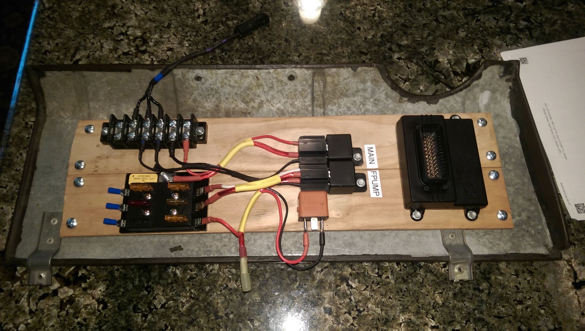
Here's a photo of my panel, back when it was only doing the DME relay duties. I've since used all 6 of the fuse panel slots and added relays for my coils and cooling fans. I recommend a labeller, I paid $15 for mine at Office depot on sale. In the photo, ignore the orange relay. that was there for testing something. I also didn't use the DME relay socket, so this doesn't show how it was connected to the car (that terminal bar at the top left can also be ignored, it was for interfacing with Megasquirt).
That's definitely a valid point! I just got really salty about the DME relay after it had cost me a tow the day I bought the car, has left me stranded on a date, and is in a terrible location on the early cars. I think my bone structure has genetically morphed from having to access that panel so many times.
I forgot to add to the post... here's a cool extension you can do with this, add 'status' LEDs. Just put a simple LED inline with the 1k ohm resistor (long lead of a generic LED) and connect it to pin 87 on each of the new relays. Ground the other side of each LED (short lead...you can ground to pin 85 on the new main relay or wherever convenient). Each LED will light up when that relay is active.
You can mount them local to the relays, or remotely for viewing from a seated position. Less guessing when there's a no-start.
Another think I forgot to add is that you may want to mount your assembly on something with a little shock absorption. You can't tell in the pic I posted, but I actually cut up a bicycle inner tube and sandwiched it between the kick panel and the wood base. That's just because the main failure mode of the DME relay was to crack solder joints due to vibration. While these are an inherently more reliable design (less physical mass mounted inside each relay) it can still be a smart move.
Part of the problem with the DME Relay is that all the weight of the parts is hanging on the electrical contacts and vibrating and cracking...
These relays have their weight held down by the screw/body of the relay, and are a lot cheaper to replace (and easier to find) if necessary.
Michael, I was thinking about this last night though, and I don't see the necessity of the fuse panel in this setup though. All it serves to do is act as an easy distribution block for power from the relay #1 into relay #2...but you could just connect the wires together and achieve the same thing.
Since the original DME socket is still part of the equation the existing fuel pump fuse is still used. Although I guess its not a bad idea to fuse the DME itself.
I dont know where the location is for the early cars. I assume it's like the 924, under the dash. and i can see why you would have done that.
I would have done something else. I would have actually relocated the relay/s (depending what you do) to under the bonnet. would have put them in a box. You can buy relay and fuse boxes for that sort of stuff.
Re: no fuse panel. That's true, I had the same thought. Having the fused power takeoffs is nice but definitely not necessary for a stock 944. I have all my relays, coils, ECU, wideband, idle valve, crank pickup, and fuel injectors fused and powered off it (10 AWG to the battery, wouldn't want to power all that from a tap into the stock relay panel).
For not using the fuse panel, you would do the following scheme:
Socket 86 --> pin 86 on new relay #1.
Socket 85 --> pin 85 on new relay #1.
Socket 30 --> pin 30 on new relay #1.
Socket 87 --> pin 87 on new relay #1.
pin 87 on new relay #1 also connects to:
pin 86 on new relay #2
pin 30 on new relay #2
Socket 85b --> pin 85 on new relay #2.
Socket 87b --> pin 87 on new relay #2.
Would make for a more compact setup, you could just stick the relays somewhere.
-----
Ok, another thing I forgot to add... the relay sockets (from the Amazon link in OP) have 16 or 18 AWG wire, I forget. It's smart to replace that with thicker wire for connecting pins 30 & 87 of the new relays. They'll see the most current since these power the fuel pump and the DME, and remember the DME sinks high-power grounds for the injectors and the coil.
You can use a nail or something to get the female terminal out of the socket (there's a tang you have to depress on the female terminal), and use a small flathead to un-crimp it from the thin wire. Then gently use needlenose pliers to open up the crimp tabs and form it around the new thicker wire. You can use a crimp tool to complete. I soldered on top of that (just enough to 'silver' the union) and used heatshrink. Be careful not to damage the tang that keeps the terminal inside the plastic socket, it needs to stick out slightly to catch. If your terminal won't stay back in, that's probably why.
Yea, but you could build this new relay harness 10 times for the cost of the solid-state piece which hasn't really been tested...whereas these are just run of the mill reliable relays wired together.
My 993 (part number) relay was the one that failed within 30 minutes of buying this car (no idea how old it was though). Rookie mistake on me for not having a backup. The issue is with the design like Spencer said, the weight of the relay (which matter, cause you have 2 stages in one relay) is supported only by the pins. Which are held by solder. And it gets shaken around, which fatigues the solder.
I think the solid state relay is cool, when I was doing mine it wasn't available though. And their website said not in stock when I checked yesterday.
If you're going to go this route, and I was myself before the availability of the solid state relay, I would get name brand relays, like NOS (or even used) Bosch, or Hella relays. The usual ones as seen at every auto parts store across the nation aren't much better than Uro stuff..
IMO It'll be a few years before we know for sure if the solid state relay is as good as the updated OEM part (not the Uro cheapo aftermarket). Maybe it is as simple as hot gluing the internal relays to the pcb for added support. Maybe the fuel pump draws a lot of current if the fuel filter is neglected and this is hard on the relay module. I never really looked into it. I always assumed people with persistent DME relay problems actually had DME or pump or wiring or alarm problems.
IMO It'll be a few years before we know for sure if the solid state relay is as good as the updated OEM part (not the Uro cheapo aftermarket). Maybe it is as simple as hot gluing the internal relays to the pcb for added support. Maybe the fuel pump draws a lot of current if the fuel filter is neglected and this is hard on the relay module. I never really looked into it. I always assumed people with persistent DME relay problems actually had DME or pump or wiring or alarm problems.
Maybe it would be a wise step for 944'ers who do this relay mod, to run a new set of wires to the fuel pump - stock wiring is a little small, IMO, which causes resistance and heat at higher current levels. Not to mention the wires are so old they probably have some added internal resistance in them now.
Don't know what size the stock wires are, but it wouldn't hurt to go one-size up.

 01-19-2016, 09:19 PM