When you click on links to various merchants on this site and make a purchase, this can result in this site earning a commission. Affiliate programs and affiliations include, but are not limited to, the eBay Partner Network.
Hmm, sounds like a lot of work. Unless the old wire is wicking moisture and turning green I would doubt it's much of a problem. Easy enough to check the resistance and voltage drop though.
I am often not impressed by the gauge of wire used on P cars though. Maybe there is a modern fuel pump that is more efficient. It'd be easy enough to measure the fuel pump current with a DME relay jumper. I reckon it should be under 10 amps under load. I doubt the fuel pump relay contacts are rated much over that. With an ammeter plugged in as a jumper I suppose you could clamp the fuel return line and see what sort of current you get up to. Briefly. That'd show you the kind of current you might hit if you install a dry nitrous kit off an old five-oh.
I dug out a spare DME relay, 944 part number from 1987 (made in West Germany back when that was a thing!) and it looks darned simple and robust but I see what other people have noted about the copper braid possibly fouling the relay armature and that the upper (DME) relay hanging onto the board by the solder pads. It'd benefit from having the upper relay glued to the board IMO and I might as well do that since I need to glue something else anyway. Kinda tempting to put a dab of hot glue in the top of the case to grab the top relay when the cover is put back on. Hot glue is nice for this sort of thing as it pops apart pretty easily if applied to smooth surfaces.
Re: the thread topic is the diode in the DME relay circuit not needed here as well? I think you've connected what is essentially a little ignition coil to your DME ground and ignition switch, it might arc your ignition switch as pictured.
Re: the thread topic is the diode in the DME relay circuit not needed here as well? I think you've connected what is essentially a little ignition coil to your DME ground and ignition switch, it might arc your ignition switch as pictured.
-Joel.
Could you elaborate on that? I know there's one coil per relay (that draws the relay contacts together) but with separate relays, there isn't a second inductive coil nearby. That might be a problem with the original design, where there are 2 coils in one housing, meaning the diode was needed. I've been running this setup for 6 months with no problems, it just works.
Re: fuel pump wiring. On my 1983 it's ~14 AWG, visually thicker than the other wiring in the loom it is a part of. The internal condition was fine when I spliced into it so I didn't mess with it. The ground point for the pump is probably in worse shape on your average 944 unless it's been cleaned.
I'm sure it'd work, but the coil of wire in the relay stores energy that has to go somewhere when the circuit is switched off. I'm too devilishly handsome to be an electrical engineer but what I believe happens in this case is that you get a big voltage spike arcing across the ignition key switch, if indeed that is what is directly connected to terminal 86.
For the fuel pump relay there may be the same sort of thing, a snubber or flyback protection of some sort in the DME itself. I'd be mildly concerned about this circuit in your case as you are probably putting a lot more energy back into that circuit with this much bigger relay. In the case of the ignition key switch I'd both be worried about arcing in it (because it is a pain to replace) and whatever else it is hooked up to, like the DME which sure as heck would not want to see voltage spikes. Voltage spikes caused by jump-starting are one of the well-known ways to kill a DME (note: not the relay but the DME brain itself, the ECU, the engine computer).
I'd bet a shiny nickel the spike hits your DME, if you still run one, and is more than 100 volts. You'd need a scope to measure it.
Very interesting. I haven't had problems (running a Megasquirt instead of a DME) but I can see how diodes or caps would be good to have there. Another idea would be to simply remotely mount the DME relay, and secure it by the case instead of by the pins.
Yeah I took a spare I had, a 944 part number from 1987, and hot-glued the relay chassis to the board and then hot glued the upper relay to the inside of the case to try this out. I do not really see how the part might fail in this configuration.
If you want to use those fog light relays it'd probably be a good idea to spend the quarter and put a diode in to protect those circuits.
Bumping this up, I am going to build my own little setup as described by odonnell, and incorporate the ignition coil power into it as well. (the black wire from ignition switch to coil, mine is faulty)
Also, I'm going to do a voltage check at the fuel pump and see if it would benefit from its own relay and new power wire, will share details/pictures when done.
This should last long enough for me to lay out a full-car rewire in coming years...
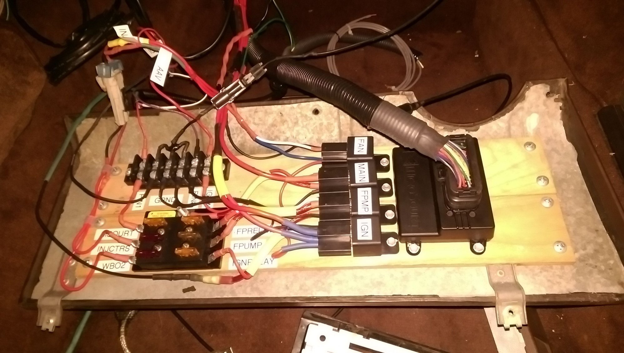
FWIW I noticed my fuel pump is noticeably louder now vs stock setup, maybe less of a voltage drop? I have the power coming from the battery right to the main relay (triggered by ignition switch) via some 10 AWG. From there is goes into the 6-gang fuse block, and fused 20A to the fuel pump relay (triggered by MS when it sees RPM). From there it tees into the green/black fuel pump power wire that runs by the E-brake. My coils are also powered by a relay (triggered by the ignition switch), otherwise it would be up to 16A going through the cheap plastic switch...LS coils in wasted spark.
Snapped a picture of the relay panel last night after pulling the kick panel, present state. Highly recommend the labeler, I would have forgotten what each wire was for almost a year after putting it together.
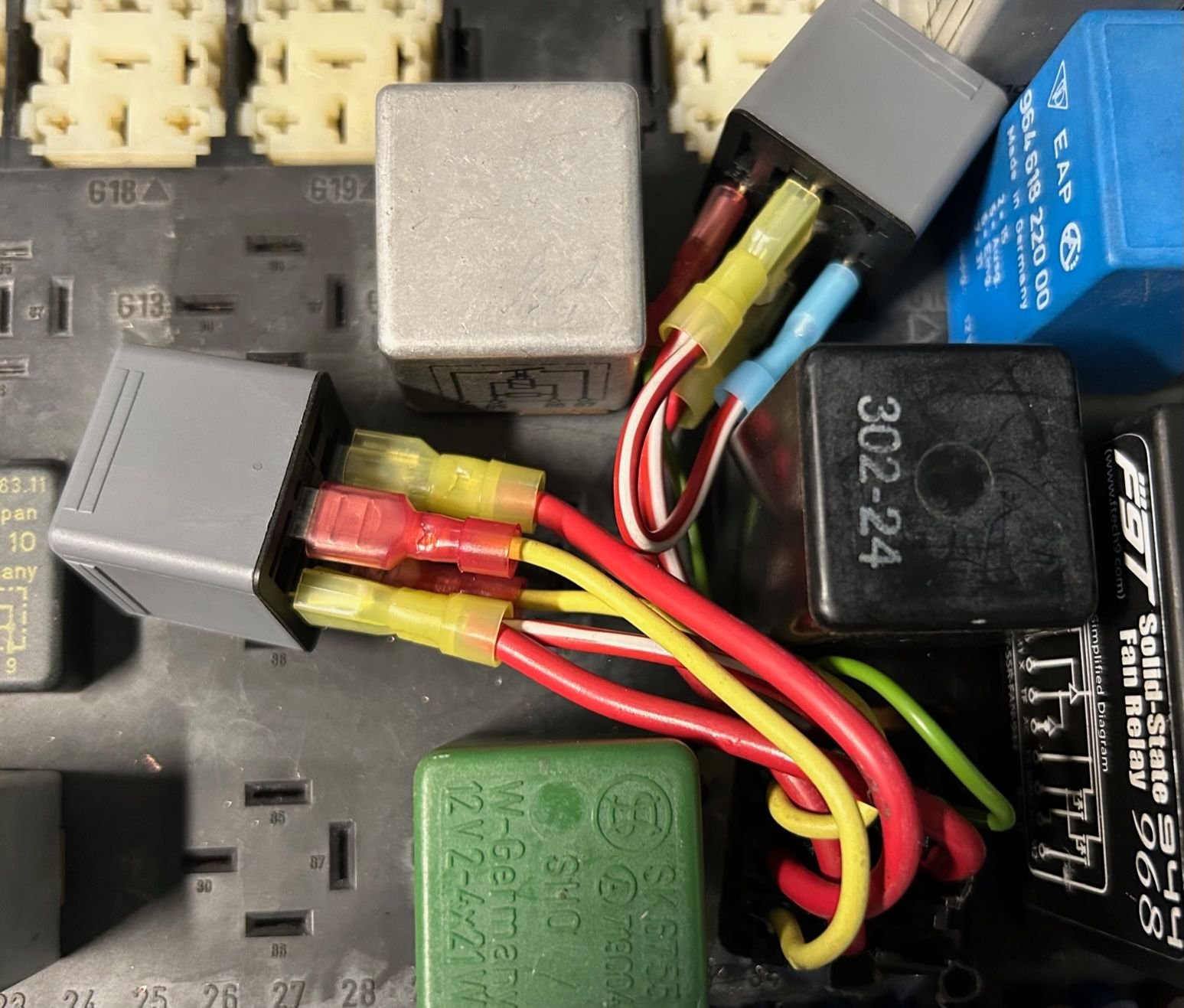
I did a slight modification on this with direct pinout from the late stock relay slot. I cut out the plastic cover above DME relay slot and soldered wires with connectors to the relay terminals on my race car; filling gaps with hot glue to add support to the wires. The pins were bad and would cut power in hard turns or over bumps.
I found the updated instructions a little confusing because you had to double-up on the wire going from relay one pin 87 into relay two at pin 30 and jump a wire from pin 30 to the relay trigger at pin at 87 on relay two. This made the daisy-chain reaction needed for both relays to run concurrently. I'll Velcro the relays down.
Because it's a race car I pulled a lot of the other relays that weren't needed and that gave me space for the rewire. Not sure I'd do this on a street car, hope it help a few racers down the line.
Yes, if your fusebox connectors are bad and you want to make good connections on the little relay pins. I tried the solid state relay but it wouldn't work on my car for some reason. Still not sure why.

 01-22-2016, 10:16 AM