When you click on links to various merchants on this site and make a purchase, this can result in this site earning a commission. Affiliate programs and affiliations include, but are not limited to, the eBay Partner Network.
That's fair. I may be in the minority, but I can wrench all day and tackle mechanical issues no problem but the idea of getting something like MS to work makes my brain hurt. Any system I go with needs to be close to plug and play, and as stated above, if it's paired with the ITB's by the seller all the better.
Not telling you what you have to do, just thinking out loud.
MS is very easy to set up - I am definitely not a computer guy but there is a ton of documentation out there and the basic instructions are pretty clear.
Plus several guys have done MS 944s before so all the specific info is available.
Any 944 owner is doing themselves a big disservice by using the original DME anymore, even on otherwise stock cars.
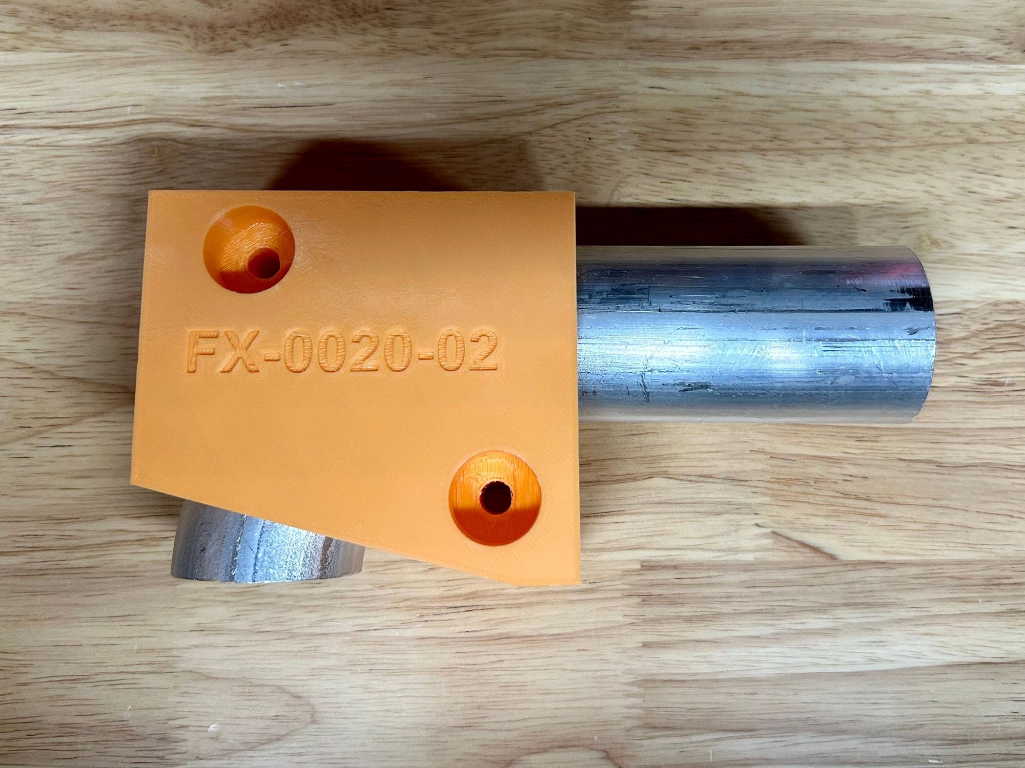
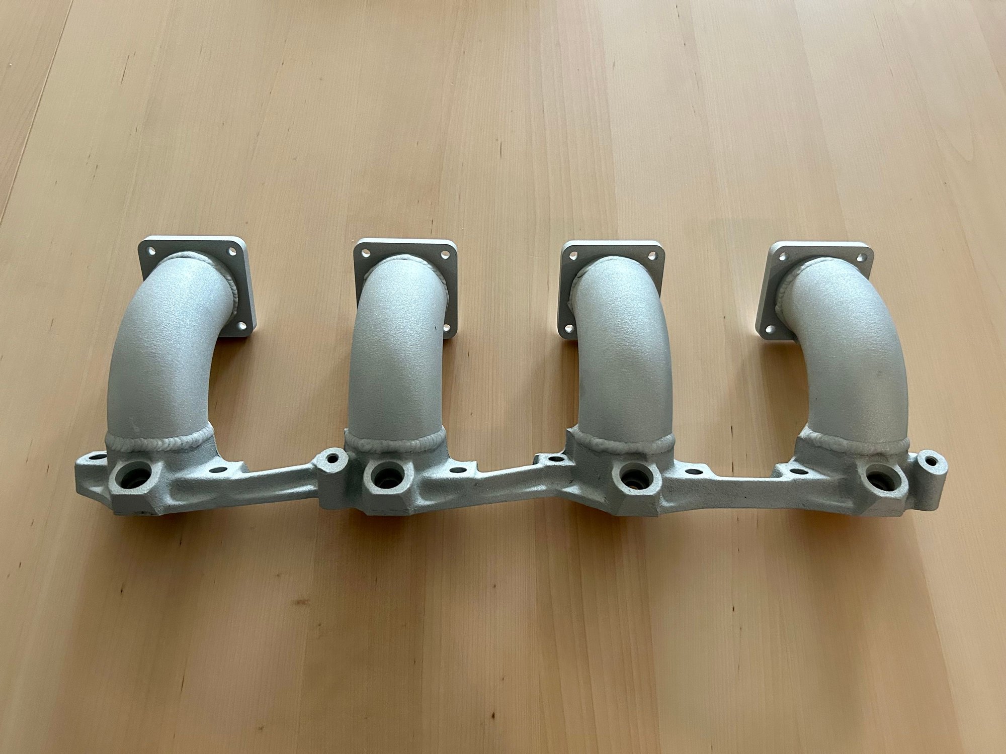
Small update here....I made a 3D-printed fixture to cut down the pipe elbows for the inlet manifold. This way each elbow was cut down to within probably +/- 1 degree and less work than trial and (mostly) error would have achieved. This allows for additional units to be made this way in the future, if I so choose.
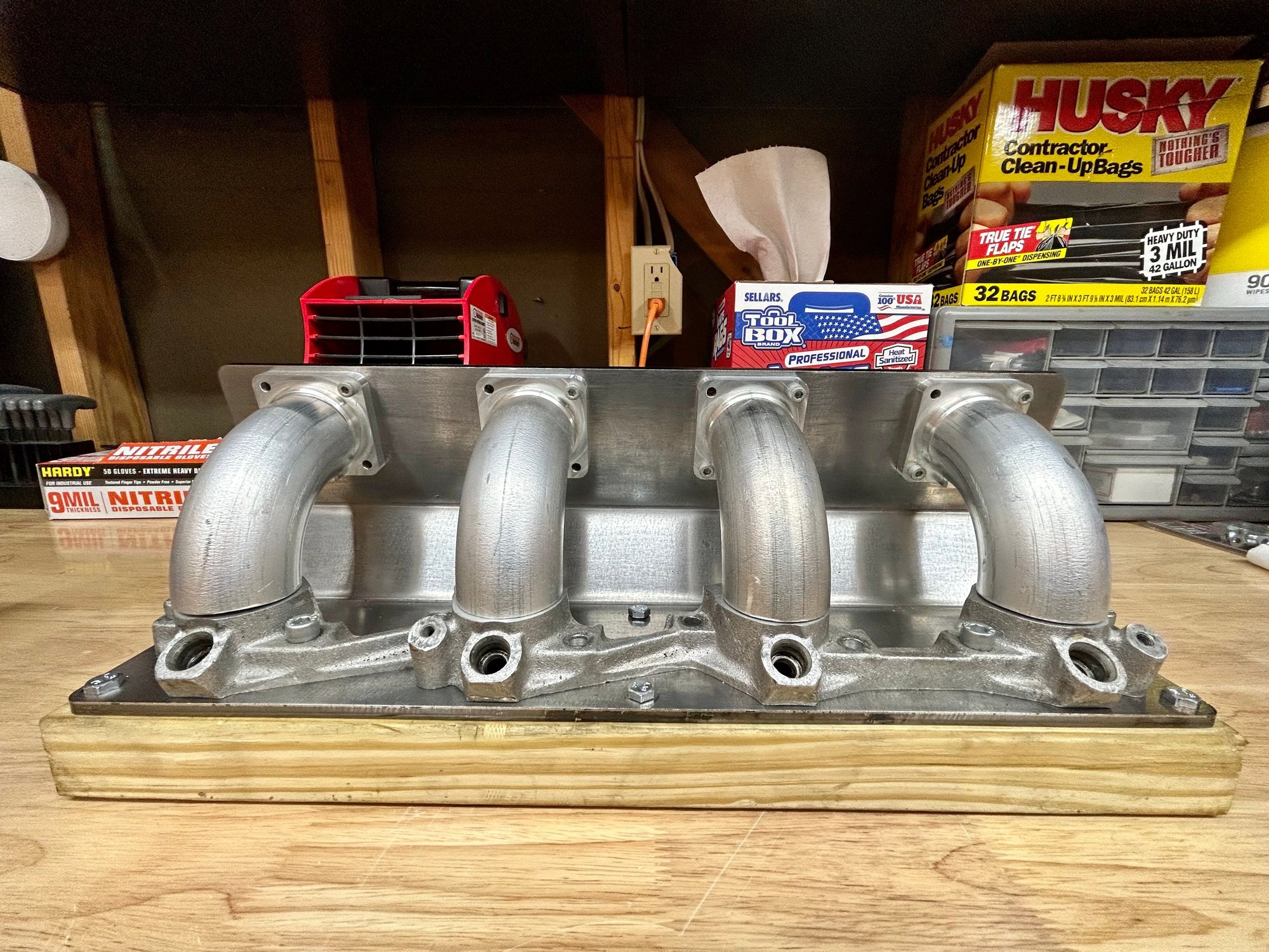
I had a sheet cut steel fixture made for mounting the four ITB flanges and the main base flange. I mounted it to a piece of 2x6 for better support and bolted the flanges to it to hold everything in place for welding.
I plan to take it for welding this week. It should turn out pretty nice I think.
I must�ve read this wrong. You are going to weld steel to aluminum? Please confirm. TIA
Nope, not going to weld steel to aluminum. The steel fixture is just for holding the flanges and elbows in place for welding. The manifold will then be removed from the fixture.
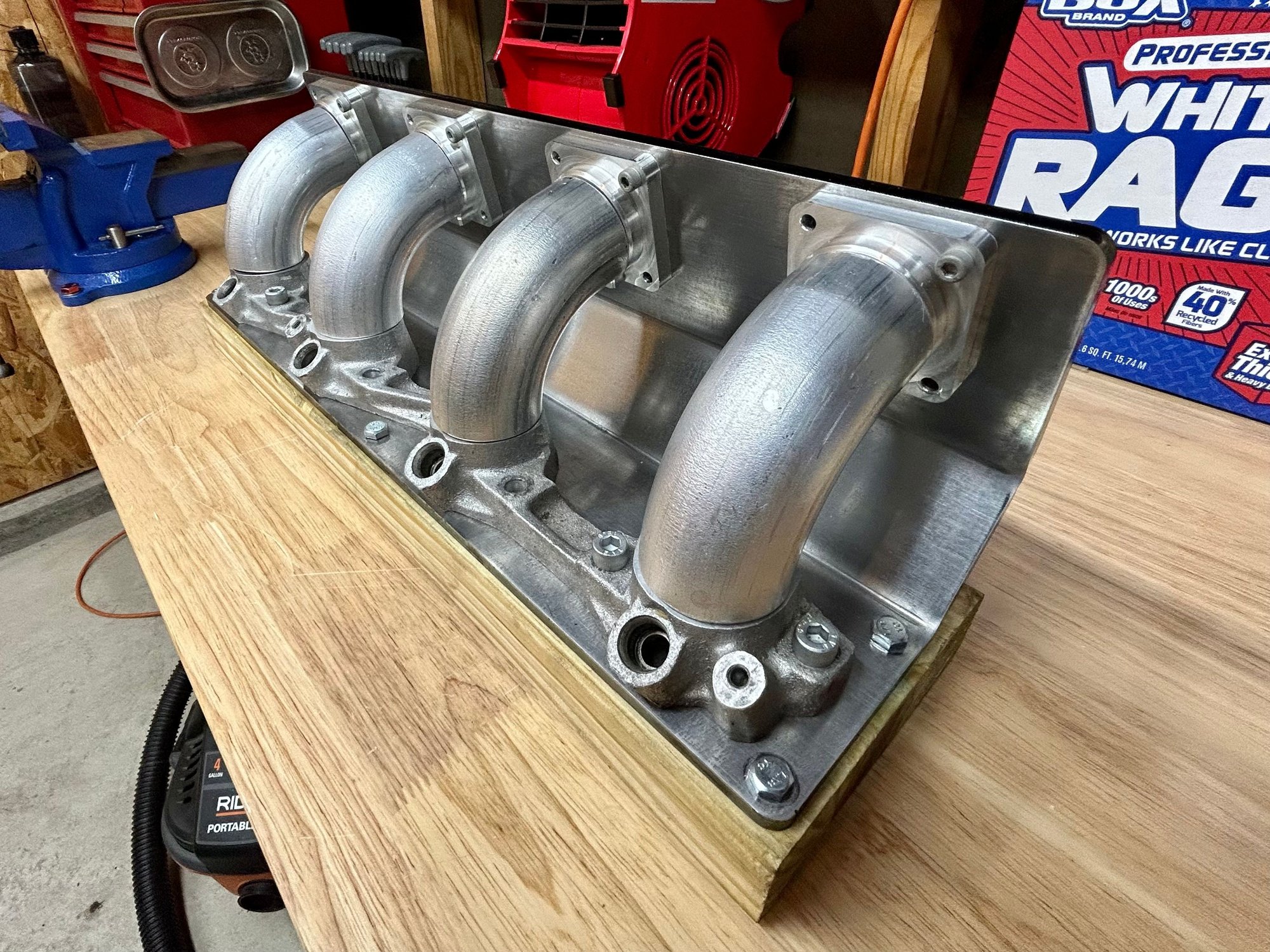
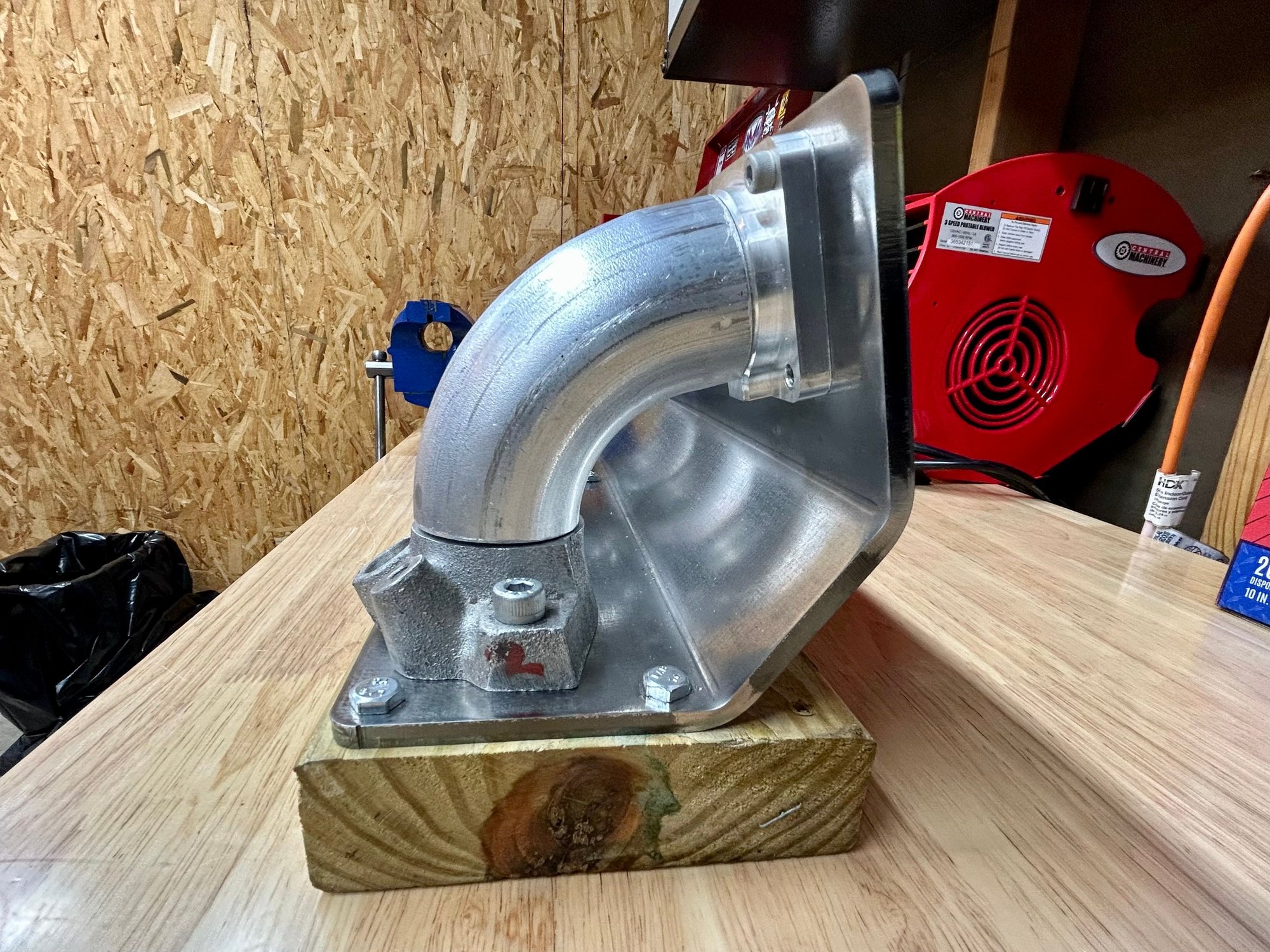
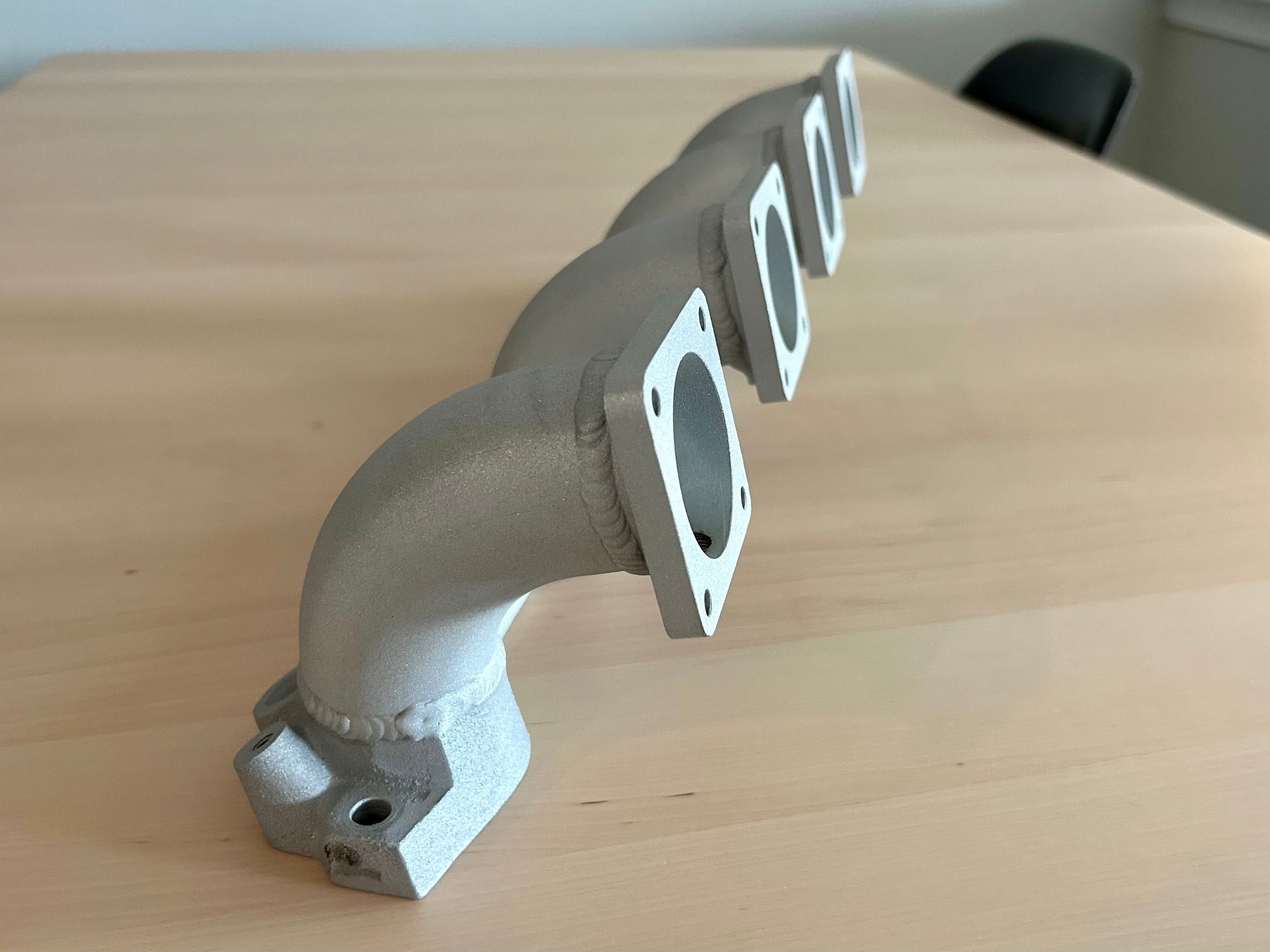
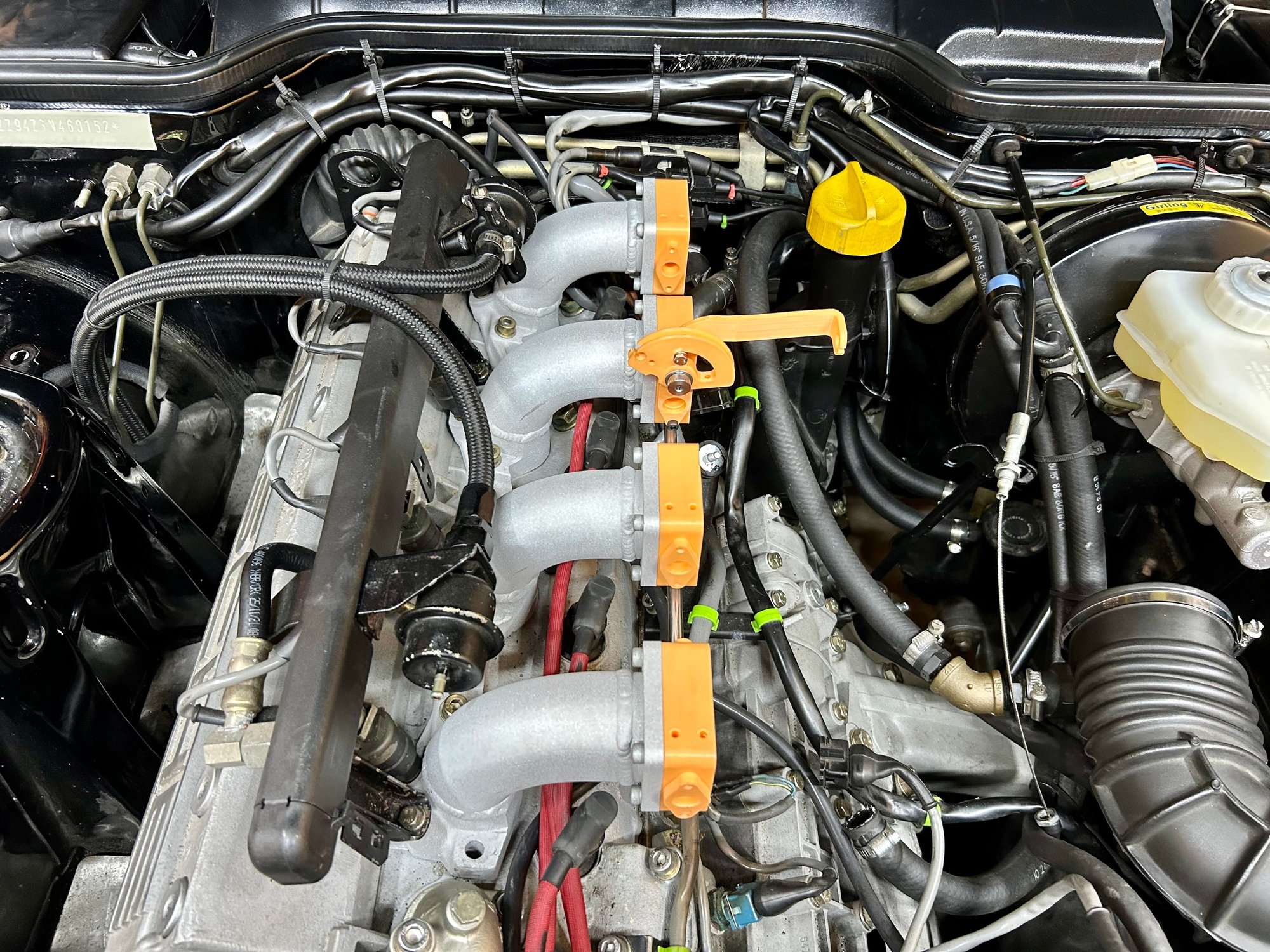
Got the inlet manifold back from welding and blasting so I could test fit my mock 3D-printed throttles. Welding was done by BDF, Inc. in Souderton, PA. I will need to do a little bit of grinding inside to clean up the edges, but overall it turned out really nice.
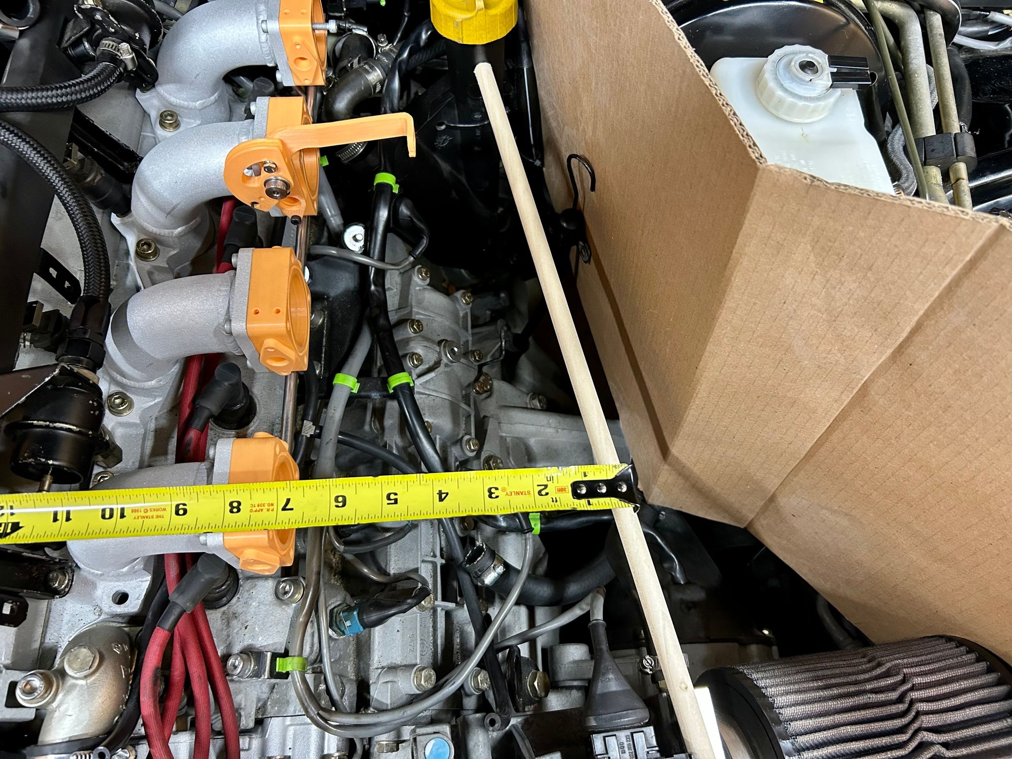
Test fitted on the car to make sure the throttle linkage cleared the hood (it does) and to confirm that there is plenty of space to access the spark plugs with the inlet manifold installed.
The throttle cable bracket was really just a total guess to get a baseline for future revisions. I was more concerned with getting the under-hood clearance right and having a bracket that isn't fixed to the top of the plenum. Looks like I can do a few things:
Move it to the other side of the cylinder #3 throttle (mirroring its current design) and keep the stock NA cable, albeit shortening the cable a bit and installing a cable end.
Keep the throttle cable bracket where it is and increase the depth of the cable bracket to perfectly fit the stock NA cable.
Keep the throttle cable bracket where it is, use a Turbo or S2 cable and adjust the throttle cable bracket only slightly.
Anyone know the difference in length between the NA and Turbo or S2 cables? I suspect the cable sheaths on the Turbo/S2 cables are a bit longer while the actual cable is a bit shorter, but that's just a guess without purchasing them to check for sure.
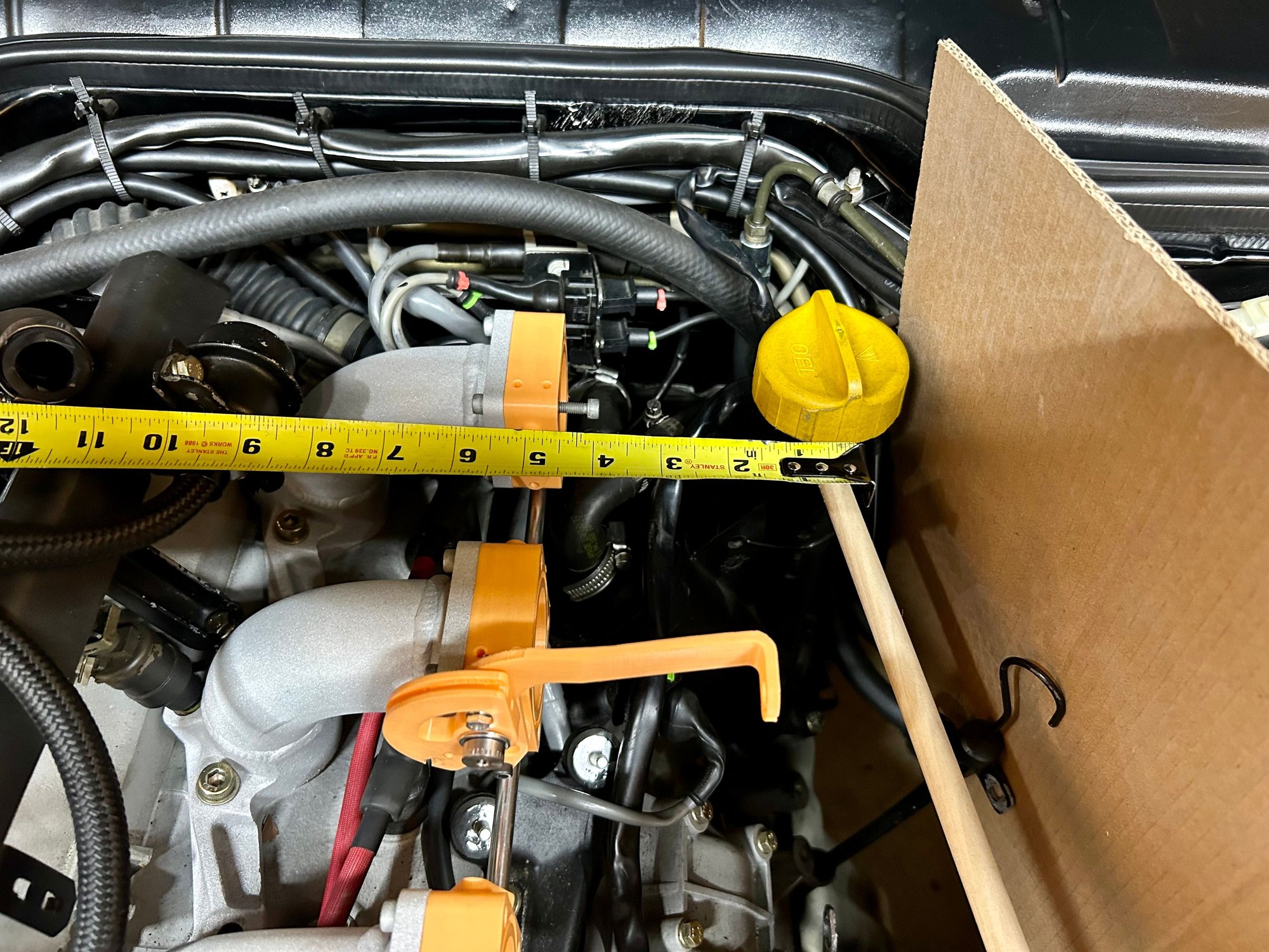
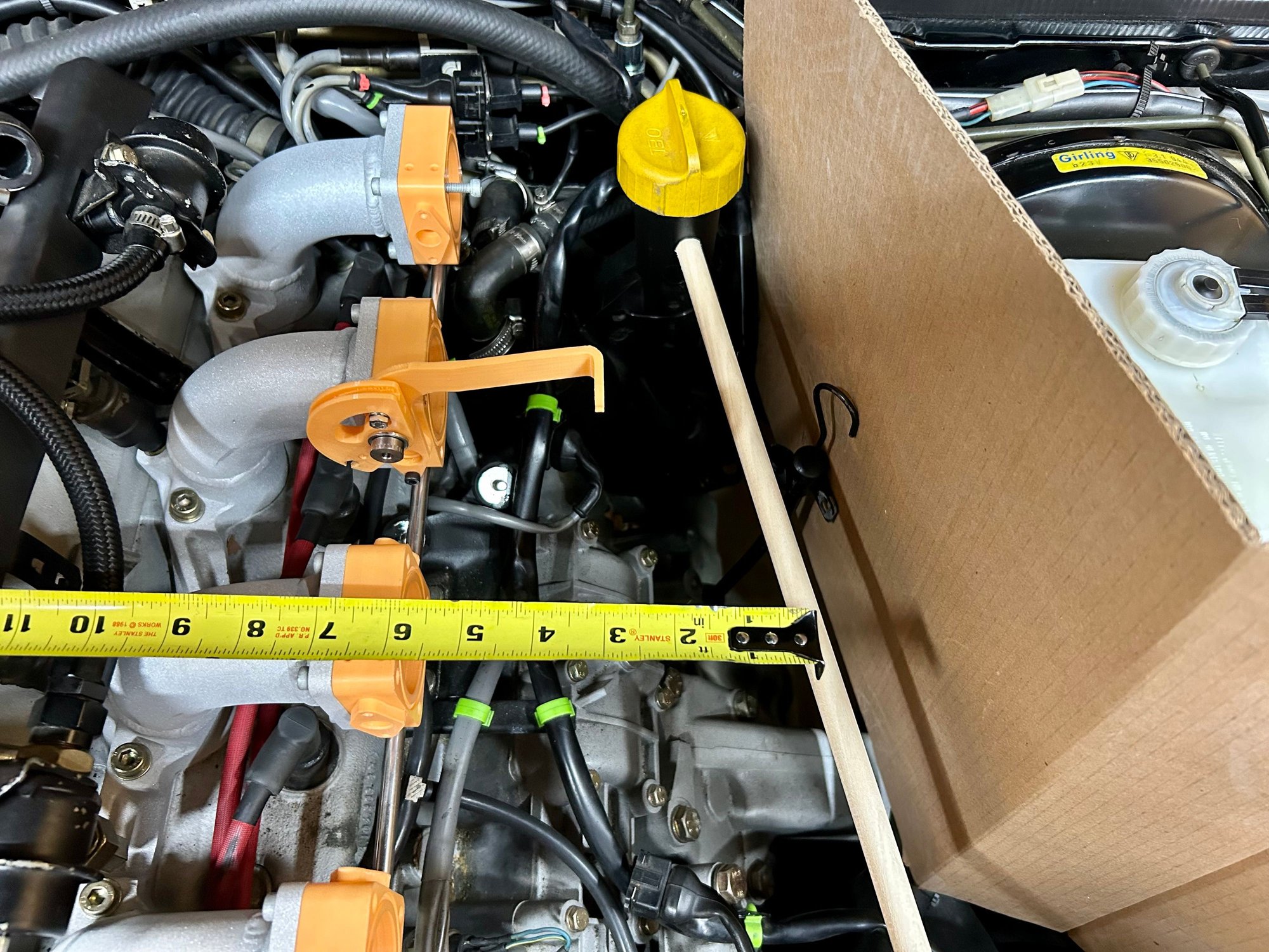
I was originally considering shortening/changing the oil filler for better plenum clearance, but now I'm considering design a plenum around it. I know - cylinder #4 won't have as much free space around it as the other cylinders, but one of my goals with this project is to make it look kind of factory. I think I could develop a decent wedge-shaped plenum that fits around the oil filler and overall the system would still work quite well. Thoughts?
I am designing this with the goal of it also fitting the 951, so I'm simulating the 951 heat shield with the piece of cardboard. It's a rough measurement but should put me in the ball park until I can test fit on an actual 951.
The thermo-valve for the charcoal canister won't fit with these ITBs, which is not an issue for me since I gutted that whole portion of the emissions system. I will also have to slightly relocated the IAC valve since it hits the throttles. Seems easy enough with a simple bracket.
So there we have it. Enjoy the update and have a great week.
I was originally considering shortening/changing the oil filler for better plenum clearance, but now I'm considering design a plenum around it. I know - cylinder #4 won't have as much free space around it as the other cylinders, but one of my goals with this project is to make it look kind of factory. I think I could develop a decent wedge-shaped plenum that fits around the oil filler and overall the system would still work quite well. Thoughts?
JRP
It looks great - I'm so hyped for this.
I'd rather move the oil filler than compromise the plenum design; it shouldn't be hard to cut the filler down and then add an extension to move it a few inches towards the brake booster.
the recipe i put together once upon a time was using an NA AOS cap on a 944S AOS base. it deletes the long oil filler neck entirely but the AOS still works.
you just gotta fill the oil through the valve cover instead.
the recipe i put together once upon a time was using an NA AOS cap on a 944S AOS base. it deletes the long oil filler neck entirely but the AOS still works.
you just gotta fill the oil through the valve cover instead.
That definitely looks clean, but then you can't add any oil without tools. My preference is to continue utilizing a cap of some sort to make adding oil simple and easy.
I'm definitely not opposed to relocating the oil filler, but I couldn't help consider just keeping it in place when I was test fitting and realized I had a decent amount of space with my short throttle body design.
Does ITB. assembly have 2 separate spring returns for safety?
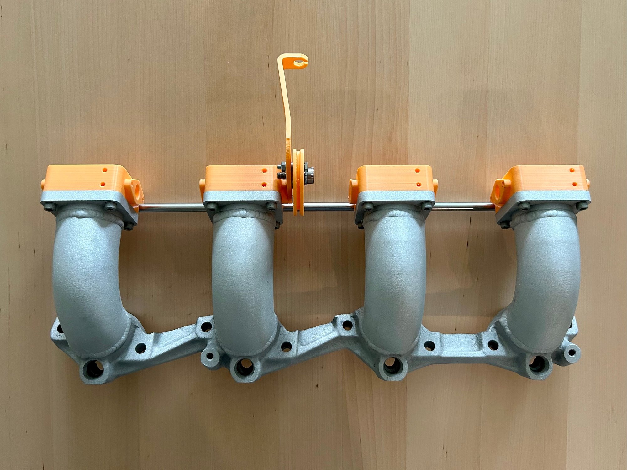
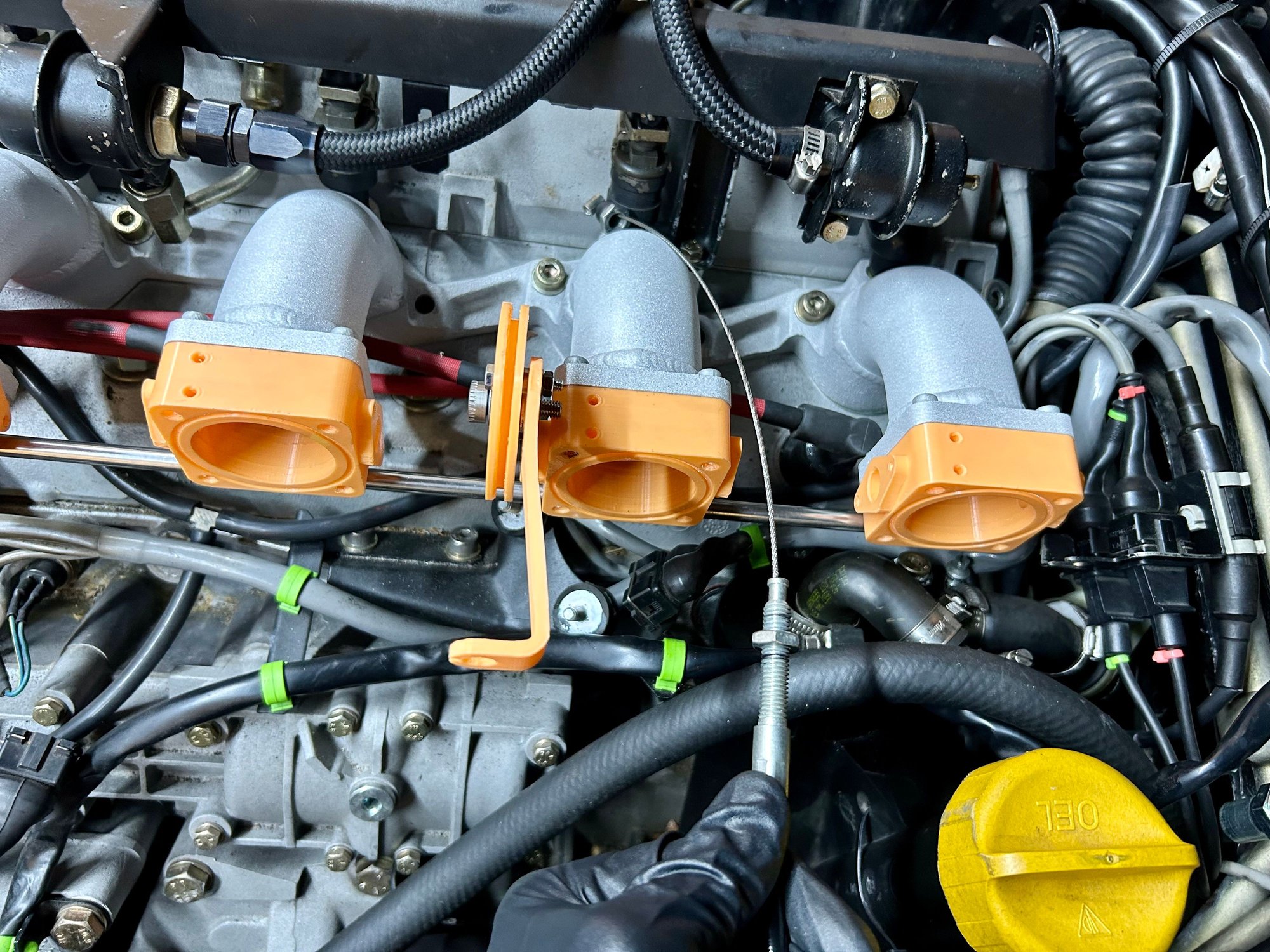
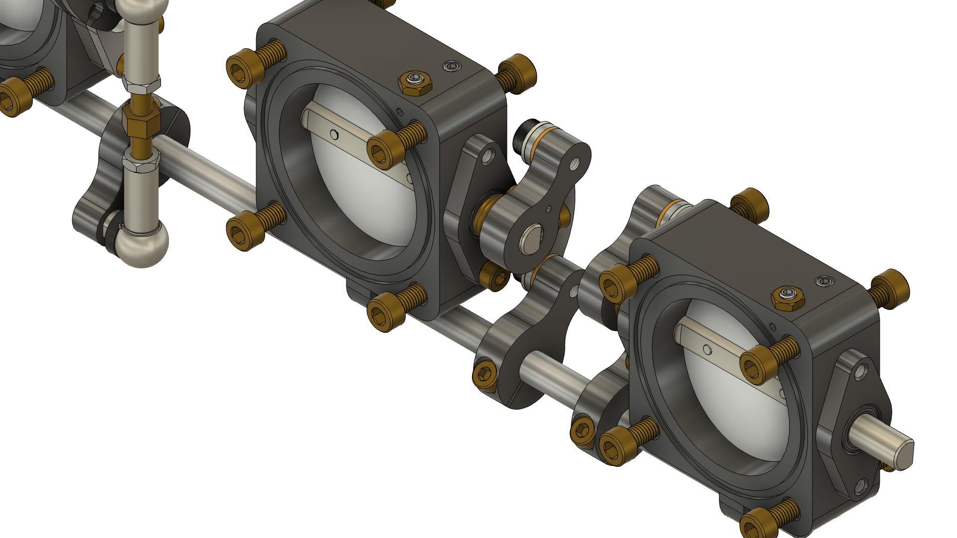
Each throttle has its own return spring on the throttle shaft at the linkage arm (the red arrows). There is not an additional spring on the throttle cable pulley.
For my prototype assembly I plan to just run using a MAF and the stock engine management. Eventually I'd like to put together my own EMS, but don't want the additional variable of the new EMS while trying to prove out the TB's.
The throttles each have adjustability on the linkage arms. The throttle arm that is fixed to the individual throttle shaft is connected via a d-profile arrangement so there is no adjustment here. The adjustment comes from the lower throttle arm connected to the common layshaft. It can be moved to any position necessary to compensate for slight differences in angles of the upper throttle arm due to machining variations and tolerances. The link arms are connected via precision shoulder screws and bushings to eliminate as much slop as possible.
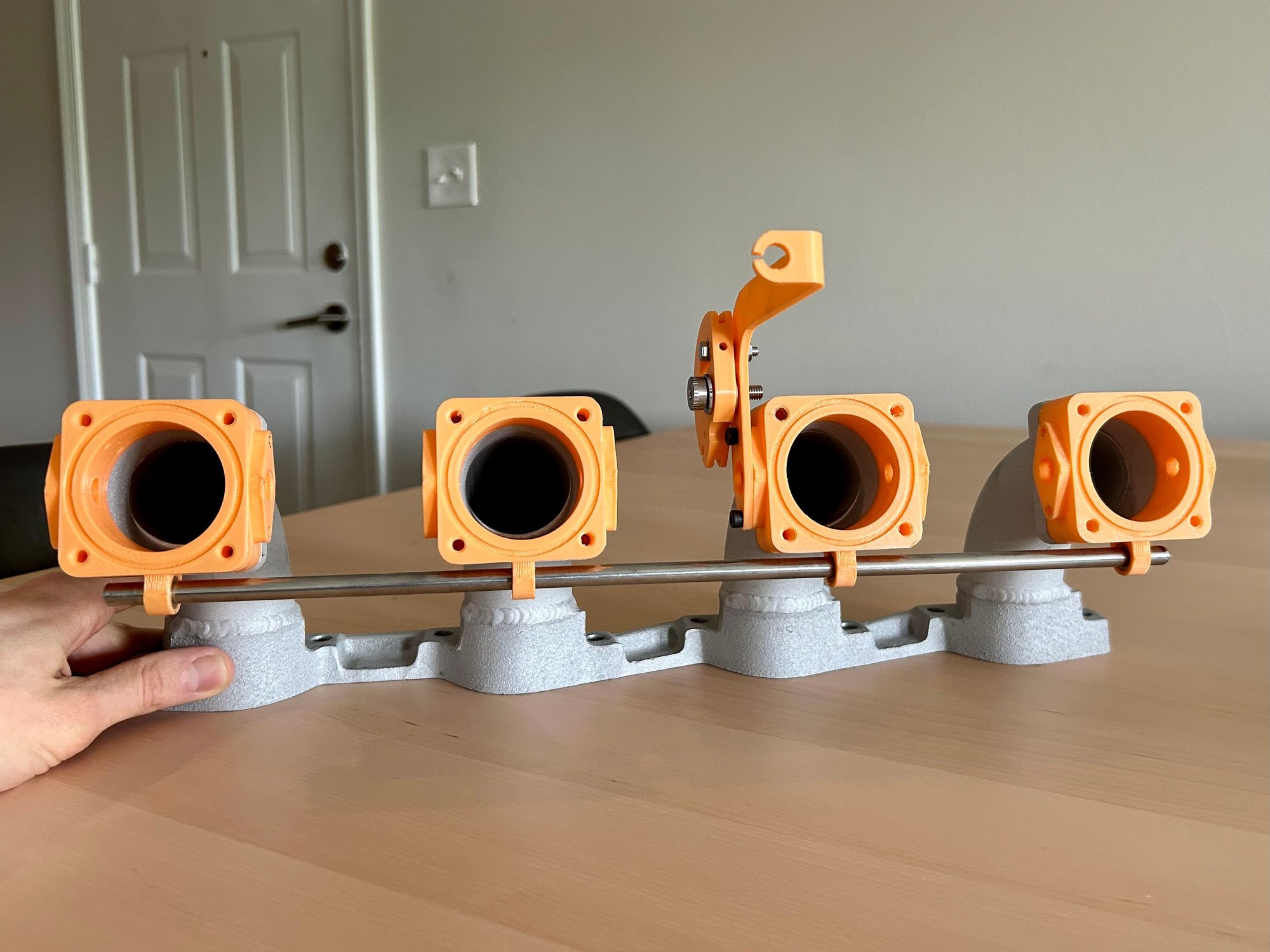
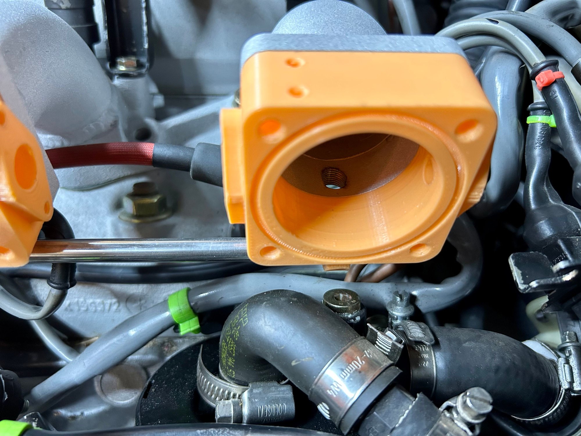
The airflow through each throttle can be adjusted via the cone point set screw/nut on the top of the throttle body. It's just an air bypass like a stock throttle body. This hole you see in the upper right hand corner of the throttle body is covered by the inlet manifold flange when the throttle is mounted. The intent is to make sure all the throttles are completely closed (the return springs will force them into this position) then measure the airflow on each throttle, synchronizing them with the airflow adjustment screw.
This will largely be dictated by what fits under the hood, so it won't be completely optimized. The intent isn't to make this the highest performing system out there, since that would be more dedicated to a race application. I designed it to be a highly-functioning street system that could look almost stock-ish. Because I made it modular, the inlet manifold and throttle bodies could be used with any number of different plenums or open trumpet arrangements.
Totally. Right now I have the ram tube extensions at 60mm so I can still fit a decent sized plenum. I can experiment with something shorter or longer and have considered experimenting with different volume plenums as well to see how the power band shifts up and down the rev range.
I'm actually wondering if I can fit the complete 944S AOS and still keep the filler neck. Any idea if the filler neck clears the rear intake runner on a NA manifold? I know the S manifold has a sharper bend here. It might be something I just need to purchase and test fit. I could possibly "tweak" the rear intake runner a bit for clearance if it wasn't off by too much.
Great comments 962 kid. Thanks!
JRP
I can check this in a couple of days. I have everything needed and 944s engine currently installed. Unless I have to put on the 8 valve head to measure that is
I like this project that you have been working on and have been following with great interest. Im old school with not much in the way of computer skills. I had a career in composite boat building which led me to some messing around with some low volume parts for Porsche mostly race cars. I am familiar with intake resonate plenums as I wanted a system for my 911 race motor. that lead me into a disappointing attempt at low volume manufacturing the parts for resale. my failure was not all on me. It was expected from the venders that were buying from me, that I would put up all the money for tooling as well as all the money to develop a product that they would in fact be able to mark up 100% this worked for a while untill the price of street GT3's rose and which put it expensive for me to use a GT3 for a test mule. That project has since been shelved on the shelf of broken dreams. Fast forward to today, I have a shop by my house and I have I think not sure 7 different kinds of 944 variant cars 3 of which are race cars. except for the 968 and one race car that has a Motec engine management the rest seem to run half *** at best with there old barn door management also when I drive them im always wondering where the leaky gaskets in the back of the car are and why does it seem like my eyse are burning and smell exhaust. Thats where this thread excites me the possible collaberation of the minds to come together to a system that can give the 8valve motor just a bit better life. See I dont know how to tune an ECU or model anything but I do know how to force glue and cloth into a part. my setbacks withthe porsche parts is i dont have anyone to combine the needed drawings and files to run a router hru a block of MDF wood to create a mold All my friends are all to busy with things that make money. I would be able to help with the plenum by means of the tools that I have availible which are the back bones of composite fabrication, Cloth and Glue
I like this project that you have been working on and have been following with great interest. Im old school with not much in the way of computer skills. I had a career in composite boat building which led me to some messing around with some low volume parts for Porsche mostly race cars. I am familiar with intake resonate plenums as I wanted a system for my 911 race motor. that lead me into a disappointing attempt at low volume manufacturing the parts for resale. my failure was not all on me. It was expected from the venders that were buying from me, that I would put up all the money for tooling as well as all the money to develop a product that they would in fact be able to mark up 100% this worked for a while untill the price of street GT3's rose and which put it expensive for me to use a GT3 for a test mule. That project has since been shelved on the shelf of broken dreams. Fast forward to today, I have a shop by my house and I have I think not sure 7 different kinds of 944 variant cars 3 of which are race cars. except for the 968 and one race car that has a Motec engine management the rest seem to run half *** at best with there old barn door management also when I drive them im always wondering where the leaky gaskets in the back of the car are and why does it seem like my eyse are burning and smell exhaust. Thats where this thread excites me the possible collaberation of the minds to come together to a system that can give the 8valve motor just a bit better life. See I dont know how to tune an ECU or model anything but I do know how to force glue and cloth into a part. my setbacks withthe porsche parts is i dont have anyone to combine the needed drawings and files to run a router hru a block of MDF wood to create a mold All my friends are all to busy with things that make money. I would be able to help with the plenum by means of the tools that I have availible which are the back bones of composite fabrication, Cloth and Glue
@autosea Thanks for the response and for the interest in the project! Knowing that I'm ultimately looking at very low volumes here I have toyed around with a lot of different ways to manufacture these components. Right now I'm looking at machined and welded components for the plenum. I can make the shape I want and use the same welder I used for my inlet manifold. Once everything is welded and bead blasted, it resembles a casting, which is really the look I was going for.
I do like the idea of the carbon intakes, and while I can model things to death and make up manufacturing drawings out the wazoo (this is what I do for a day job), doing things in carbon definitely eludes me. A someday collaboration of some sort is certainly a possibility worth exploring after I complete the initial design and testing.
 04-09-2023, 09:29 AM