When you click on links to various merchants on this site and make a purchase, this can result in this site earning a commission. Affiliate programs and affiliations include, but are not limited to, the eBay Partner Network.
JRP, one concern I've got: I'm a CFD engineer in my day job. I've got more experience with liquids, but this plenum design looks a bit risky to me. I'm afraid that cylinders 1 & 4 will get less air flow as the middle two.
You could do an oval inlet on the plenum side which then tapers to a circular cross-section to connect to the silicon hose as you have it now. I personally like this option you showed more, because it's better aerodynamically, plumbing and packaging is also easier.
If you're interested, I'll talk to colleagues who have experience with intake simulations and I could run this for you. Let me know!
Additionally, I'd want to have an air filter box roughly at the location of the stock NA one. If you'd like, I could help designing that and we could also simulate it.
Regarding AOS: wouldn't it be easier to just create a design where the filler neck fits between the plenum and the brake booster, then 3D print it?
Hi Ish-
Thanks again for the feedback.
Early on in the design phase I performed some basic static simulations on various plenum designs to determine what was best. With a static simulation, your hunch is correct and the air velocity was greater to cylinders 2 and 3 than it was to 1 and 4 with the center feed. Then I realized that a static analysis wasn’t really accurate since the intake valves aren’t all open at the same time, and that a transient analysis would be required to really see how each runner performs. I’m no CFD expert so I opted not to try the transient analysis and instead based the design on the center feed with the theory being that although it may not be the most optimal, it’s worked for various manufacturers and aftermarket suppliers over the years with (I think) good results.
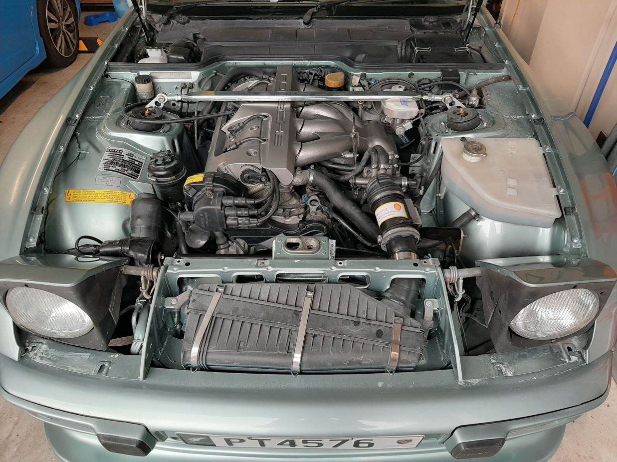
There isn’t quite enough space between the plenum and the brake booster to fit an oil cap as it stands. I have the thought of making a multi-jet fusion or SLS printed S-bend in PA12 glass-filled nylon so that it stands up to the oil and heat, but for now I just wanted to get something on there that would allow me to cap the AOS so I can run the engine.
So we appear to have a big vacuum leak, or so I think. Idle is high at around 1500-1600 RPM and it sure sounds like a leak somewhere. Let’s see if I successfully attached the video or not…
Some observations…
The revs hang, which I think is due to the vacuum leak.
The car will basically drive itself with no throttle input due to the high idle.
When I turn on the A/C, the idle comes down to 1000-1100 RPM.
I’m not making much vacuum currently and thus don’t really have brakes.
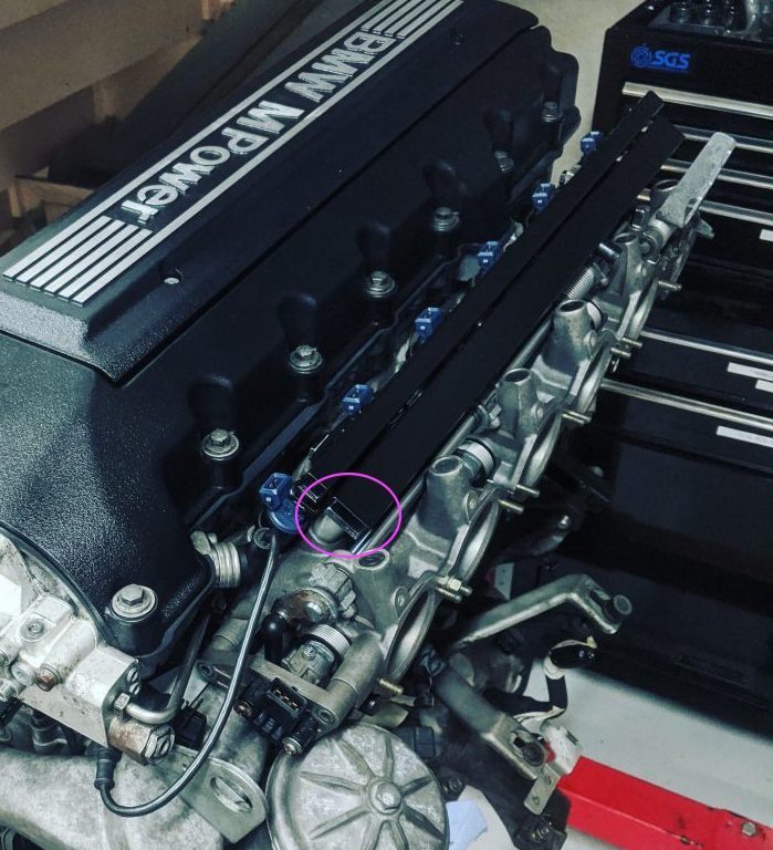
My initial thought was that maybe I installed the IAC valve backwards, but looking at the photo of the plumbing under the plenum, I’m not so sure this is the case. It’s worth checking tomorrow, but I’m also wondering if I just unplug the valve for now as well to eliminate that as a potential problem.
Maybe my throttle plates aren’t sealing so well in the throttle body and too much air is getting around them? This would explain the high idle (I think).
It’s possible I have a leak coming from somewhere else, but I really tried to make sure every threaded NPT connection was sealed well with Teflon thread sealant and that everything was tight.
Where are some other spots I should check or does anyone have some other suggestions?
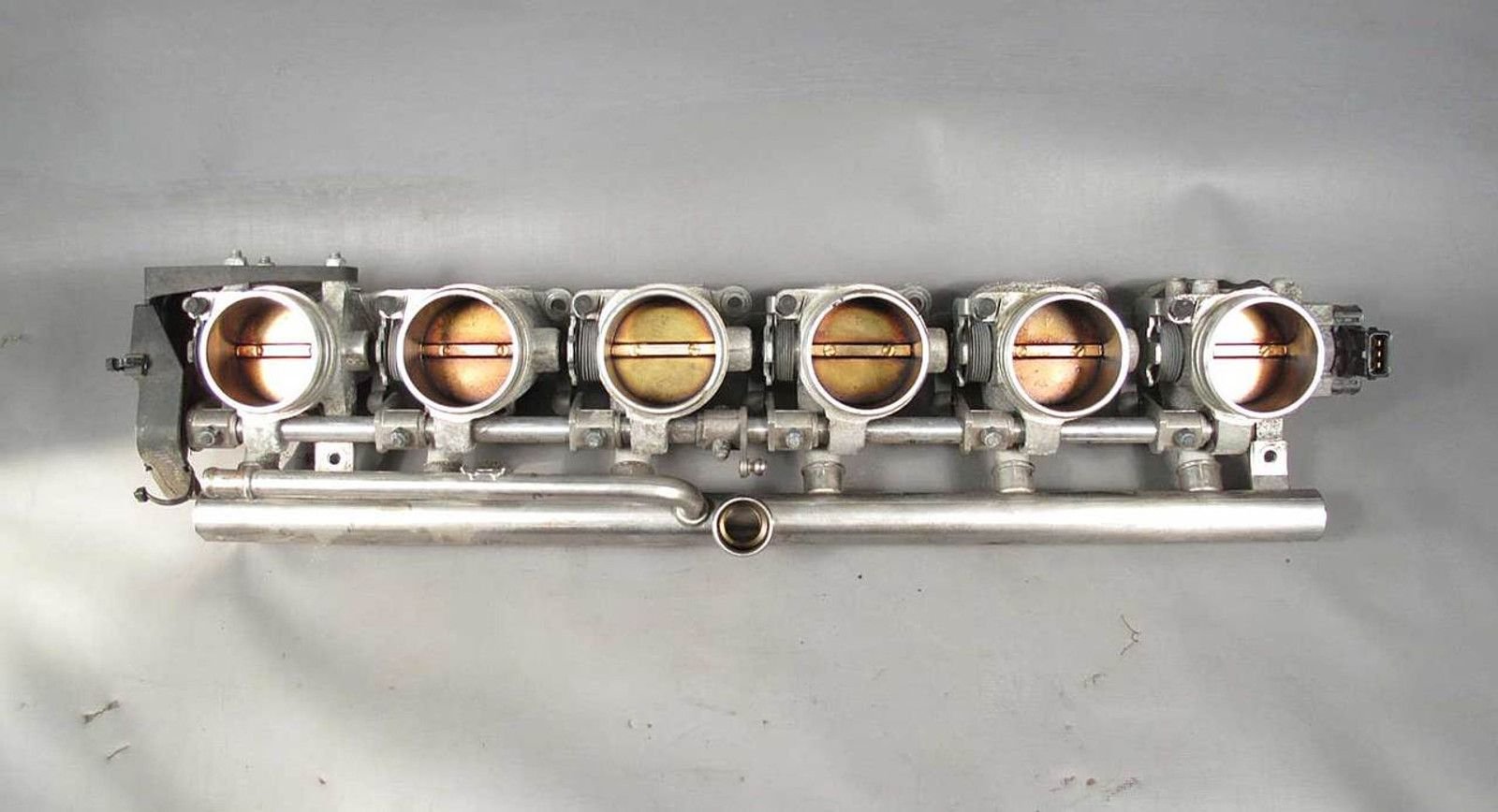
@T&T Racing Thanks for the info. For the design shown above, I was basically using the design from the BMW S54 engine to collect into the common vacuum rail and then a fitting on either end of the rail would be plumbed to the brake booster and the IAC valve.
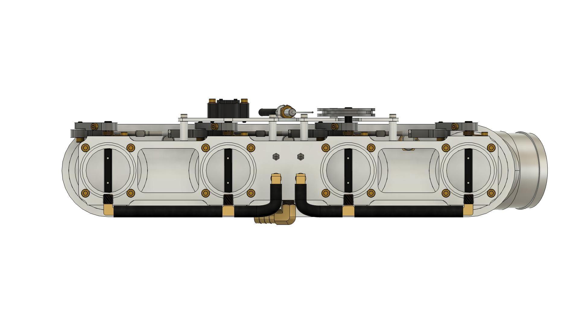
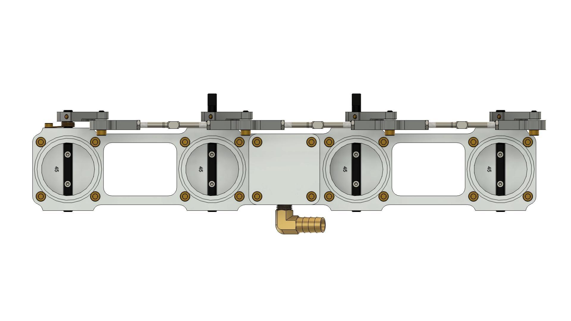
For the new design, I have cylinders 1-2 and 3-4 plumbed in parallel and then plumbed into a small collector between cylinders 2 and 3. I can (hopefully) use this collector to supply the vacuum for the brake booster as well as the vacuum signal for the fuel pressure regulator and even a map sensor. You can see the plumbing a little better in these images below.
In case there are no leaks, I assume you would need a (bigger) vacuum plenum. Alternatively, for the brake booster, you could install an EV vacuum pump.
Here is a good read :
"On a common plenum setup, the pulses are damped by the large volume and the fact that all the cylinder tracts are connected by the arms (or is it legs) of the intake plenum. With ITBs, the problem is you are reading each individual cylinder, and there is no averaging effect... unless you try to mimic the common plenum."
Finally, I suggest going the Megasquirt or VEMS route to get the full benefit of your development. Years ago, I did some headwork, intake manifold, camshaft, and flywheel modifications on my 944. With the old, worn AFM, the engine mapping didn't fit anymore. So, I went the VEMS route and couldn't be happier now.
Hmm, are you sure the return springs are strong enough? Couldn't the engine vacuum open the throttle blades just a hair? Maybe try to push on your synchro rod to force-close the TBs.
Another thing could be to disconnect all vacuum ports at the bottom of the intake runners, block them off and see what happens.
Actually, an easy test could be if you disconnect the brake booster hose while the engine is running. If practically nothing happens, then air is bypassing the throttle bodies.
I removed the IAC valve circuit to eliminate that as a potential culprit and didn’t really see a change. So I started to check for other vacuum leaks with the starter fluid method and didn’t find any, which I guess is good since that means the plumbing is in good shape.
Took a closer look at the linkage by moving it back and forth more by hand and noticed that one of the throttle shafts was slipping in the throttle arm, so there were times where this throttle butterfly appears to have not been closing all the way. @jeyjey called it on that one. Loosened up all the throttle arms and readjusted everything including the springs to make sure none of the springs were getting “lazy” at the end of their travel. Got all of the throttle butterflies closing as good as possible.
The high idle still persists, but is maybe a 100-200 RPM lower. I have better vacuum at the brake booster now as the brakes work a bit better. I am of the belief that these throttle butterflies just aren’t sealing well enough against the throttle body. I had this concern in the beginning since I felt they could have fit a bit tighter, and it appears the concern was legitimate. Looks like to solve this problem, or at least test the theory, I will need to purchase some better quality butterflies than what I can make.
I’m feeling a little burned out after some hot days in the garage and am tempted to put the stock intake back on while I try to sort out the butterflies. This would at least give me a car I can still drive in the mean time. I dunno yet, but either way I’m not going to touch it again until next weekend. Looks like it won’t make it to the Deutsche Classic after all. Big bummer.
Hey @JRP944,
* You've been mentioning how you'll have vacuum for a MAP. Will it be possible to run these with an IAT & MAP setup? Would be super convenient, since I've got the Augtronic ECU.
Cheers & keep up the superb work!
I recently talked to Tom at Augment, he said that Augtronic can be run off of the TPS rather than MAP for ITB use.
I removed the IAC valve circuit to eliminate that as a potential culprit and didn�t really see a change. So I started to check for other vacuum leaks with the starter fluid method and didn�t find any, which I guess is good since that means the plumbing is in good shape.
Took a closer look at the linkage by moving it back and forth more by hand and noticed that one of the throttle shafts was slipping in the throttle arm, so there were times where this throttle butterfly appears to have not been closing all the way. @jeyjey called it on that one. Loosened up all the throttle arms and readjusted everything including the springs to make sure none of the springs were getting �lazy� at the end of their travel. Got all of the throttle butterflies closing as good as possible.
The high idle still persists, but is maybe a 100-200 RPM lower. I have better vacuum at the brake booster now as the brakes work a bit better. I am of the belief that these throttle butterflies just aren�t sealing well enough against the throttle body. I had this concern in the beginning since I felt they could have fit a bit tighter, and it appears the concern was legitimate. Looks like to solve this problem, or at least test the theory, I will need to purchase some better quality butterflies than what I can make.
I�m feeling a little burned out after some hot days in the garage and am tempted to put the stock intake back on while I try to sort out the butterflies. This would at least give me a car I can still drive in the mean time. I dunno yet, but either way I�m not going to touch it again until next weekend. Looks like it won�t make it to the Deutsche Classic after all. Big bummer.
JRP
Bummer mate! You must feel a bit heartbroken, I imagine.
You could test the butterfly theory, I reckon, if you remove your cone filter and just close the silicon hose with your palm. If your idle drops, then you were correct.
Don't worry too much, I'm sure you're going to find a brilliant solution!
Originally Posted by Tony5
I recently talked to Tom at Augment, he said that Augtronic can be run off of the TPS rather than MAP for ITB use.
 07-05-2024, 05:57 PM