

1965 Imp 911 - a baby 911 in making....
The following users liked this post:
Edward (09-04-2021)
 09-12-2021 | 06:00 AM
#17
Thread Starter
Advanced
Joined: Aug 2020
Posts: 73
Likes: 70
From: Motueka, New Zealand
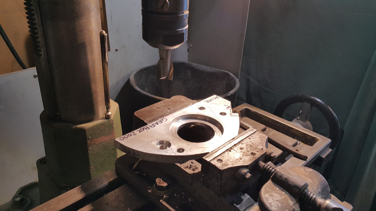
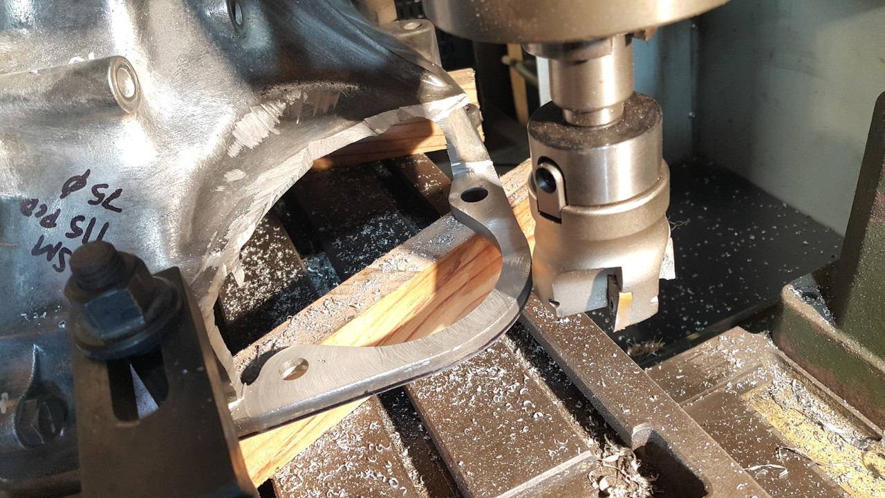
Starter motor time. I had bought a Subaru leone 1.8 starter from the fella I'd got the gearboxes and 1.8 ring gear from. Made sense to use all the same bits. Only thing I'd have to do was move the mounting face for the starter forwards towards the engine to suit the new ring gear position on my home made flywheel...
.jpg)
Easy as I thought and I had it all planned out. I shall start at dawn!
However that's not what happened once I got a friendly query from a fella about the starter motor turning the engine the wrong way.
Oh yeah. Of course it will do that. Silly me. Yay.
So after a few ideas and suggestions from various folk I had a few options. My first option was to mount the Subaru starter on the front of the bellhousing adaptor, facing backwards. Essentially turn it 180 degrees and it would spin the Honda engine in the required anti-clockwise direction I needed. But would it fit?
Yes it does...
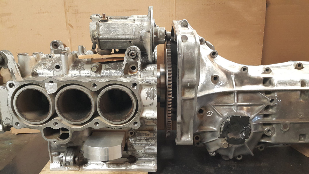
It wouldn't be too tricky to mount and on extension the pinion almost lined up perfectly with the ring gear. It sat down in place quite low too. So this solution was a strong contender. But it had a couple of weaknesses that meant it went to the back burner.
One: the ring gear would need turning around so the leads shaped into the teeth faced the pinion. Turning it round and having the pinion strike it from the opposite side then meant that the step I had machined into the flywheel would have been on the wrong side and the gear could potentially work off over time. I was reluctant about the idea I could add a few welds, as some folk will do, because it adds stress risers, could affect the balance. I really didn't want to muck about with the ring gear.
Two: having a fairly large ugly starter motor plonked right there on the top of the motor was something I never had in my minds pictures of how I wanted the engine bay to look. It would be right where I might want some linkages for the itbs, possibly a centrally mounted plenum between the itbs and there was also going to be some water pipes around that area too.
So back to the other options- the main one being to look for a suitable Honda starter that's mounted from the gearbox side or a starter from any standard clockwise rotating engine that mounts from the front. The pinion had to have the same pitch and ideally the same tooth count. I did some research and it seemed that all the Japanese cars of this era all shared the same pinion pitch and were all around the 9 or 10 teeth. This was handy indeed.
Off to the wreckers then...
I went through the various shelves of starters, starting with Honda and found a possible candidate within a couple of minutes. Feeling pretty satisfied with my find I still double checked the other shelves just in case there was something even better but eventually I was spotted skipping out of the door happy with my Honda Civic/accord starter.
Back home I looked at my booty. Subaru one is on the left...
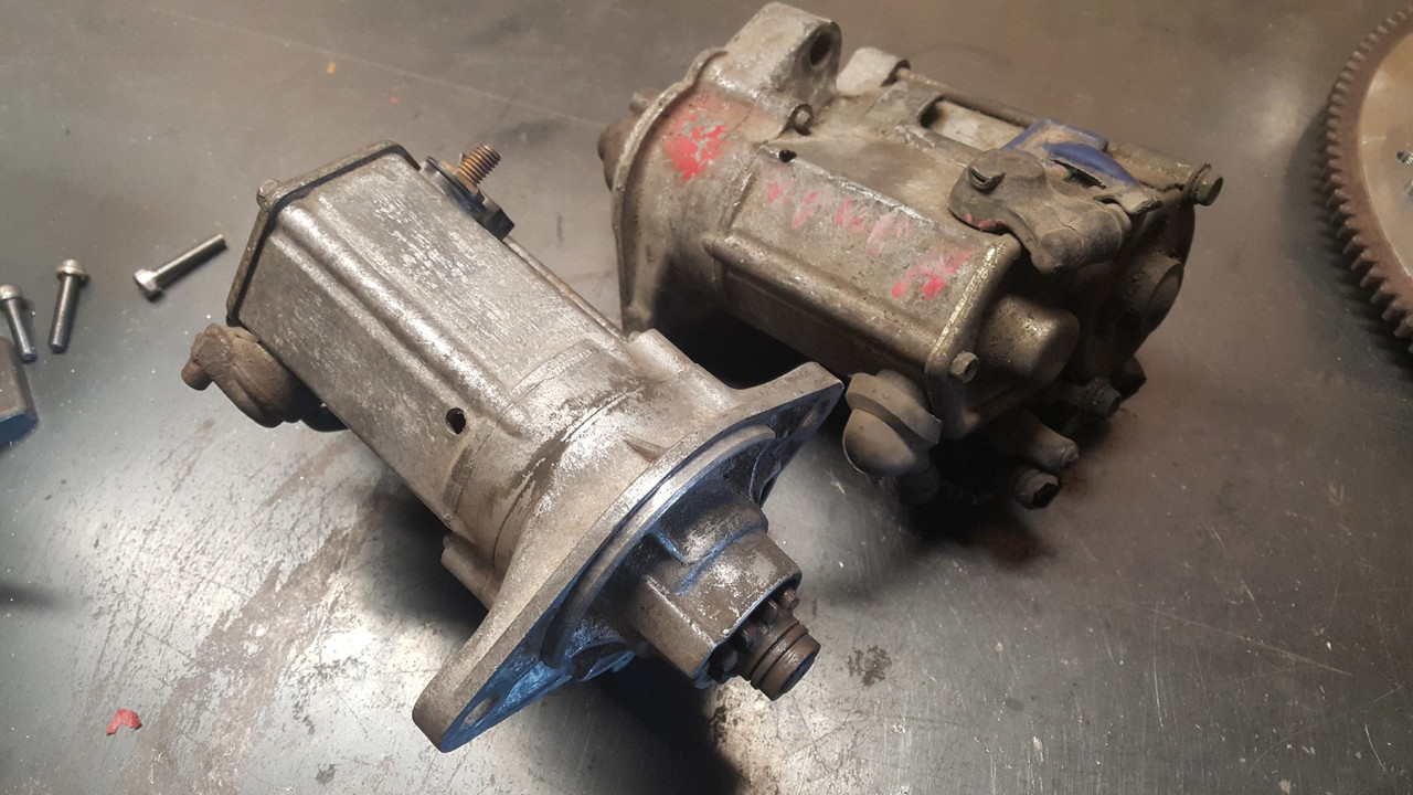
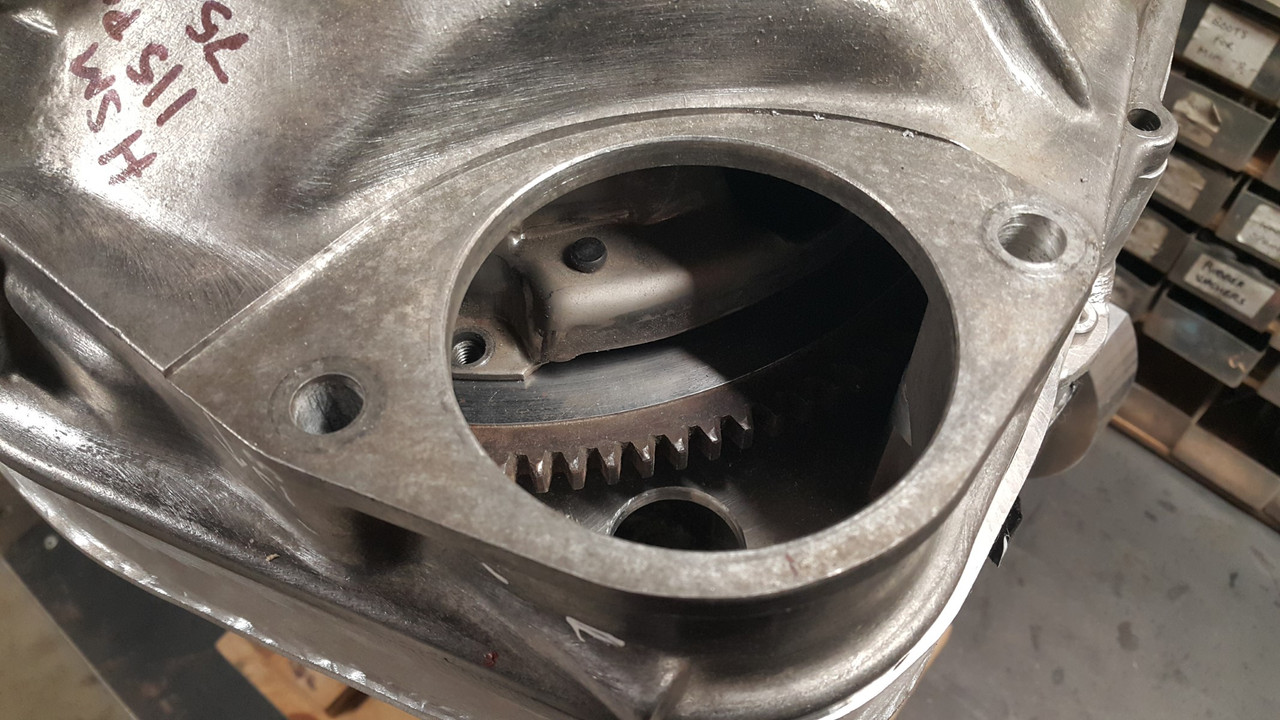
They were so close but not close enough. The Honda item has a smaller diameter 'locating spigot' that centralises it in the hole on the mounting face of the bell housing.
.jpg)
This was a better turnout than it being bigger than the hole though! I would machine the hole in the plate to suit the new starter, which I was going to have to do for the original plan using the Subaru one anyway.
The holes for the starter mounting bolts, that go through the bell housing into the engine, were 5mm closer at about 115mm and they were also offset to one side, not in line with the starters centreline.
.jpg)
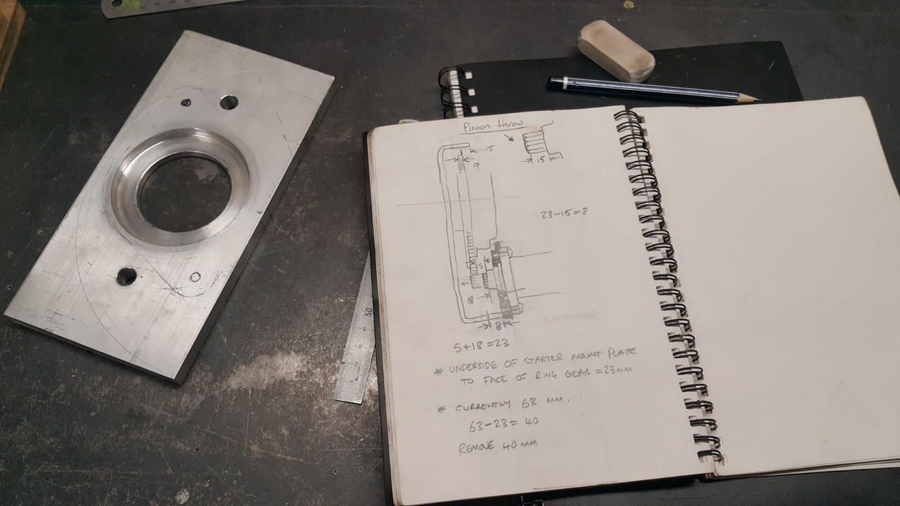
This was handy though because I could then have separate bolts holding the bell housing and room to turn the Honda starter about its axis, having the solenoid positioned in the least obstructive way. A plan was forming in my head. I took some measurements, did some scribbles and it all looked like it should work ok...
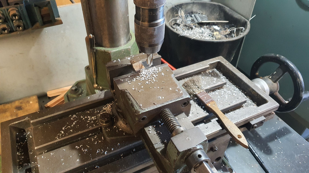
I had already bought a hefty bit of 12mm plate for the Subaru starter repositioning and luckily it was still going to work with the new starter. I swapped the 4 jaw chuck onto the lathe and set it up. Drilled a big hole...
.jpg)
Bored the hole out to suit the Honda starter spigot...
.jpg)
.jpg)
Marked and drilled holes to suit...
.jpg)
Recessed and spot faced one of the holes for the bellhousing to the engine bolts that just happened to slightly clash with a bit of the starter casting.
So I now had a plate that the starter fitted neatly into, with not a hint of slop. The bolt holes lined up perfectly with the bellhousing bolt holes so lining the starter up the correct distance out from the ring gear. Now I need to move the face of this plate closer to the engine...
So I cut a big lump of alloy from the bellhousing with a grinder and a hacksaw...
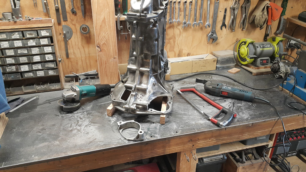
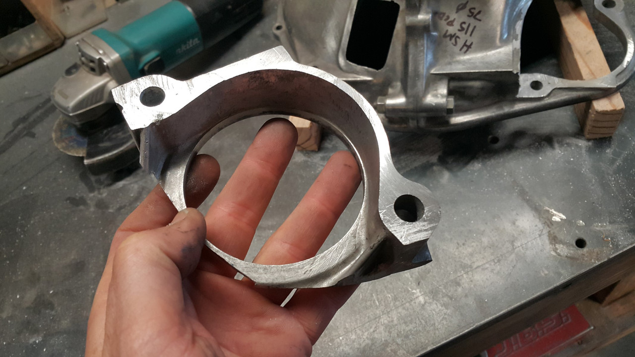
This allowed me to move the plate closer and let the pinion fully engage with the ring gear...
I tested the fit of the starter...
The height was good but I wanted it to be perfectly parallel to the face of the flywheel so I really had to mill it. Luckily I was just able to squeeze the gearbox into a position on the mill that allowed me to face it perfectly...
I must have some pretty honed hacksaw skills because I only needed to skim off about .75mm to get it flat. Sweet.
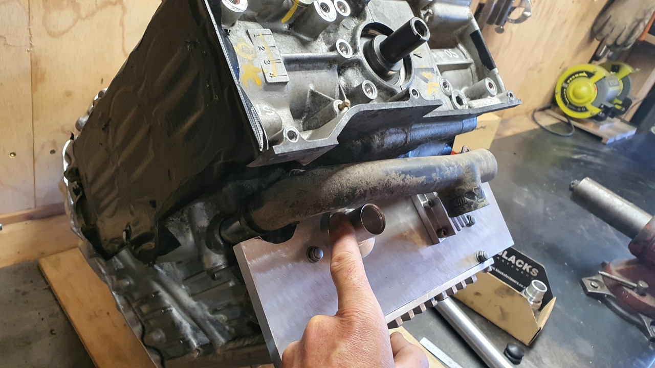
Now I bolted the plate in place, then the starter and tested it...
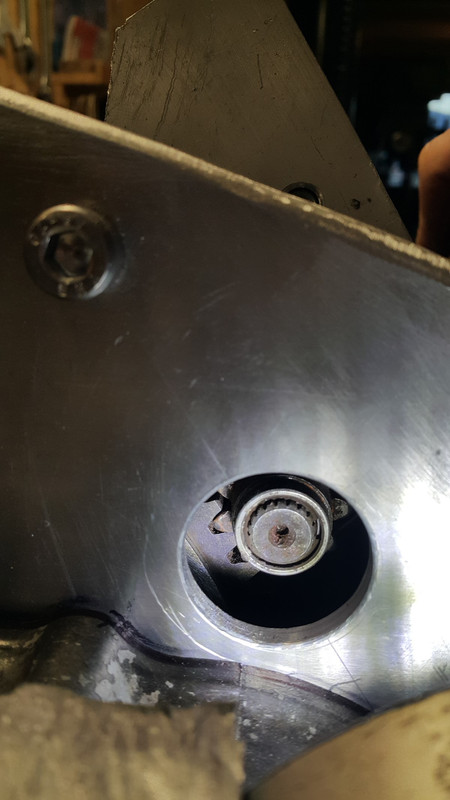
Oh I forgot to mention that once I had decided I was going to use a starter mounted in the original position I popped a hole through the adaptor plate in line with the starter pinion. This was to allow me to check the pinion mesh...
I was super happy with the mesh so I marked the excess on the plate to be trimmed off and gave it a hair cut in the bandsaw...
.jpg)
I also milled out the back of the plate where it just clashed with the rivets and pressings on the outer edge clutch pressure plate. Bolted it back in and welded it up, taking lots of care to avoid any chance of movement or warping. It went well..
.jpg)
Added some little filler plates to tie it in neatly and gave it a tickle with a flap disc...
.jpg)
.jpg)
Bolted the starter back in, stood back and admired it all, really happy that one of the trickier jobs had been completed and that the starter was sitting in there very neatly and tucked away nicely, no higher than the top of the bellhousing...
.jpg)
Next step was to make a cover for the 'front' of the engine, adding a connecting link between the oil filter outlet and the main oil way into the engine, a filling point for the sump, a dipstick and allocations for engine mounts to suit a cross member.
Still lots of work to do but I'm getting closer...
Easy as I thought and I had it all planned out. I shall start at dawn!
However that's not what happened once I got a friendly query from a fella about the starter motor turning the engine the wrong way.
Oh yeah. Of course it will do that. Silly me. Yay.
So after a few ideas and suggestions from various folk I had a few options. My first option was to mount the Subaru starter on the front of the bellhousing adaptor, facing backwards. Essentially turn it 180 degrees and it would spin the Honda engine in the required anti-clockwise direction I needed. But would it fit?
Yes it does...
It wouldn't be too tricky to mount and on extension the pinion almost lined up perfectly with the ring gear. It sat down in place quite low too. So this solution was a strong contender. But it had a couple of weaknesses that meant it went to the back burner.
One: the ring gear would need turning around so the leads shaped into the teeth faced the pinion. Turning it round and having the pinion strike it from the opposite side then meant that the step I had machined into the flywheel would have been on the wrong side and the gear could potentially work off over time. I was reluctant about the idea I could add a few welds, as some folk will do, because it adds stress risers, could affect the balance. I really didn't want to muck about with the ring gear.
Two: having a fairly large ugly starter motor plonked right there on the top of the motor was something I never had in my minds pictures of how I wanted the engine bay to look. It would be right where I might want some linkages for the itbs, possibly a centrally mounted plenum between the itbs and there was also going to be some water pipes around that area too.
So back to the other options- the main one being to look for a suitable Honda starter that's mounted from the gearbox side or a starter from any standard clockwise rotating engine that mounts from the front. The pinion had to have the same pitch and ideally the same tooth count. I did some research and it seemed that all the Japanese cars of this era all shared the same pinion pitch and were all around the 9 or 10 teeth. This was handy indeed.
Off to the wreckers then...
I went through the various shelves of starters, starting with Honda and found a possible candidate within a couple of minutes. Feeling pretty satisfied with my find I still double checked the other shelves just in case there was something even better but eventually I was spotted skipping out of the door happy with my Honda Civic/accord starter.
Back home I looked at my booty. Subaru one is on the left...
They were so close but not close enough. The Honda item has a smaller diameter 'locating spigot' that centralises it in the hole on the mounting face of the bell housing.
This was a better turnout than it being bigger than the hole though! I would machine the hole in the plate to suit the new starter, which I was going to have to do for the original plan using the Subaru one anyway.
The holes for the starter mounting bolts, that go through the bell housing into the engine, were 5mm closer at about 115mm and they were also offset to one side, not in line with the starters centreline.
This was handy though because I could then have separate bolts holding the bell housing and room to turn the Honda starter about its axis, having the solenoid positioned in the least obstructive way. A plan was forming in my head. I took some measurements, did some scribbles and it all looked like it should work ok...
I had already bought a hefty bit of 12mm plate for the Subaru starter repositioning and luckily it was still going to work with the new starter. I swapped the 4 jaw chuck onto the lathe and set it up. Drilled a big hole...
Bored the hole out to suit the Honda starter spigot...
Marked and drilled holes to suit...
Recessed and spot faced one of the holes for the bellhousing to the engine bolts that just happened to slightly clash with a bit of the starter casting.
So I now had a plate that the starter fitted neatly into, with not a hint of slop. The bolt holes lined up perfectly with the bellhousing bolt holes so lining the starter up the correct distance out from the ring gear. Now I need to move the face of this plate closer to the engine...
So I cut a big lump of alloy from the bellhousing with a grinder and a hacksaw...
This allowed me to move the plate closer and let the pinion fully engage with the ring gear...
I tested the fit of the starter...
The height was good but I wanted it to be perfectly parallel to the face of the flywheel so I really had to mill it. Luckily I was just able to squeeze the gearbox into a position on the mill that allowed me to face it perfectly...
I must have some pretty honed hacksaw skills because I only needed to skim off about .75mm to get it flat. Sweet.
Now I bolted the plate in place, then the starter and tested it...
Oh I forgot to mention that once I had decided I was going to use a starter mounted in the original position I popped a hole through the adaptor plate in line with the starter pinion. This was to allow me to check the pinion mesh...
I was super happy with the mesh so I marked the excess on the plate to be trimmed off and gave it a hair cut in the bandsaw...
I also milled out the back of the plate where it just clashed with the rivets and pressings on the outer edge clutch pressure plate. Bolted it back in and welded it up, taking lots of care to avoid any chance of movement or warping. It went well..
Added some little filler plates to tie it in neatly and gave it a tickle with a flap disc...
Bolted the starter back in, stood back and admired it all, really happy that one of the trickier jobs had been completed and that the starter was sitting in there very neatly and tucked away nicely, no higher than the top of the bellhousing...
Next step was to make a cover for the 'front' of the engine, adding a connecting link between the oil filter outlet and the main oil way into the engine, a filling point for the sump, a dipstick and allocations for engine mounts to suit a cross member.
Still lots of work to do but I'm getting closer...
Last edited by yoeddynz; 09-12-2021 at 06:16 AM.
12-29-2021 | 05:22 AM
#18
Thread Starter
Advanced
Joined: Aug 2020
Posts: 73
Likes: 70
From: Motueka, New Zealand
Back on the chain gang !
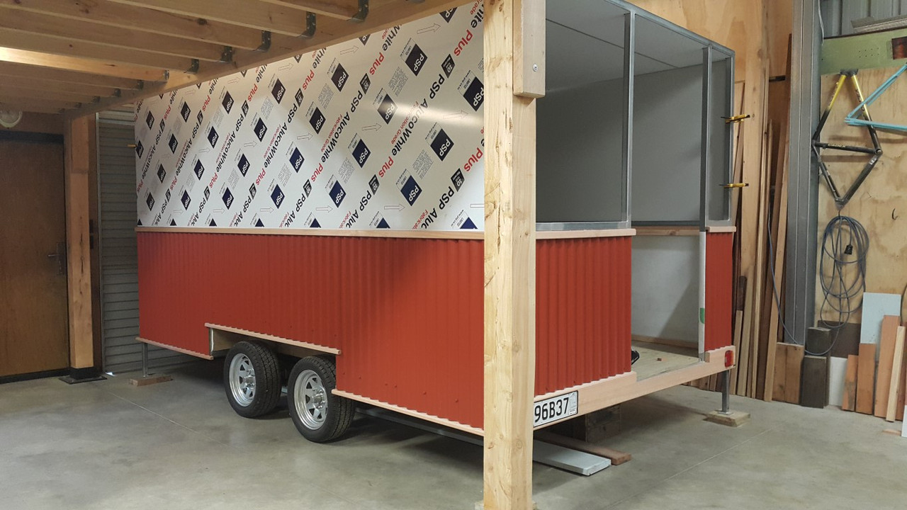
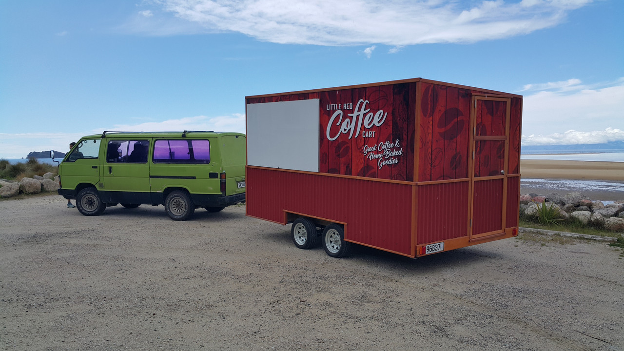
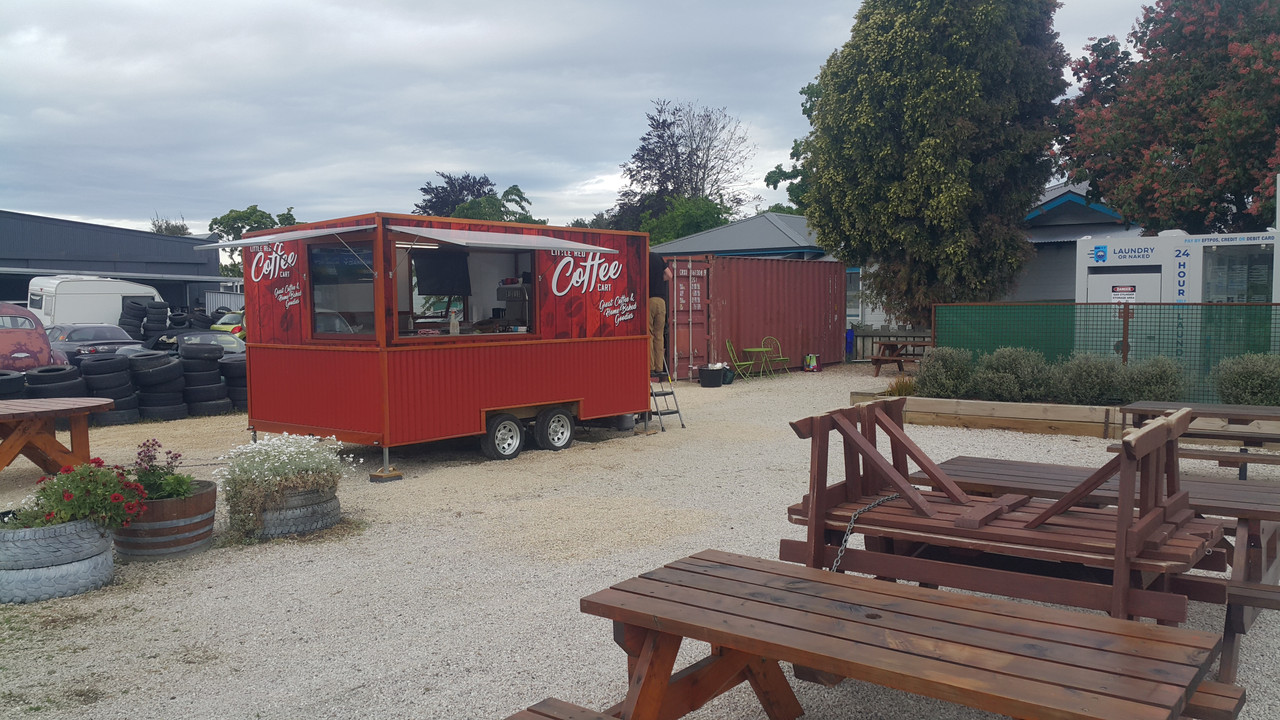
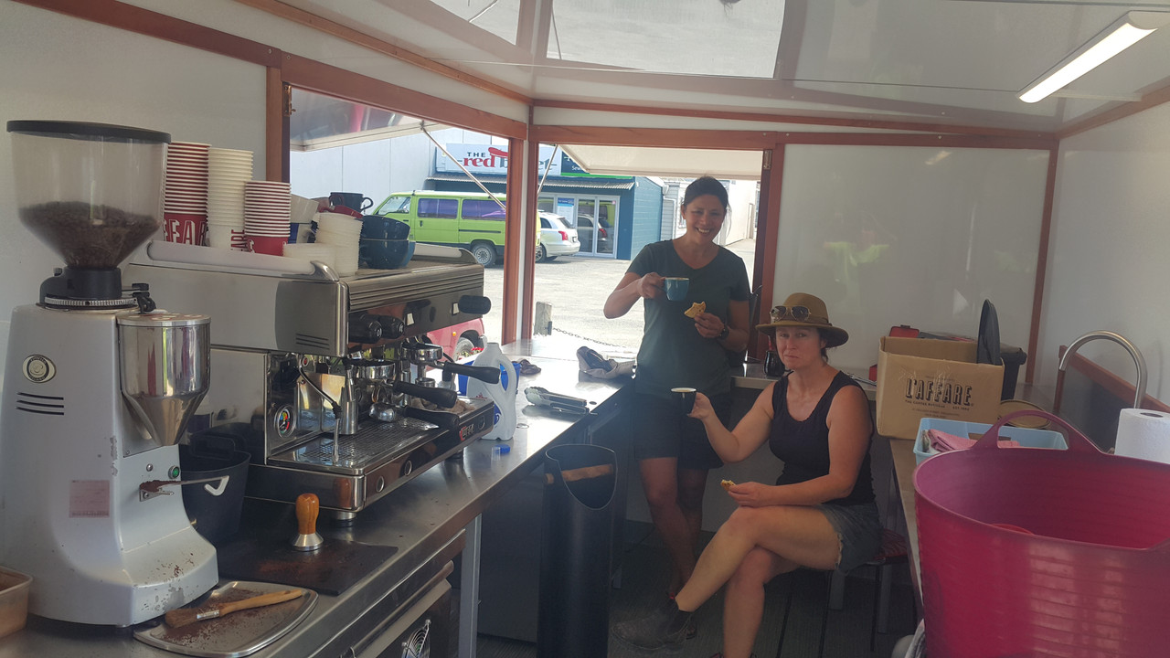
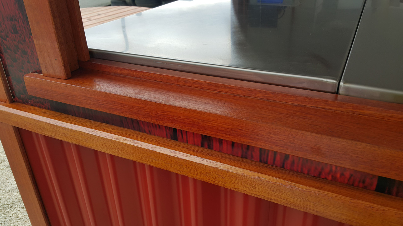
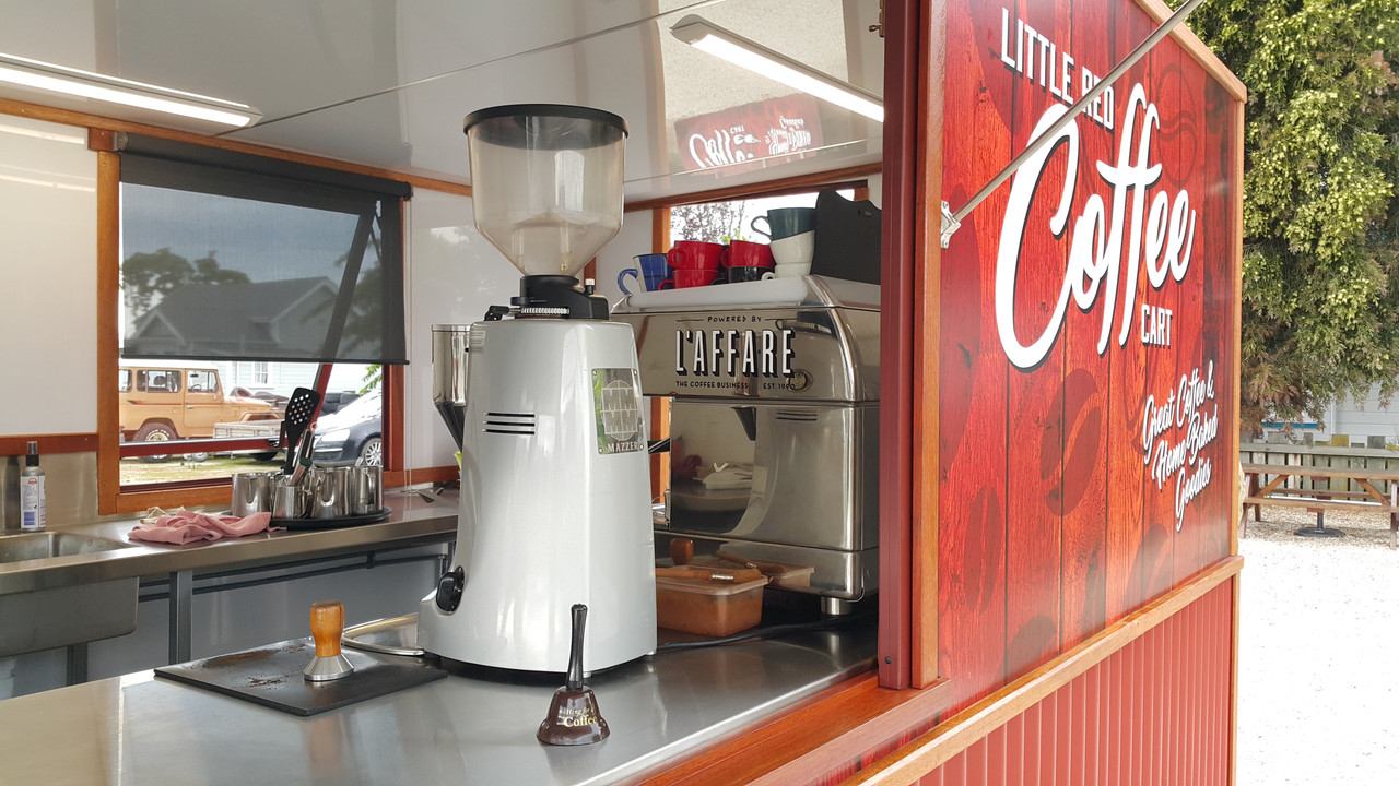
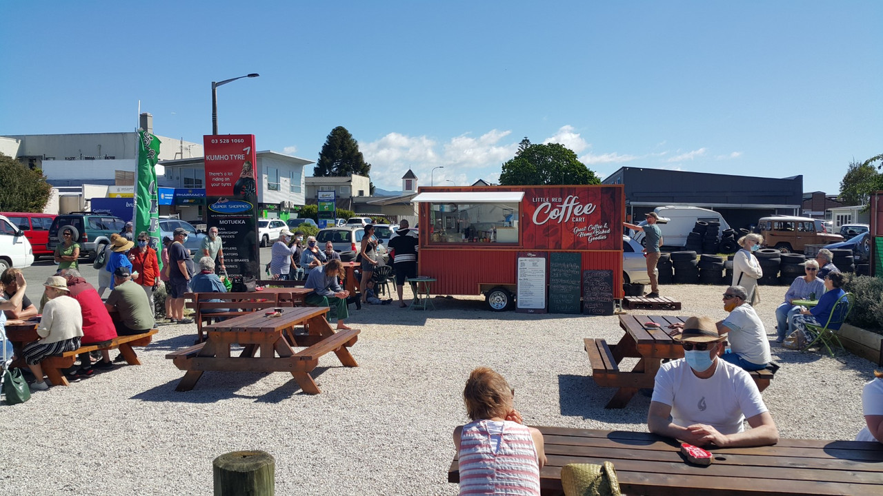
Yep. I'm back into this project. Its been a hectic busy last few months. Well for me, but others would probably laugh at my work levels. The last update was in September and both Hannah and I were pretty busy building a custom coffee cart for a customer. It was a fair old mission not helped by that pesky lockdown stalling a load of stuff ordered, including some double glazed window materials from Auckland. We put in some hard efforts to get the thing built and ready in time for the agreed date and managed it with a 2am finish on the last day before delivery. I was well chuffed with the cart we built and the customer is soooo happy with her new cafe ! All fully insulated, huge windows that roll away into the walls, loads of stainless benching and a lovely outside wood framing we made using Eucalyptus timber then oiled.
Here's some pics of the build...
Phew. Check that one off the whiteboard of jobs. Loads more work to chip through and we are now onto the steel framework for a local ladies housetruck. So I am going to do my best to just put down the tools, lock my bicycles away so I cant be tempted to just go riding and instead do more on this engine swap.
Most recent bits I have done are as follows.
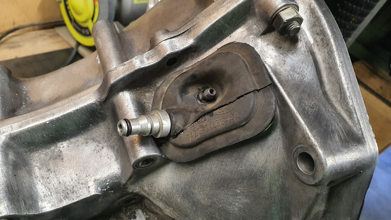
I wanted to finish off the oil system. The internal stuff from the pick up to the pump and filter was sorted. Now I needed to get the oil from the filter to the engine. Luckily, well I kind of planned around it, there is a hole left where gear selector shaft went. This was ideal to pass a pipe back from the filter block outlet towards the front/belt end of the engine. But it needed to be bigger with some clearance. One big drill bit later...
.jpg)
.jpg)
next up was a plate to cover the front. What used to be here was a cast front cover, much deeper obviously because I have lopped off a huge chunk of engine casing. It housed the oil filter, now moved to the side. Instead of that I now needed a flat plate of thick alloy that will serve several things. The engine mounts, most likely typical compression bobbins, will be mounted off it. There has to be a way to get the oil from the pipe coming from the filter block to head back into the main oil feed hole higher in the block. Finally I need somewhere to put oil into the engine and also to check the oil level.
I started with a plate of alloy I roughly cut to size. Drilled it to suit the holes in the block that the old front cover mounted to. I then drilled a hole in it to suit the oil feed pipe. This was a hole perfectly located to make sure the pipe would line up with the filter transfer block nice and square. Because I'm using the O rings that Honda used throughout the original system. There is a small tolerance for being out of square with these but I might as well get it as close as I can.
.jpg)
I then needed to make a bolt on block that would take the oil from this pipe end and direct it through another hole in the plate which locates right over another O ring sealed port into the engines main oil way, just as the original front cover did.
I started with some more chunks of alloy and made a thousands of teeny tiny chunks of alloy with the tablesaw...
.jpg)
.jpg)
One of the blocks was then milled out to suit the pipe outlet and oilway inlet sizes. I also used a tiny little slot drill to add a groove to help keep the sealant in place..
.jpg)
.jpg)
.jpg)
Flipped it over and took more material away. Added some cooling grooves. But really.. come on. They were more just so it looked a bit nicer than just being a lump of alloy. Why not..
.jpg)
.jpg)
Clamped it down onto the front plate and drilled mounting holes...
.jpg)
There's a nice amount of room to still use the original honda cooling hose if I want but I may well do something else when I get to that bit- depends on my cross member design and engine mounts etc..
.jpg)
.jpg)
Next up was how to get oil in place! I needed a filler point. The original filler and dipstick are in the wrong spot and kind of chopped out. I could have made a dipstick to suit the now chopped down dipstick housing but that's at the rear/flywheel end of the engine. With the engine turned round 180 degrees that puts it under the parcel shelf and would mean reaching over what ever induction setup I use (cough*ITBS*cough) so that's not cricket.
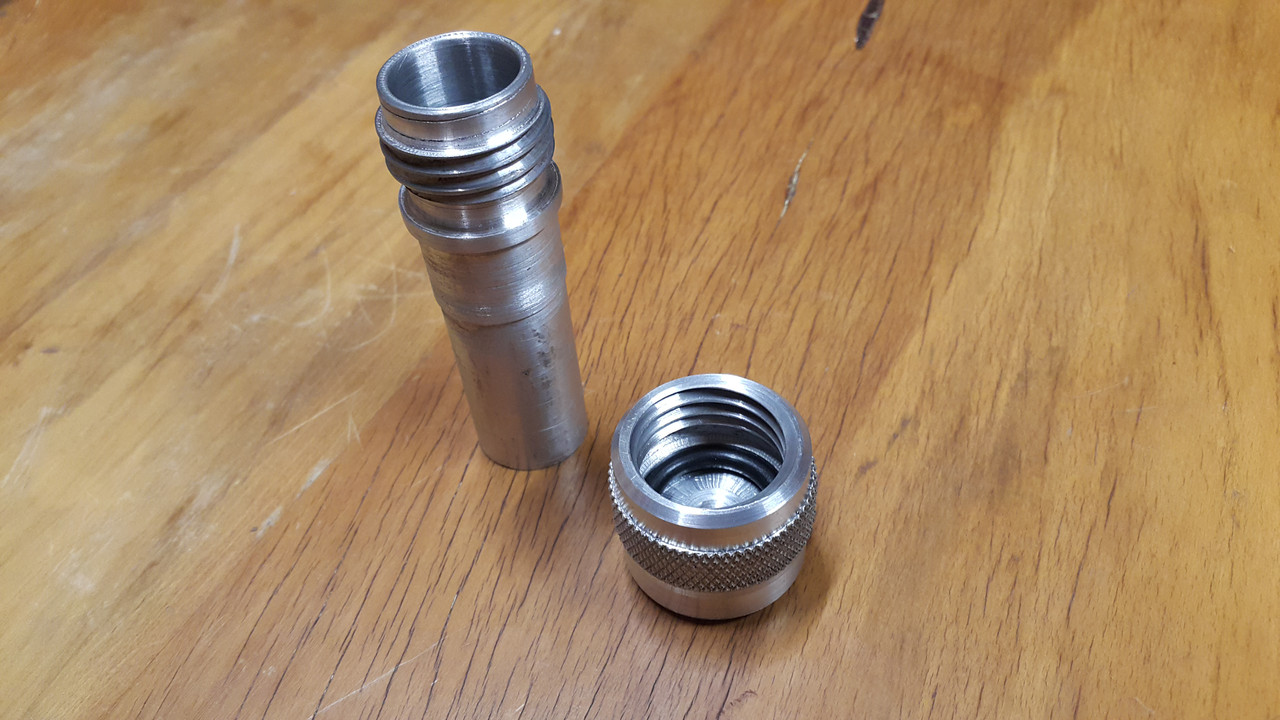
A filler tube, right at the front, but actually now the back, of the engine with a combined dipstick under the cap made more sense.
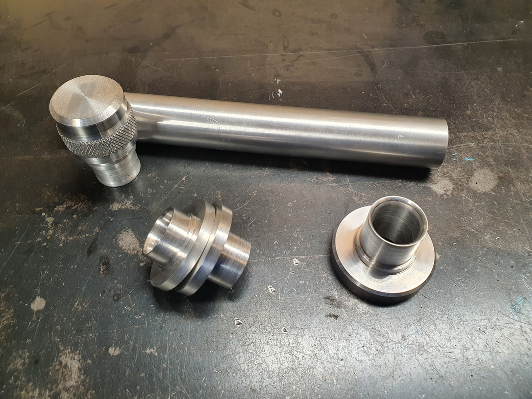
I rummaged through my collection of alloy..
.jpg)
Playtime in the lathe...
and out popped this...
..into which oil will pour as such....

Now I needed some more bits to hold it in the right place so I made these flanges to suit more pipe.
Once I know what I'm doing with the cooling pipes etc I'll cut the pipe to suit and epoxy it into the flanges. I ideally need the main large flange to bolt over a hole below the oil level height - which I have roughly worked out allowing for about 4.5 litres thereabouts. This pipe and cap will be right there, on view, easy to get to at the engine bay opening. The two smaller flanges are so I can remove the upright pipe to allow for the cambelt covers to be removed, or so its not there liable for getting damaged when removing and moving the engine about.
I did think about being super silly and adding a sight glass to the pipe. Or use some thin glass or plastic tube. I then even thought about being really silly and adding an led light into the pipe to light up the oil.
But oil does not stay honey clean does it. So a neat little dipstick under the cap will do.
Lastly I needed to bolt the sump cover in place. I had to think carefully about bolt placement for sealing purposes and get the bolts square. This sump plate is going to have to be sealed well because there is no usual high sided sump like most cars. Hence I built it rigid to help against flex. Good quality sealant will be the order of the day*
To get the bolt holes square I had to do this...
.jpg)
Impy sat outside looking in at his new heart being crafted (said like some car obsessed bloke who anthropomorphises his cars)...
.jpg)
Well then. That's it. Crikey. Another wall of text. I hope you enjoyed my ramblings. I promise I'll put more effort into working on this (but it is summer after all..)
*It will leak. Its a British car. Its destined to leak.
Yep. I'm back into this project. Its been a hectic busy last few months. Well for me, but others would probably laugh at my work levels. The last update was in September and both Hannah and I were pretty busy building a custom coffee cart for a customer. It was a fair old mission not helped by that pesky lockdown stalling a load of stuff ordered, including some double glazed window materials from Auckland. We put in some hard efforts to get the thing built and ready in time for the agreed date and managed it with a 2am finish on the last day before delivery. I was well chuffed with the cart we built and the customer is soooo happy with her new cafe ! All fully insulated, huge windows that roll away into the walls, loads of stainless benching and a lovely outside wood framing we made using Eucalyptus timber then oiled.
Here's some pics of the build...
Phew. Check that one off the whiteboard of jobs. Loads more work to chip through and we are now onto the steel framework for a local ladies housetruck. So I am going to do my best to just put down the tools, lock my bicycles away so I cant be tempted to just go riding and instead do more on this engine swap.
Most recent bits I have done are as follows.
I wanted to finish off the oil system. The internal stuff from the pick up to the pump and filter was sorted. Now I needed to get the oil from the filter to the engine. Luckily, well I kind of planned around it, there is a hole left where gear selector shaft went. This was ideal to pass a pipe back from the filter block outlet towards the front/belt end of the engine. But it needed to be bigger with some clearance. One big drill bit later...
next up was a plate to cover the front. What used to be here was a cast front cover, much deeper obviously because I have lopped off a huge chunk of engine casing. It housed the oil filter, now moved to the side. Instead of that I now needed a flat plate of thick alloy that will serve several things. The engine mounts, most likely typical compression bobbins, will be mounted off it. There has to be a way to get the oil from the pipe coming from the filter block to head back into the main oil feed hole higher in the block. Finally I need somewhere to put oil into the engine and also to check the oil level.
I started with a plate of alloy I roughly cut to size. Drilled it to suit the holes in the block that the old front cover mounted to. I then drilled a hole in it to suit the oil feed pipe. This was a hole perfectly located to make sure the pipe would line up with the filter transfer block nice and square. Because I'm using the O rings that Honda used throughout the original system. There is a small tolerance for being out of square with these but I might as well get it as close as I can.
I then needed to make a bolt on block that would take the oil from this pipe end and direct it through another hole in the plate which locates right over another O ring sealed port into the engines main oil way, just as the original front cover did.
I started with some more chunks of alloy and made a thousands of teeny tiny chunks of alloy with the tablesaw...
One of the blocks was then milled out to suit the pipe outlet and oilway inlet sizes. I also used a tiny little slot drill to add a groove to help keep the sealant in place..
Flipped it over and took more material away. Added some cooling grooves. But really.. come on. They were more just so it looked a bit nicer than just being a lump of alloy. Why not..
Clamped it down onto the front plate and drilled mounting holes...
There's a nice amount of room to still use the original honda cooling hose if I want but I may well do something else when I get to that bit- depends on my cross member design and engine mounts etc..
Next up was how to get oil in place! I needed a filler point. The original filler and dipstick are in the wrong spot and kind of chopped out. I could have made a dipstick to suit the now chopped down dipstick housing but that's at the rear/flywheel end of the engine. With the engine turned round 180 degrees that puts it under the parcel shelf and would mean reaching over what ever induction setup I use (cough*ITBS*cough) so that's not cricket.
A filler tube, right at the front, but actually now the back, of the engine with a combined dipstick under the cap made more sense.
I rummaged through my collection of alloy..
Playtime in the lathe...
and out popped this...
..into which oil will pour as such....
Now I needed some more bits to hold it in the right place so I made these flanges to suit more pipe.
Once I know what I'm doing with the cooling pipes etc I'll cut the pipe to suit and epoxy it into the flanges. I ideally need the main large flange to bolt over a hole below the oil level height - which I have roughly worked out allowing for about 4.5 litres thereabouts. This pipe and cap will be right there, on view, easy to get to at the engine bay opening. The two smaller flanges are so I can remove the upright pipe to allow for the cambelt covers to be removed, or so its not there liable for getting damaged when removing and moving the engine about.
I did think about being super silly and adding a sight glass to the pipe. Or use some thin glass or plastic tube. I then even thought about being really silly and adding an led light into the pipe to light up the oil.
But oil does not stay honey clean does it. So a neat little dipstick under the cap will do.
Lastly I needed to bolt the sump cover in place. I had to think carefully about bolt placement for sealing purposes and get the bolts square. This sump plate is going to have to be sealed well because there is no usual high sided sump like most cars. Hence I built it rigid to help against flex. Good quality sealant will be the order of the day*
To get the bolt holes square I had to do this...
Impy sat outside looking in at his new heart being crafted (said like some car obsessed bloke who anthropomorphises his cars)...
Well then. That's it. Crikey. Another wall of text. I hope you enjoyed my ramblings. I promise I'll put more effort into working on this (but it is summer after all..)
*It will leak. Its a British car. Its destined to leak.
12-29-2021 | 03:46 PM
#20
Thread Starter
Advanced
Joined: Aug 2020
Posts: 73
Likes: 70
From: Motueka, New Zealand
@Shawn Stanford Thanks for the compliment.
However I think you are probably doing just fine though- certainly earning a fair bit more coin than I considering your impressive garage of Porsches! I'm having to stick with rusty old english cars...
Just like you probably think your job is easy for you, after many years developing your computing skills, I also see the work I do as pretty easy too. Its certainly fun! If you ever have a chance to throw an old lathe and Mill into your workshop go for it. Even just machining little bits and bobs here and there is very satisfying and the skills can develop quickly.
Alex
01-01-2022 | 12:36 PM
#21
Three Wheelin'
Joined: Jul 2014
Posts: 1,340
Likes: 638
From: arizona
another tech guy here who is very impressed with your skills!
(it's interesting, intricate work in tech but there aren't really any physical artifacts. nothing you can easily visually admire like a fabricated piece of metal.)
looking forward to more pics of your progress.
(it's interesting, intricate work in tech but there aren't really any physical artifacts. nothing you can easily visually admire like a fabricated piece of metal.)
looking forward to more pics of your progress.
The following users liked this post:
yoeddynz (01-03-2022)
The following users liked this post:
69-912-SWT (01-07-2022)
01-03-2022 | 01:00 PM
#23
Burning Brakes
Joined: Mar 2018
Posts: 881
Likes: 139
From: N. Texas
The following users liked this post:
yoeddynz (01-13-2022)
01-03-2022 | 01:34 PM
#24

Rennlist Member
Joined: May 2010
Posts: 1,083
Likes: 321
i could righteously ruin some great metal if i had those tools...
please do keep posting - this is one of the more interesting threads going right now and I for one would love to see it through. Great work!!
please do keep posting - this is one of the more interesting threads going right now and I for one would love to see it through. Great work!!
The following users liked this post:
yoeddynz (01-13-2022)

The following users liked this post:
yoeddynz (01-13-2022)
The following users liked this post:
yoeddynz (01-13-2022)
01-07-2022 | 04:18 PM
#27
Nordschleife Master
Joined: Oct 2006
Posts: 7,446
Likes: 63
wow, you sir a a madman... and I love it. Please do keep up with the posts.
I did machining work when I was working during college... after graduation I went the engineering route... till this day, It was one of the most creative experience I've had... and Im sure I just barely scratched the surface then.
I did machining work when I was working during college... after graduation I went the engineering route... till this day, It was one of the most creative experience I've had... and Im sure I just barely scratched the surface then.
The following users liked this post:
yoeddynz (01-13-2022)
01-13-2022 | 01:26 PM
#28
Thread Starter
Advanced
Joined: Aug 2020
Posts: 73
Likes: 70
From: Motueka, New Zealand
Hey all- thanks for the kind words. Its also nice to know that my ramblings are being appreciated even though the subject is not a Porsche.
Well- I like to think of it as a baby Porsche for the cash poor :-)
Anyway- here's an update...
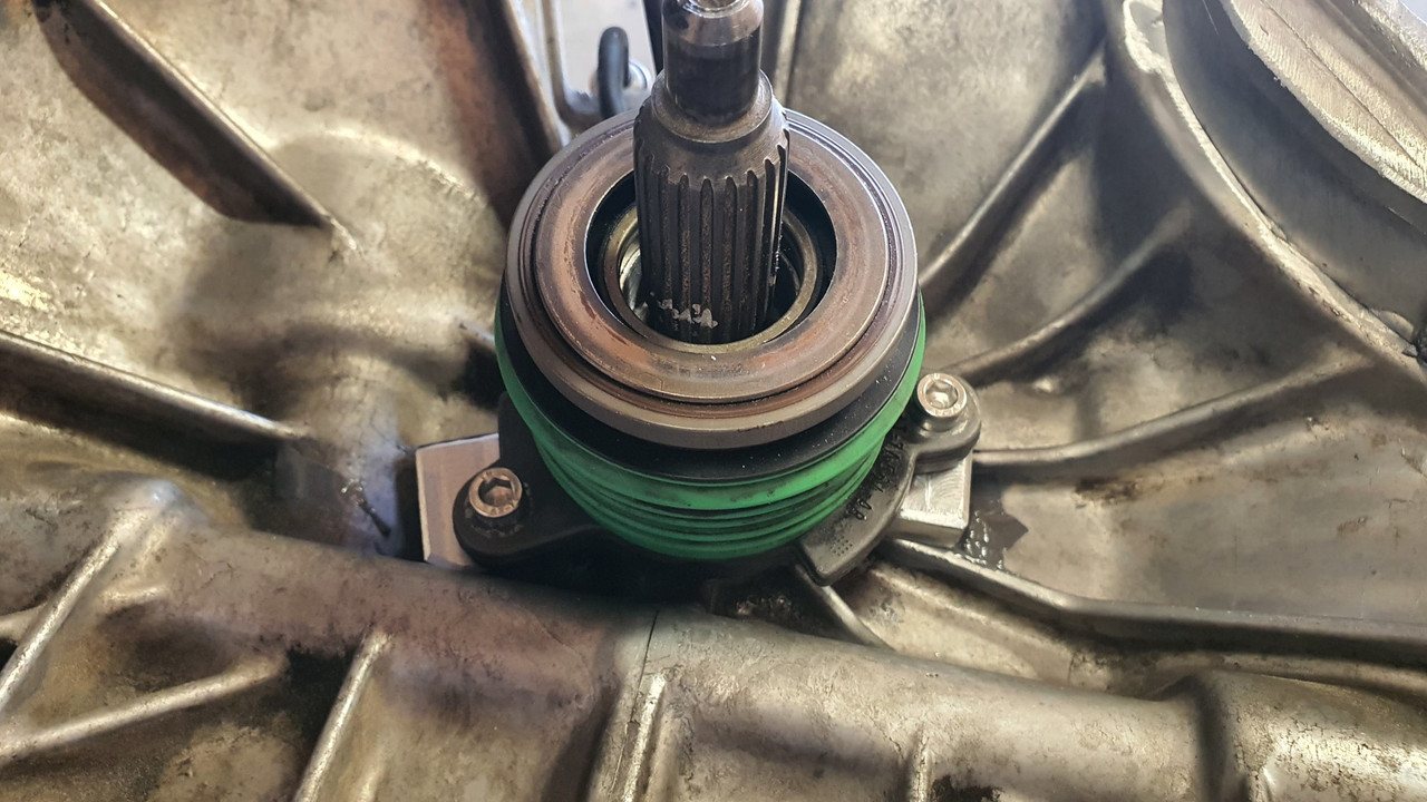
Next step in the puzzle was to sort out a clutch release system. I had a couple of options that could work. I could use the stock Subaru fork but it was not ideal for two reasons ;
1: It would need a the release bearing carrier adapting to take a larger diameter bearing that would suit the Honda pressure plate fingers.
2: Its pivot location, being a centre mounted fulcrum point, would require a slave cylinder that pushed it towards the front of the car. This is because originally the Leone the transmission came from uses a clutch cable. I'd being using a hydraulic slave and it would have to be mounted up high, over the engine. Probably clash with the underside of the parcel shelf and would definitely look ugly there.
Option two was to use the Ford Mundano concentric slave cylinder I have had stashed away for ages, acquired with the Duratec engine I was going to fit into the Viva wagon many moons ago.
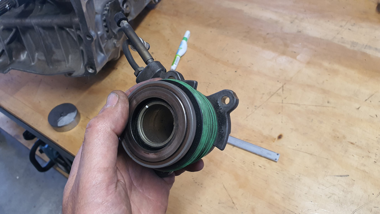
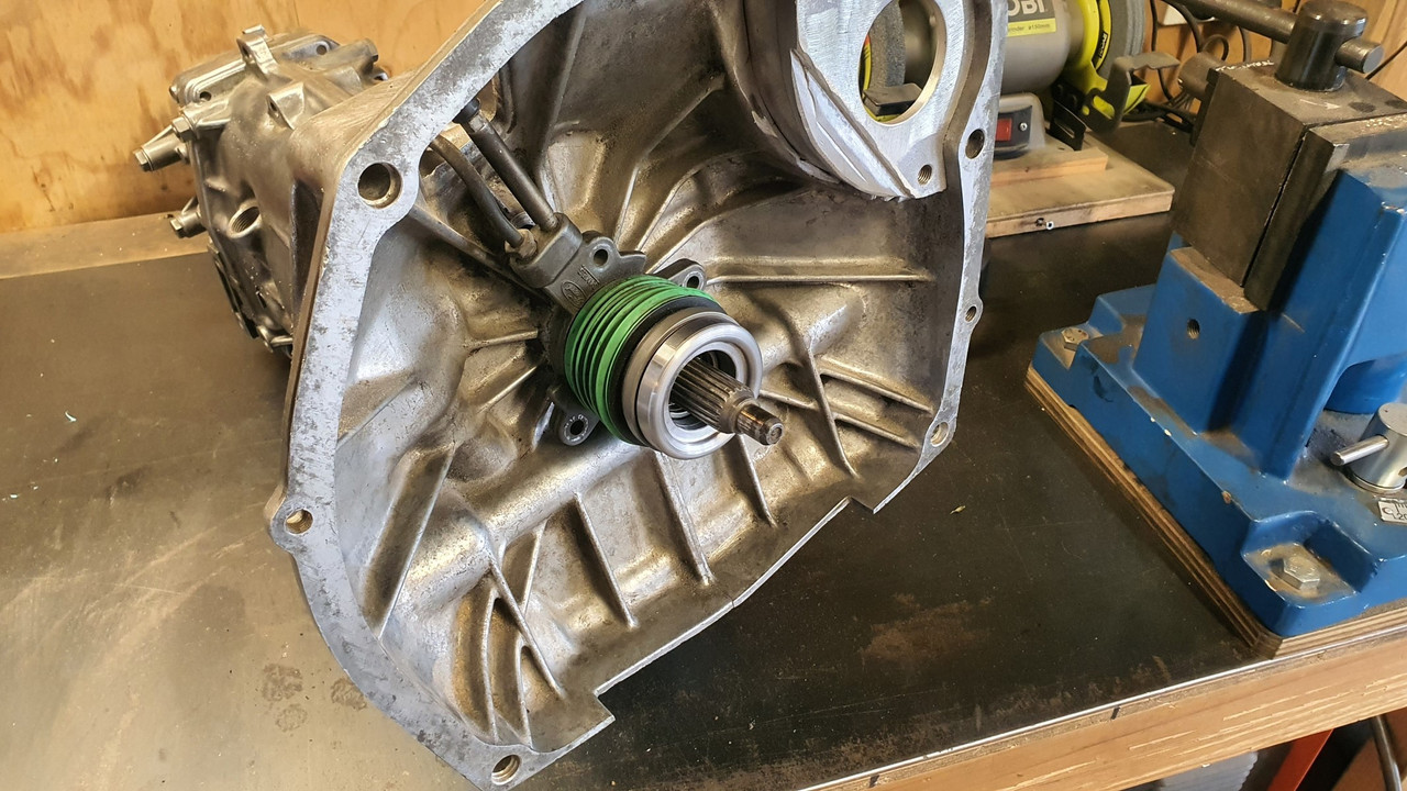
This certainly seemed the most sensible option because it fitted into the location almost perfectly...
The pipes even pop out through the Subaru release fork hole like it was made for it...
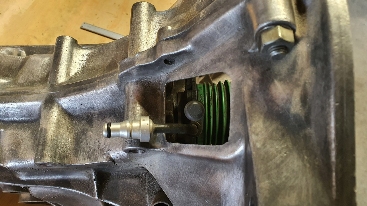
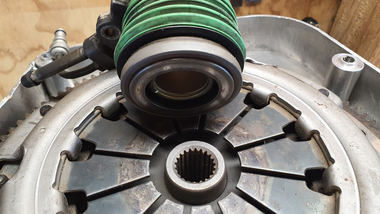
But it was still going to require a little work. First off is that it has a flat bearing face, made to suit curved diaphragm spring ends. It was also too small in diameter to suit the fingers.
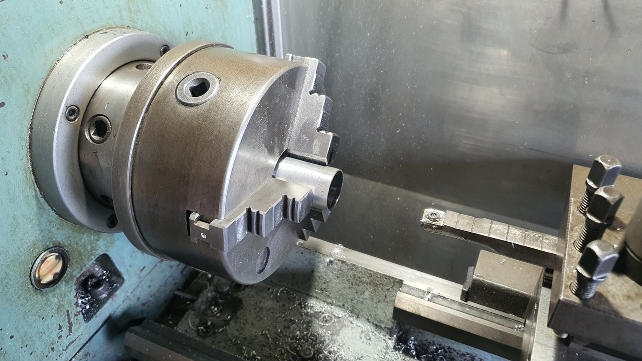
So a lump of steel was plucked from the store...
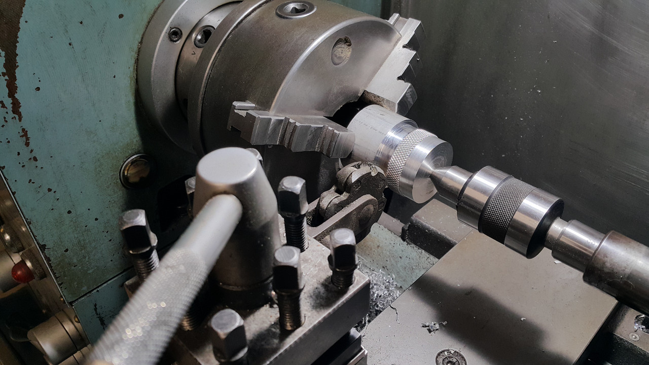
There was just enough room between the bearing face and the 'slidey hub' bit that the bearing hydraulics slide in and out on for me to machine a locating stub onto the bit of steel...
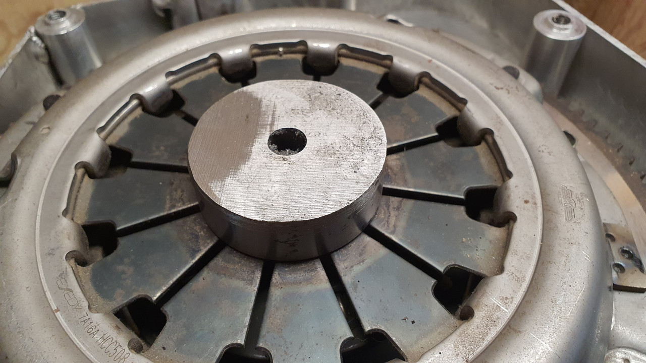
With that being a perfect fitting locating point the other side was machined with a radialised face to suit the flat fingers. The end result looks like this..
This will be stuck in place onto the release bearing face with something like loctite 601. It cant go anywhere anyway.
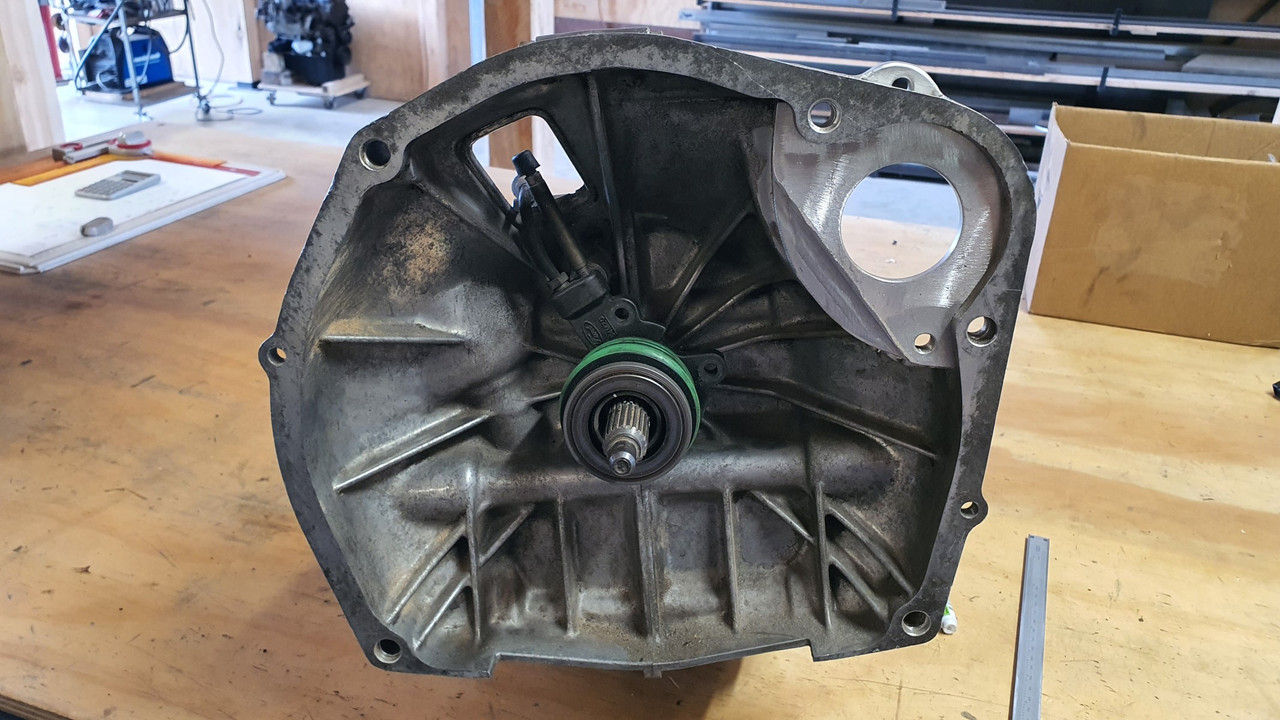
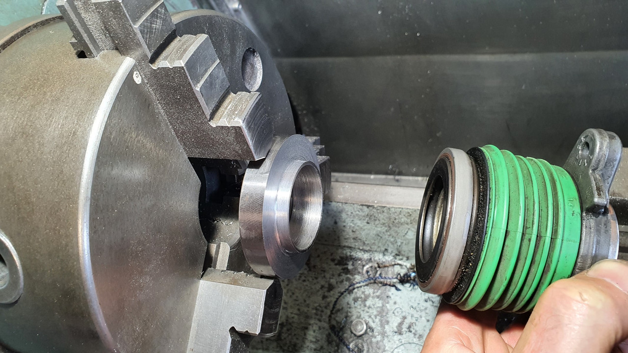
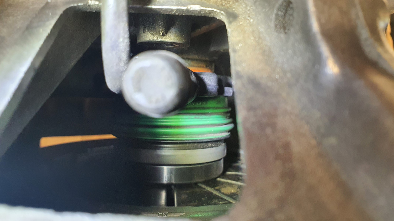
Next issue was fixing this whole unit in place and making sure its dead square to the input shaft centre line. Luckily the units bore was larger that the stub/shaft?* that the Subaru release bearing carrier slides on by about 2mm. It also so happened that when pushed on as far as it would go it allowed for just the right amount of movement of the release bearing, plus a bit to spare.
So I machined a thin sleeve with a lip at one end to suit..
This I made a nice snug fit onto the stub/shaft thing and the Mundano assembly slides in place snug, thus making sure it all remains square.
I assembled the lot together and checked it all with the transmission bolted in place. Looks good..
The initial throw of the release bearing will be adjusted at the pedal, which will now require me to either use the Mundano master cylinder (plastic..yuck) or machine/ sleeve my Imp one (actually the same as a landrover/most trailer brakes out there..) to suit. I'll look at that when I get to it.
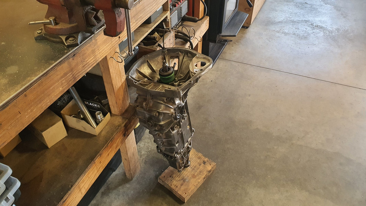
Next step is to bolt the assembly in place. The Leone box has splines cast in around the stub base...
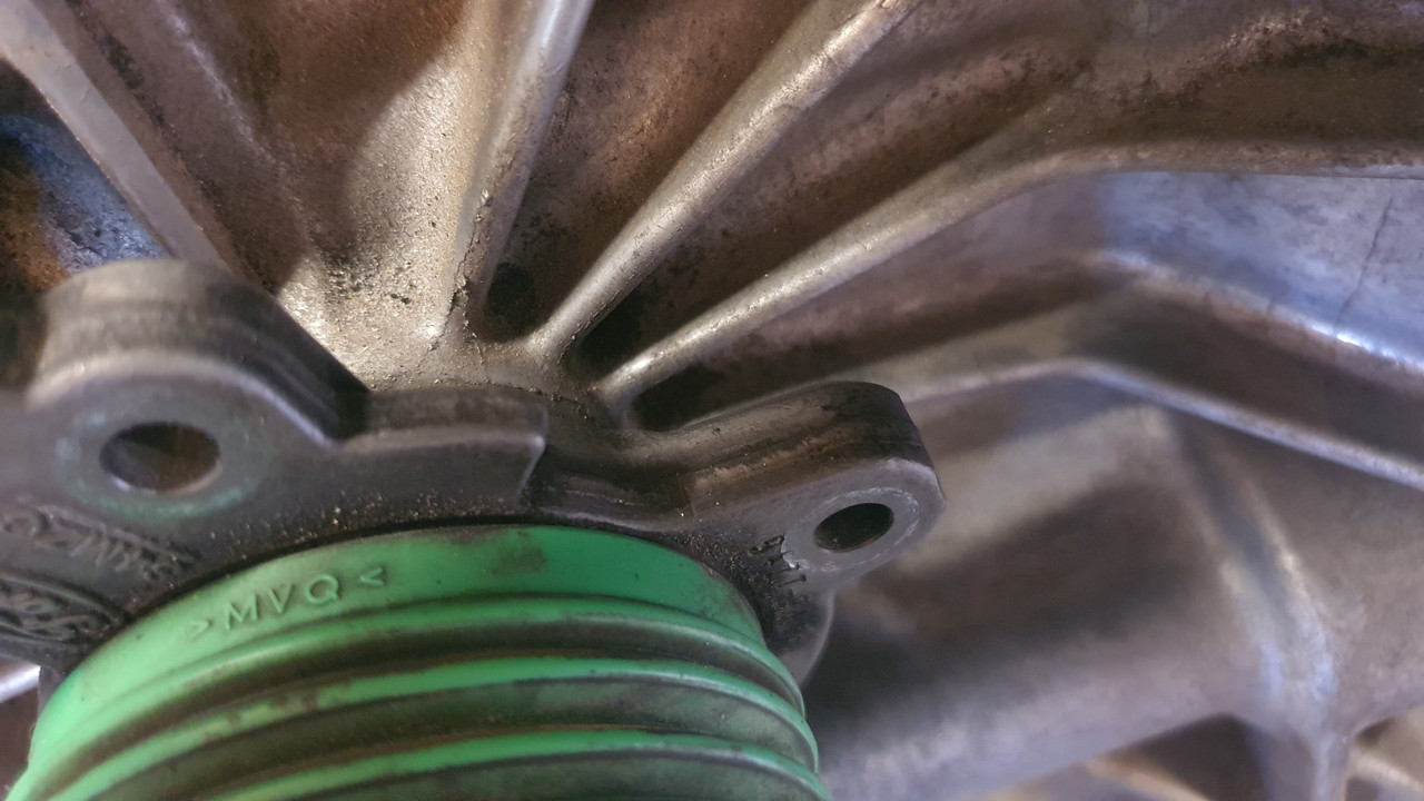
..but luckily enough room between them to glue some blocks in place so I machined some alloy down to suit..
Because I knew the assembly was perfectly straight and in line I just needed to give enough clearance on the blocks to allow for some epoxy. I drilled and tapped the blocks to suit, mixed up some of my favourite JB weld and filled the chosen cavities then slide it back in place. Then let it set overnight..
The next day I tried the original Mundano rubber boot for the pipe exit. It almost fitted. I sliced 5mm out of its width and it was sorted. Not perfect looking but it works and cant be seen once the engine is in place anyway...
Phew. Done. At this point I really did have a feeling like I had made it past the trickiest bits of the engine work required. But for some possible baffles around the oil pump pick up and maybe an anti surge plate (not that the Goldwing engine has any as stock) I think all the required mods to the engine are done. I felt like having a cold beer.
So I did. Then pondered the next jobs to do.
Which was to look at where I would run my cooling pipes and finalise the position of the oil filler tube..
In order to properly work through some routing ideas I had to plonk the heads back on. With them in place I might as well have some fun, bolt the transmission on and stand back with my beer and gaze at it all.
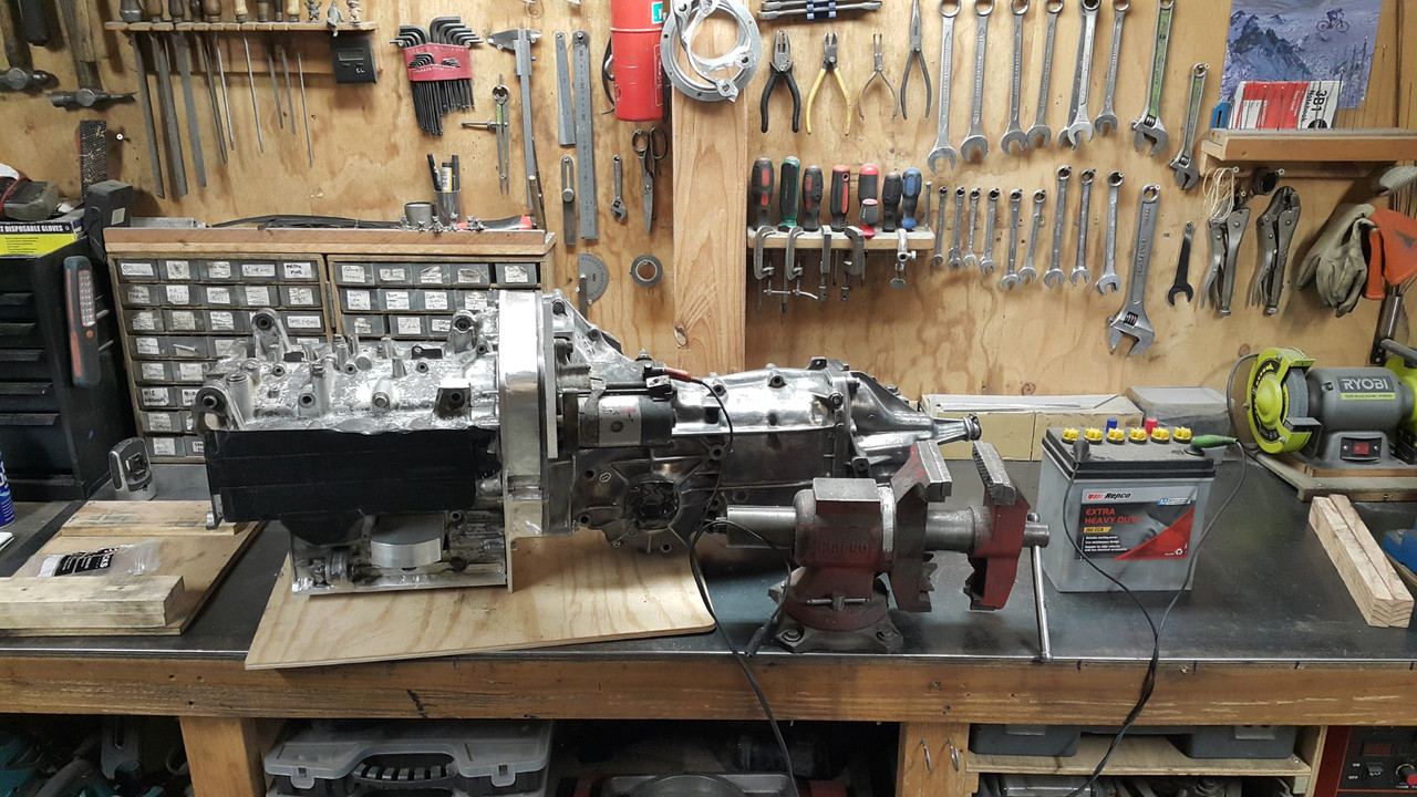
I took some pics. I'm pretty bloody happy with it how it looks and I really did get a mojo boost looking at it sitting there as a complete unit waiting to go in...
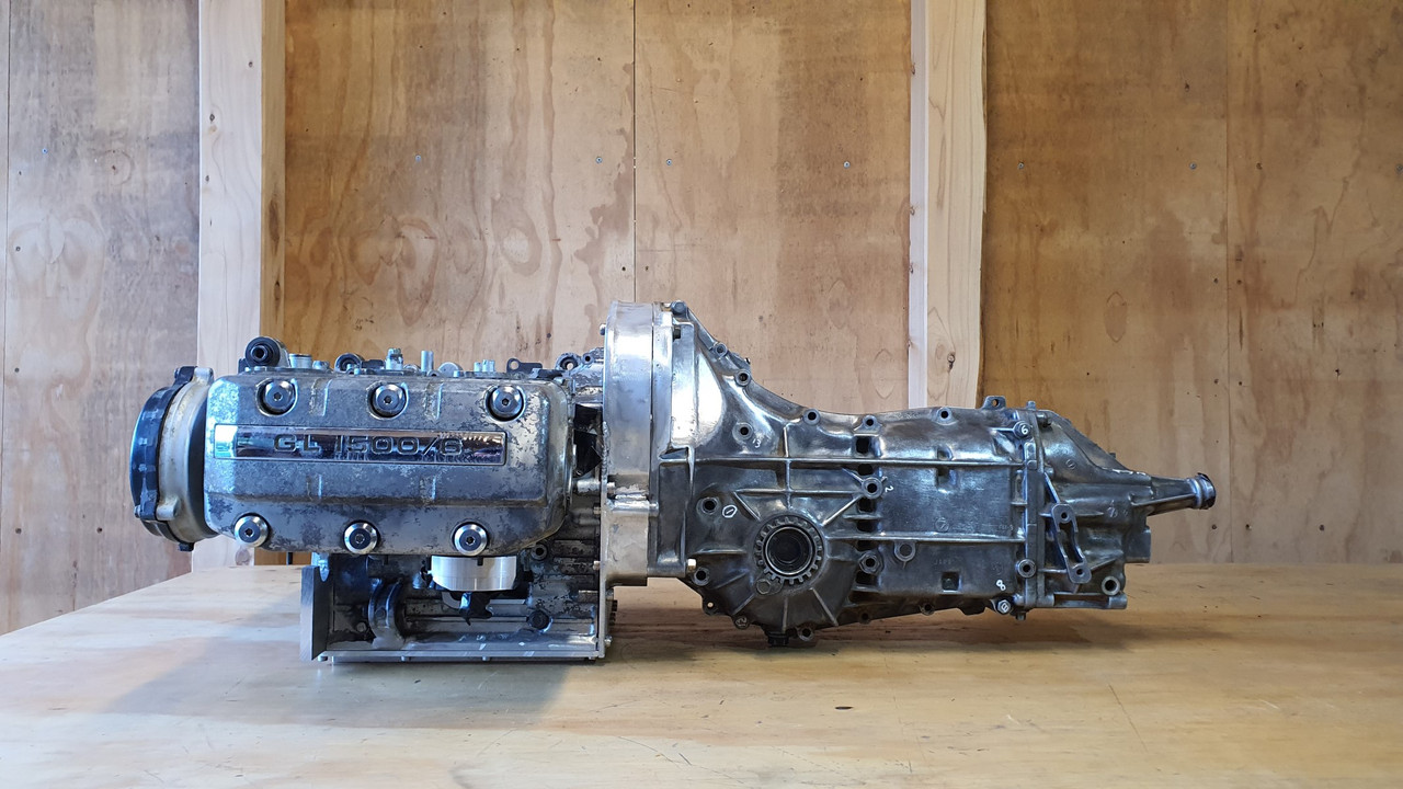
Its so neat and compact for a flat six..
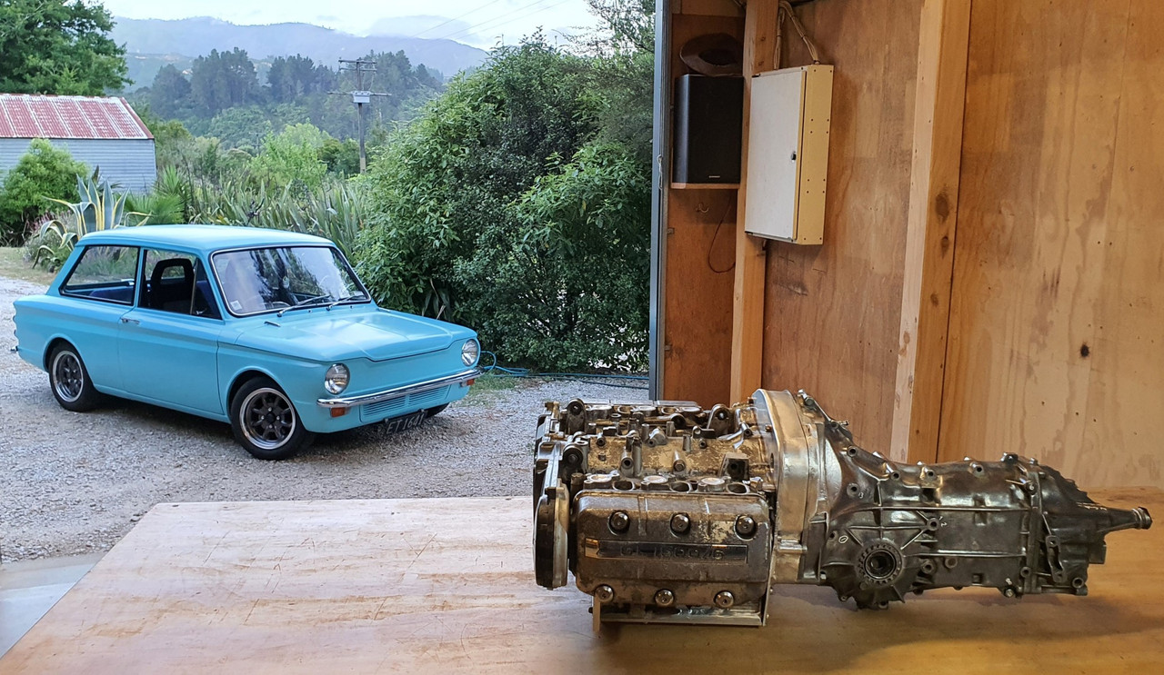
Man I'm looking forward to having this setup in the back of my Imp! What's nice to think about is that while there's still a big load of work to do these next jobs will be super fun. I'm especially looking forward to making the ITB arrangement to suit and doing my best to create a really clean looking engine bay.
Well- I like to think of it as a baby Porsche for the cash poor :-)
Anyway- here's an update...
Next step in the puzzle was to sort out a clutch release system. I had a couple of options that could work. I could use the stock Subaru fork but it was not ideal for two reasons ;
1: It would need a the release bearing carrier adapting to take a larger diameter bearing that would suit the Honda pressure plate fingers.
2: Its pivot location, being a centre mounted fulcrum point, would require a slave cylinder that pushed it towards the front of the car. This is because originally the Leone the transmission came from uses a clutch cable. I'd being using a hydraulic slave and it would have to be mounted up high, over the engine. Probably clash with the underside of the parcel shelf and would definitely look ugly there.
Option two was to use the Ford Mundano concentric slave cylinder I have had stashed away for ages, acquired with the Duratec engine I was going to fit into the Viva wagon many moons ago.
This certainly seemed the most sensible option because it fitted into the location almost perfectly...
The pipes even pop out through the Subaru release fork hole like it was made for it...
But it was still going to require a little work. First off is that it has a flat bearing face, made to suit curved diaphragm spring ends. It was also too small in diameter to suit the fingers.
So a lump of steel was plucked from the store...
There was just enough room between the bearing face and the 'slidey hub' bit that the bearing hydraulics slide in and out on for me to machine a locating stub onto the bit of steel...
With that being a perfect fitting locating point the other side was machined with a radialised face to suit the flat fingers. The end result looks like this..
This will be stuck in place onto the release bearing face with something like loctite 601. It cant go anywhere anyway.
Next issue was fixing this whole unit in place and making sure its dead square to the input shaft centre line. Luckily the units bore was larger that the stub/shaft?* that the Subaru release bearing carrier slides on by about 2mm. It also so happened that when pushed on as far as it would go it allowed for just the right amount of movement of the release bearing, plus a bit to spare.
So I machined a thin sleeve with a lip at one end to suit..
This I made a nice snug fit onto the stub/shaft thing and the Mundano assembly slides in place snug, thus making sure it all remains square.
I assembled the lot together and checked it all with the transmission bolted in place. Looks good..
The initial throw of the release bearing will be adjusted at the pedal, which will now require me to either use the Mundano master cylinder (plastic..yuck) or machine/ sleeve my Imp one (actually the same as a landrover/most trailer brakes out there..) to suit. I'll look at that when I get to it.
Next step is to bolt the assembly in place. The Leone box has splines cast in around the stub base...
..but luckily enough room between them to glue some blocks in place so I machined some alloy down to suit..
Because I knew the assembly was perfectly straight and in line I just needed to give enough clearance on the blocks to allow for some epoxy. I drilled and tapped the blocks to suit, mixed up some of my favourite JB weld and filled the chosen cavities then slide it back in place. Then let it set overnight..
The next day I tried the original Mundano rubber boot for the pipe exit. It almost fitted. I sliced 5mm out of its width and it was sorted. Not perfect looking but it works and cant be seen once the engine is in place anyway...
Phew. Done. At this point I really did have a feeling like I had made it past the trickiest bits of the engine work required. But for some possible baffles around the oil pump pick up and maybe an anti surge plate (not that the Goldwing engine has any as stock) I think all the required mods to the engine are done. I felt like having a cold beer.
So I did. Then pondered the next jobs to do.
Which was to look at where I would run my cooling pipes and finalise the position of the oil filler tube..
In order to properly work through some routing ideas I had to plonk the heads back on. With them in place I might as well have some fun, bolt the transmission on and stand back with my beer and gaze at it all.
I took some pics. I'm pretty bloody happy with it how it looks and I really did get a mojo boost looking at it sitting there as a complete unit waiting to go in...
Its so neat and compact for a flat six..
Man I'm looking forward to having this setup in the back of my Imp! What's nice to think about is that while there's still a big load of work to do these next jobs will be super fun. I'm especially looking forward to making the ITB arrangement to suit and doing my best to create a really clean looking engine bay.
The following users liked this post:
yoeddynz (03-21-2022)
03-21-2022 | 06:10 AM
#30
Thread Starter
Advanced
Joined: Aug 2020
Posts: 73
Likes: 70
From: Motueka, New Zealand
I've still been chipping away at this here and there in between buying K11s and doing work on the property. The first job on it since I last posted was to start sorting out what I was going to build some driveshafts from. I'd picked up two Subaru leone driveshafts from the same fella I'd bought the gearboxes and other bits from.
I also had a large pile of Imp driveshafts. My plan is to join them. Not sure exactly how yet but I'll worry about that later. For now I wanted to clean up and inspect what I have...
.jpg)
.jpg)
These are the bits I'll merge..
.jpg)
Another job done was something a long time waiting. The rear number plate. Its always annoyed me a bit with it positioning down low over the exhaust but that was because it annoyed me even more the way it would obscure the vents on the sports spec engine cover.
Here it is..
.jpg)
So finally I got around to sorting it out. I had @Archetype whip me up one of his wonderful plates but in a smaller size all round..
.jpg)
Nicely made!...
.jpg)
.jpg)
And fitted...
.jpg)
THAT IS WAY BETTER!!!
Next thing was to drag this little thing out of its resting spot near the cabin where its sat for many years now...
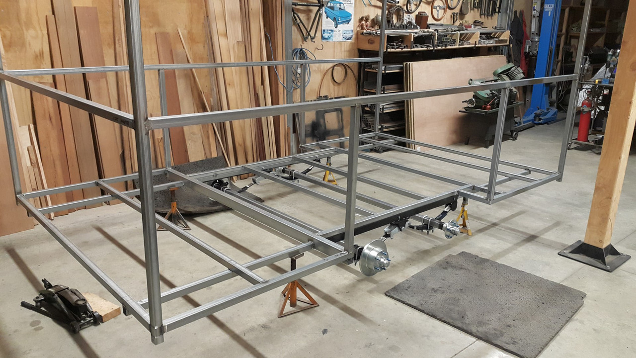
.jpg)
It was sitting right where we wanted to build an extension to this woodshed (woodshed two of four.. cant have too much wood..)
.jpg)
I threw some wheels on it, K11 wheels as you do, then towed it behind big red, our ever useful old Honda quad bike..
.jpg)
Down to the yard and straight into the shed where Impy 2 met Impy 1 again...
.jpg)
I gave Imp 2 a quick clean and removed more flakey rust etc. Quite handy having an old paint job where you can clean the the lichen off with a stainless brillo pad..
.jpg)
.jpg)
As rough as it looks its actually a solid car where it counts and could be rescued. But for now its going to be a jig.
.jpg)
I wanted to set and fix the ride height at where Imp 1 sits. I made some bars that bolted in place of the rear shocks (the fronts I had already done previous to moving it up to the cabin)
.jpg)
.jpg)
.jpg)
These fitted in place meant that the wheels/suspension would not drop when the car was hoisted in the air and so allow me to set now how the transmission outputs would line up with the axles at ride height.
With them sorted the car could go up in the air and I removed the rear arms and crossmember...
.jpg)
It looked horribly rusty and I pictured many hours of swearing at seized bolts...
.jpg)
But actually, possibly thanks to the British engineers designing in leaking seals, the bolts and cross member were covered in oil.
.jpg)
Or maybe a previous owner had done this on purpose. No matter - the bolts all came out really easily.
The cross member removed I discovered that some (Aussie import) Mason wasp had been using the area behind to stash loads of paralysed spiders in little mud crypts, laying an egg within each crypts and when the egg hatches the wasp grub would feast upon the spiders alive.
Nice.
.jpg)
.jpg) \
\
That lot cleaned away. Yuck. Gave the cross member and suspension arms a good wirebrushing and they came up good..
.jpg)
Also cleaned up under the car where I would be working...
.jpg)
I chopped off the end of the driveshafts. Not needed and in the way. i only need the shafts so I can line up the box.
.jpg)
Now it was time to cut out steel and keep cutting until the transmission sat where I had planned it to. First off was to chop out the centre of the cross member. This bolts to a very solid part of the car with many bolts. Once I have finished positioning the engine and box, fabricated the required mounts I'll most likely weld back in a centre section to suit. I'll need to add back in some guide tubes for the handbrake cables etc.
.jpg)
I bolted the box onto the engine and slung it under the car. Lowered the car until it could go no further, marked things and cut steel out. Rinse and repeat until the box sat where it needed to..
.jpg)
Eventually I had the engine sitting pretty much where I wanted it to...
.jpg)
.jpg)
I love the way it sits in so far forwards..
.jpg)
Outputs line up well with the shafts...
.jpg)
Gearbox mounts almost line up. Should not be too hard to make something work within here. Plenty of room. I'll need to get a variety of mounts to try out for size...
.jpg)
Biggest loss in the removal of steel is that the middle of the rear seat base is going to need chopping. Possibly might get away with just removing the springs and what not under the middle but more likely I'll have to convert the base into two separate seats. I'll worry about that later.
.jpg)
.jpg)
Another issue I'll have to sort out is the gearshift. The Subaru box has its gear selector shaft sitting up higher and pointing ever so slightly uphill compared to the stock Imp box. So I'll need to add in a couple of universal joints to link the box to the gearstick. Not a biggy. The rear part of the tunnel will have to rise up from behind the handbrake towards the rear seat base to allow for this. Not like anyone will be sitting there anyway ..
You can sort of make out what I'm talking about here...
.jpg)
So that's where I'm up to as of tonight. I'll get some engine mounts etc and start mounting this lot in place. My plans from here on are to do as much as I can with the car as a jig. Even get the engine running in this car. That way I can keep Imp 1 on the road the whole time.
I also had a large pile of Imp driveshafts. My plan is to join them. Not sure exactly how yet but I'll worry about that later. For now I wanted to clean up and inspect what I have...
These are the bits I'll merge..
Another job done was something a long time waiting. The rear number plate. Its always annoyed me a bit with it positioning down low over the exhaust but that was because it annoyed me even more the way it would obscure the vents on the sports spec engine cover.
Here it is..
So finally I got around to sorting it out. I had @Archetype whip me up one of his wonderful plates but in a smaller size all round..
Nicely made!...
And fitted...
THAT IS WAY BETTER!!!
Next thing was to drag this little thing out of its resting spot near the cabin where its sat for many years now...
It was sitting right where we wanted to build an extension to this woodshed (woodshed two of four.. cant have too much wood..)
I threw some wheels on it, K11 wheels as you do, then towed it behind big red, our ever useful old Honda quad bike..
Down to the yard and straight into the shed where Impy 2 met Impy 1 again...
I gave Imp 2 a quick clean and removed more flakey rust etc. Quite handy having an old paint job where you can clean the the lichen off with a stainless brillo pad..
As rough as it looks its actually a solid car where it counts and could be rescued. But for now its going to be a jig.
I wanted to set and fix the ride height at where Imp 1 sits. I made some bars that bolted in place of the rear shocks (the fronts I had already done previous to moving it up to the cabin)
These fitted in place meant that the wheels/suspension would not drop when the car was hoisted in the air and so allow me to set now how the transmission outputs would line up with the axles at ride height.
With them sorted the car could go up in the air and I removed the rear arms and crossmember...
It looked horribly rusty and I pictured many hours of swearing at seized bolts...
But actually, possibly thanks to the British engineers designing in leaking seals, the bolts and cross member were covered in oil.
Or maybe a previous owner had done this on purpose. No matter - the bolts all came out really easily.
The cross member removed I discovered that some (Aussie import) Mason wasp had been using the area behind to stash loads of paralysed spiders in little mud crypts, laying an egg within each crypts and when the egg hatches the wasp grub would feast upon the spiders alive.
Nice.
\That lot cleaned away. Yuck. Gave the cross member and suspension arms a good wirebrushing and they came up good..
Also cleaned up under the car where I would be working...
I chopped off the end of the driveshafts. Not needed and in the way. i only need the shafts so I can line up the box.
Now it was time to cut out steel and keep cutting until the transmission sat where I had planned it to. First off was to chop out the centre of the cross member. This bolts to a very solid part of the car with many bolts. Once I have finished positioning the engine and box, fabricated the required mounts I'll most likely weld back in a centre section to suit. I'll need to add back in some guide tubes for the handbrake cables etc.
I bolted the box onto the engine and slung it under the car. Lowered the car until it could go no further, marked things and cut steel out. Rinse and repeat until the box sat where it needed to..
Eventually I had the engine sitting pretty much where I wanted it to...
I love the way it sits in so far forwards..
Outputs line up well with the shafts...
Gearbox mounts almost line up. Should not be too hard to make something work within here. Plenty of room. I'll need to get a variety of mounts to try out for size...
Biggest loss in the removal of steel is that the middle of the rear seat base is going to need chopping. Possibly might get away with just removing the springs and what not under the middle but more likely I'll have to convert the base into two separate seats. I'll worry about that later.
Another issue I'll have to sort out is the gearshift. The Subaru box has its gear selector shaft sitting up higher and pointing ever so slightly uphill compared to the stock Imp box. So I'll need to add in a couple of universal joints to link the box to the gearstick. Not a biggy. The rear part of the tunnel will have to rise up from behind the handbrake towards the rear seat base to allow for this. Not like anyone will be sitting there anyway ..
You can sort of make out what I'm talking about here...
So that's where I'm up to as of tonight. I'll get some engine mounts etc and start mounting this lot in place. My plans from here on are to do as much as I can with the car as a jig. Even get the engine running in this car. That way I can keep Imp 1 on the road the whole time.