

1965 Imp 911 - a baby 911 in making....
The following users liked this post:
yoeddynz (01-23-2024)
 01-23-2024 | 01:36 PM
#122
RL Community Team
Rennlist Member
Rennlist Member
Joined: May 2004
Posts: 3,328
Likes: 163
From: Toronto
Wow!
Sounds great! I think you said it all in the first video... "F*** yeah!"
Reading through the whole journey to sort the ICV, hall sensor etc. was very interesting.
Congratulations on such a major milestone!
Sounds great! I think you said it all in the first video... "F*** yeah!"
Reading through the whole journey to sort the ICV, hall sensor etc. was very interesting.
Congratulations on such a major milestone!
The following users liked this post:
yoeddynz (01-23-2024)
The following users liked this post:
yoeddynz (01-29-2024)
01-29-2024 | 04:58 AM
#125
Thread Starter
Advanced
Joined: Aug 2020
Posts: 73
Likes: 70
From: Motueka, New Zealand
It's nice eh. The phone was struggling because so much noise from the cicadas. I have added some temporary silencers and its got a deeper sound now. Vid and another update soon.
01-31-2024 | 03:46 AM
#126
Thread Starter
Advanced
Joined: Aug 2020
Posts: 73
Likes: 70
From: Motueka, New Zealand
Now I had an engine that starts and runs for half a minute I wanted more. I needed a makeshift cooling setup.
I had a spare Nissan March radiator and fan kicking about so that was called into action. I whipped up this beautiful bit of carpentry artwork..
.jpg)
.jpg)
Using a collection of spare hoses I connected the dots between the engine, the electric water pump and the radiator...
.jpg)
I started filling the system with coolant mixed at 35%. Remember this bit. It comes back to haunt me later.
The whole system wouldn't fill up due an airlock in the coolant pipe from the opposite head. There was no way this was going to shift. The standard goldwing cooling system has both top pipes meeting in the middle at a thermostat block so they just bleed the air straight out naturally.
I needed a nipple.
I looked in my collection of various sized nipples and other brake fittings...
.jpg)
Found this small nipple which was perfectly formed and a lovely size...
.jpg)
I needed a boss to inset the nipple into. I machined one up and tig welded it carefully onto the top of the coolant pipe, in a discrete place tucked away behind the alternator so the nipple isn't immediately on display unless you look for it.
.jpg)
Now with the nipple cracked open the large airlock was able leave via some clear vinyl tube. This allowed almost 1.5 litres more coolant in. With the water pump in override mode and twisted sideways I was able to bleed the pump out and the coolant was circulating fine.
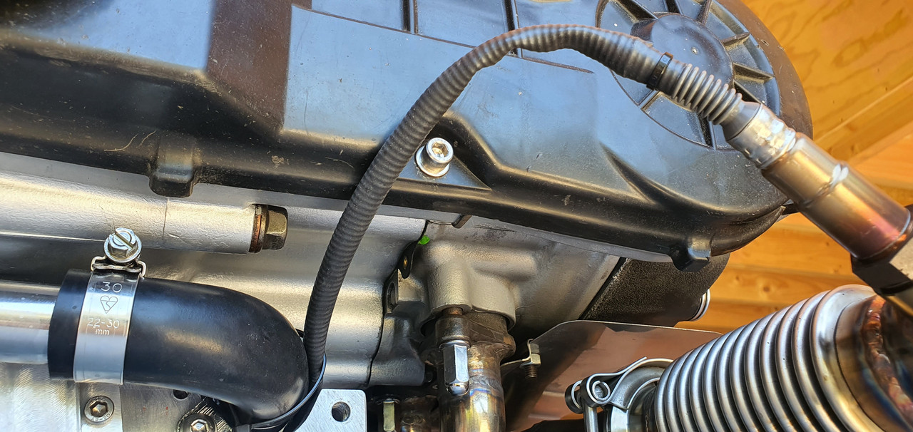
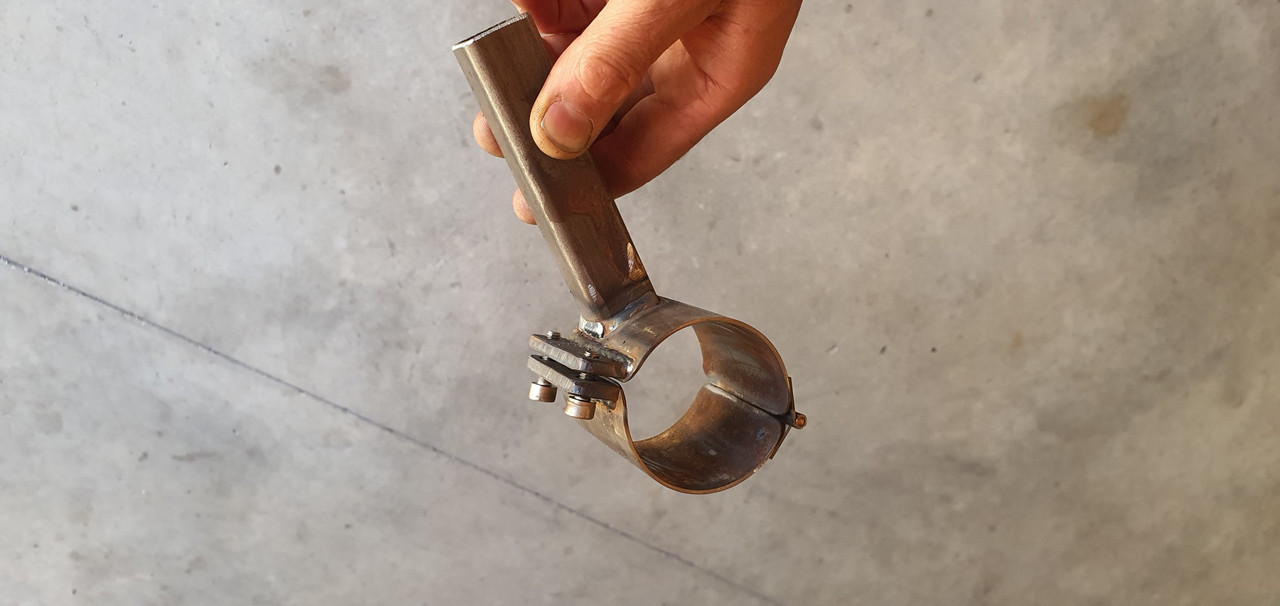
Next step before running the engine for an extended period was to sort out the O2 sensor positioning. Luckily a nice stainless boss from ali land had turned up so that was welded in place ...
.jpg)
I was very happy that I could run the sensor cable around behind the oil filter, completely out of harms way and about as out of view as I could hope for. There's no hiding the ugly sensor sticking out of the exhaust but that's just life.
.jpg)
The exhaust also required a token amount of silencing so I popped the old motorbike silencers outside on the truck deck and painted them with black high temp paint, mainly so I wasn't looking at ugly rusty things..
.jpg)
.jpg)
I also had to do a little bit of extra wiring. The water pump and its controller, the O2 gauge and not to forget the remote unit for the mandalorian spaceship interior lights..
.jpg)
I also wanted to slot my throttle cable adjuster base so I could easily remove the whole cable outer and inner without fuss...
.jpg)
In the mill with a tiny slot drill...
.jpg)
I made a hand throttle using a spare mountain bike brake lever and a bit of suitable alloy tube. But I needed a tiny solderless nipple for the cable end. My tray of bike cable adjusters and such what had nothing small enough so I machined one out of brass and used a 3mm grub screw...
.jpg)
.jpg)
Now I had some basic throttle control without reaching over the engine.
Time to start it up which happened without any fuss. The coolant system worked fine and the engine rose to temp quickly and smoothly. The fan kicks in above my for now setting of 98 degrees. I intended to tune the idle first, once the engine was hot and not using any of the warm up tables etc. But the idle control valve was still passing a touch too much air even when 'closed'. I wound the idle bleed screw in to its stop on the throttle body but still it was idling at 1200 thereabouts. If I blocked the iacv inlet with my finger the revs would drop to circa 700-800. I could also hear a very tiny vac leak from the spaceship window (plenum lid)
Bloody Mandalorians with their terrible glazing skills.
Tightened the lid bolts down and its not bad. Main issue really is the idle valve. I might just make my own like I did with the Mazda V6. Rip the guts out from a stock Mazda item and machine a suitable body to take the solenoid and valve head.
Another issue far more critical that really had me feeling quite low was this...
Coming from here...
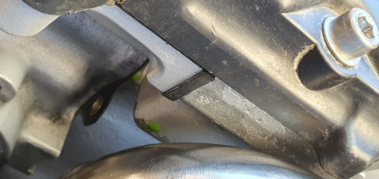
Coolant gallery at base of the head gaskets on each side. It's not dripping but weeping and only once up to temp. I was gutted. I had to travel over to Nelson city that afternoon in my Imp so while there I popped into the engine reconditioners I know there and explained the problem and showed them the photos. Instantly they said I shouldn't have done my first fill with coolant. Apparently it creeps very effectively through any tiny gap before the head gasket has sealed and its slippery/slightly slimy consistency stops the paint on the gasket sticking to the surfaces. All is not lost though. I was instructed to drain the system of coolant, flush everything through thoroughly with clean water and let it dry. I did that last night. I then ran it a couple of times this morning with nothing in it for no more than 30 seconds, allowing it to cool between. Hopefully this will have dried it out and help it seal. Then I was told to just run it with water for a while and see how it goes. It might be ok. If not then they have a kiwi made product called sealwel that many kiwi/aussie reconditioners use with troublesome gaskets. He reckoned its not failed them.
Worst case scenario is a pair of new head gaskets.
and no coolant when setting them !
I might just order the gaskets just in case so I'm not ever in a position where I have to wait later on down the road if the above doesn't work.
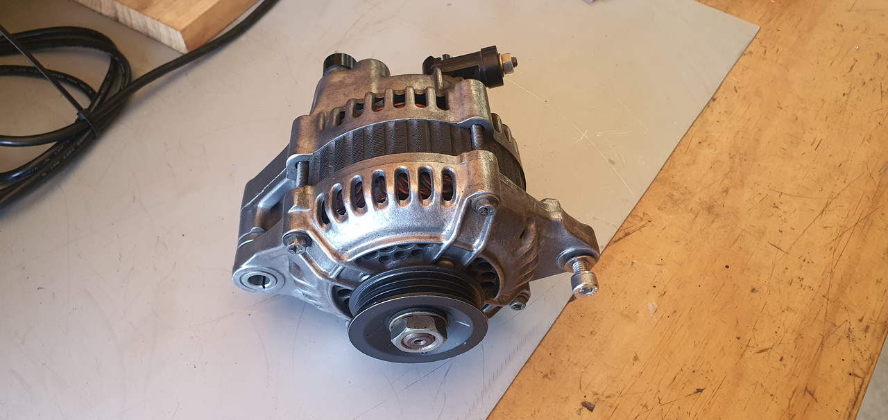
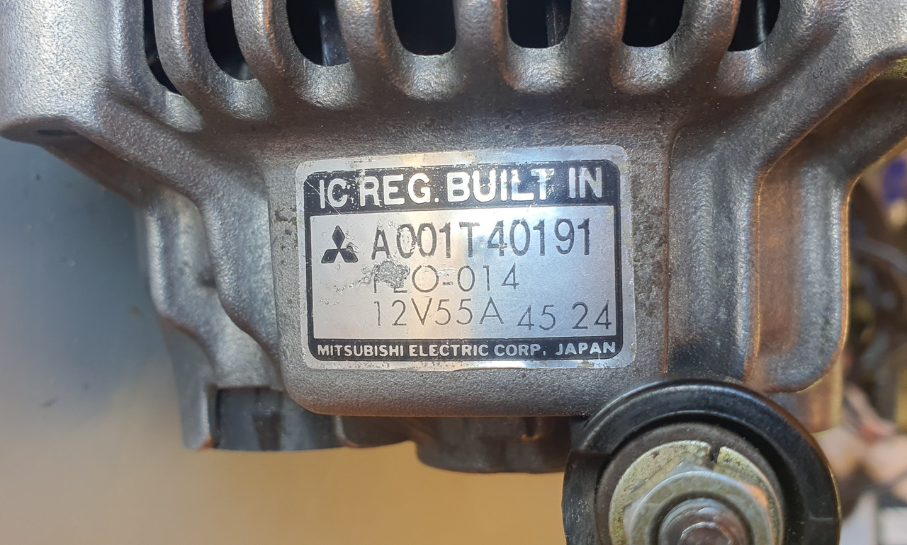
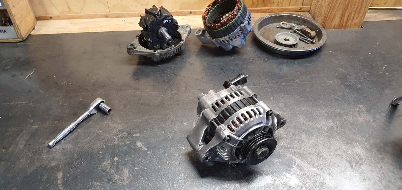
So yeah. I hope its ok and I've plenty of other things to do anyway. Like sort out the alternator that seems to be defective. This one. I need to either fix it or find an exact replacement because the spaceship has been built up to it and there's no room for anything bigger/longer..
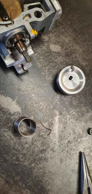
I have also chopped the throttle body spring back a half coil for more tension on the throttle shut. It wasn't closing completely by itself against the strength of the engine want of air.
I had a spare Nissan March radiator and fan kicking about so that was called into action. I whipped up this beautiful bit of carpentry artwork..
Using a collection of spare hoses I connected the dots between the engine, the electric water pump and the radiator...
I started filling the system with coolant mixed at 35%. Remember this bit. It comes back to haunt me later.
The whole system wouldn't fill up due an airlock in the coolant pipe from the opposite head. There was no way this was going to shift. The standard goldwing cooling system has both top pipes meeting in the middle at a thermostat block so they just bleed the air straight out naturally.
I needed a nipple.
I looked in my collection of various sized nipples and other brake fittings...
Found this small nipple which was perfectly formed and a lovely size...
I needed a boss to inset the nipple into. I machined one up and tig welded it carefully onto the top of the coolant pipe, in a discrete place tucked away behind the alternator so the nipple isn't immediately on display unless you look for it.
Now with the nipple cracked open the large airlock was able leave via some clear vinyl tube. This allowed almost 1.5 litres more coolant in. With the water pump in override mode and twisted sideways I was able to bleed the pump out and the coolant was circulating fine.
Next step before running the engine for an extended period was to sort out the O2 sensor positioning. Luckily a nice stainless boss from ali land had turned up so that was welded in place ...
I was very happy that I could run the sensor cable around behind the oil filter, completely out of harms way and about as out of view as I could hope for. There's no hiding the ugly sensor sticking out of the exhaust but that's just life.
The exhaust also required a token amount of silencing so I popped the old motorbike silencers outside on the truck deck and painted them with black high temp paint, mainly so I wasn't looking at ugly rusty things..
I also had to do a little bit of extra wiring. The water pump and its controller, the O2 gauge and not to forget the remote unit for the mandalorian spaceship interior lights..
I also wanted to slot my throttle cable adjuster base so I could easily remove the whole cable outer and inner without fuss...
In the mill with a tiny slot drill...
I made a hand throttle using a spare mountain bike brake lever and a bit of suitable alloy tube. But I needed a tiny solderless nipple for the cable end. My tray of bike cable adjusters and such what had nothing small enough so I machined one out of brass and used a 3mm grub screw...
Now I had some basic throttle control without reaching over the engine.
Time to start it up which happened without any fuss. The coolant system worked fine and the engine rose to temp quickly and smoothly. The fan kicks in above my for now setting of 98 degrees. I intended to tune the idle first, once the engine was hot and not using any of the warm up tables etc. But the idle control valve was still passing a touch too much air even when 'closed'. I wound the idle bleed screw in to its stop on the throttle body but still it was idling at 1200 thereabouts. If I blocked the iacv inlet with my finger the revs would drop to circa 700-800. I could also hear a very tiny vac leak from the spaceship window (plenum lid)
Bloody Mandalorians with their terrible glazing skills.
Tightened the lid bolts down and its not bad. Main issue really is the idle valve. I might just make my own like I did with the Mazda V6. Rip the guts out from a stock Mazda item and machine a suitable body to take the solenoid and valve head.
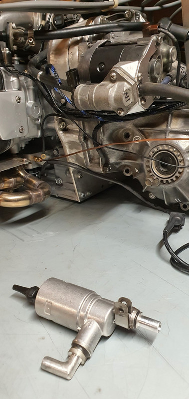
Another issue far more critical that really had me feeling quite low was this...
Coming from here...
Coolant gallery at base of the head gaskets on each side. It's not dripping but weeping and only once up to temp. I was gutted. I had to travel over to Nelson city that afternoon in my Imp so while there I popped into the engine reconditioners I know there and explained the problem and showed them the photos. Instantly they said I shouldn't have done my first fill with coolant. Apparently it creeps very effectively through any tiny gap before the head gasket has sealed and its slippery/slightly slimy consistency stops the paint on the gasket sticking to the surfaces. All is not lost though. I was instructed to drain the system of coolant, flush everything through thoroughly with clean water and let it dry. I did that last night. I then ran it a couple of times this morning with nothing in it for no more than 30 seconds, allowing it to cool between. Hopefully this will have dried it out and help it seal. Then I was told to just run it with water for a while and see how it goes. It might be ok. If not then they have a kiwi made product called sealwel that many kiwi/aussie reconditioners use with troublesome gaskets. He reckoned its not failed them.
Worst case scenario is a pair of new head gaskets.
and no coolant when setting them !
I might just order the gaskets just in case so I'm not ever in a position where I have to wait later on down the road if the above doesn't work.
So yeah. I hope its ok and I've plenty of other things to do anyway. Like sort out the alternator that seems to be defective. This one. I need to either fix it or find an exact replacement because the spaceship has been built up to it and there's no room for anything bigger/longer..
I have also chopped the throttle body spring back a half coil for more tension on the throttle shut. It wasn't closing completely by itself against the strength of the engine want of air.
 02-10-2024 | 05:11 AM
#129
Thread Starter
Advanced
Joined: Aug 2020
Posts: 73
Likes: 70
From: Motueka, New Zealand
I drained all the coolant out, took the radiator and pipework off and flushed the whole lot through until only clean water flowed. Let it sit in the sun while I did other jobs and gave the engine a couple of short 30 second runs to help dry it right out.
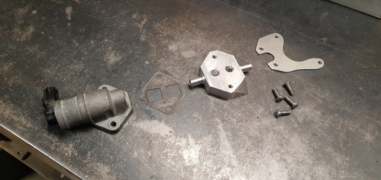
I left it at that and decided to sort out the idle control valve that wont shut completely. I started by removing it and putting it somewhere it'll probably just collect dust for a few months and then maybe get sold/thrown in a bin. I then took Hannah on another exciting date to the local wreckers where we looked under many bonnets to find a suitable replacement.
'Automotive foraging' I like to call it. Here I am in the wilds of the wreckers...
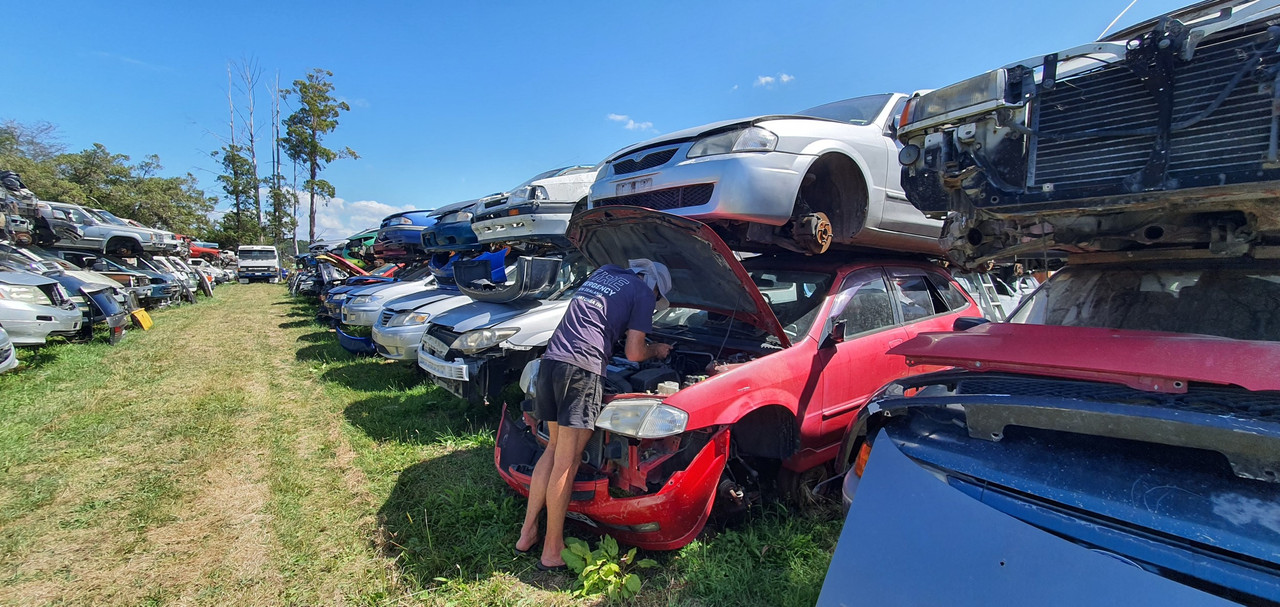
I took home a couple of throttle bodies with valves attached. One from a Mazda 3 and the other from a Mazda 626. They had almost identical iacvs but one had an adjustment. I cut a section of alloy out of a big block..
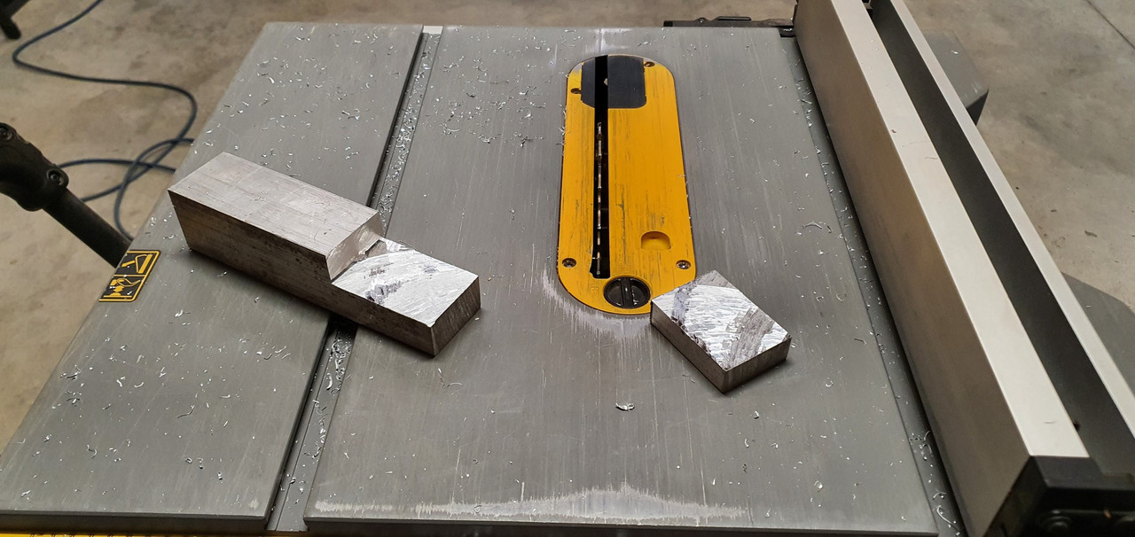
Milled it flat and square..
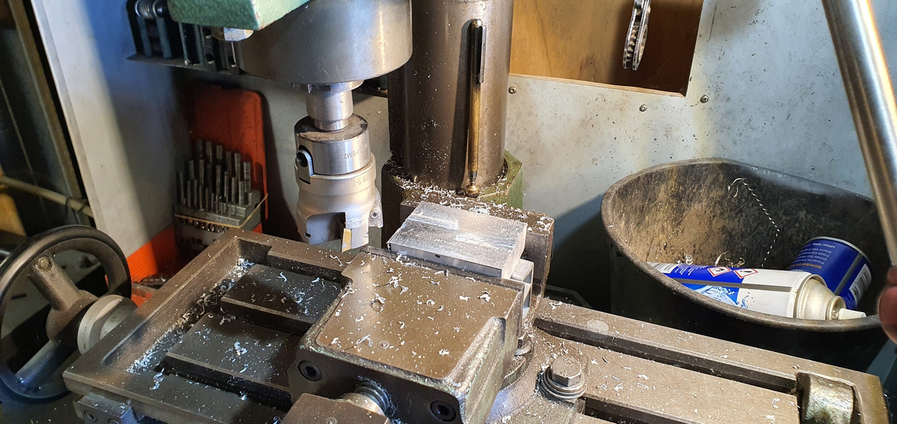
Throttle bodies..
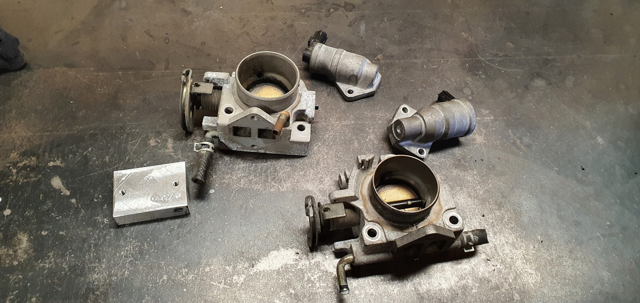
tested them with some pipe and the earlier 626 item has a similar fail safe to my now removed Bosch item, whereby it still lets air through when 'off'.
So that just wont do and I have decided the keeper...
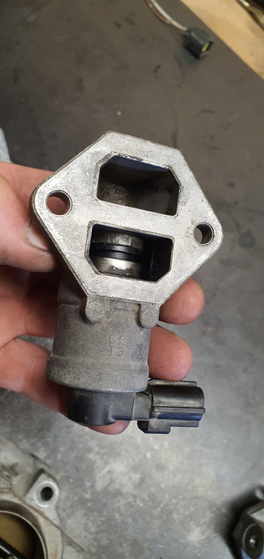
Mazda 3 unit wins this competition and gets to stay in the workshop while the 626 item went in the bin.
I did some more machining of the block so turning it into a ported hub the iacv bolts to, with an in and out pipe pressed in place. I made a bracket to suit the starter motor through bolts to which the aicv block bolts onto. In pictures..
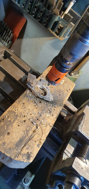
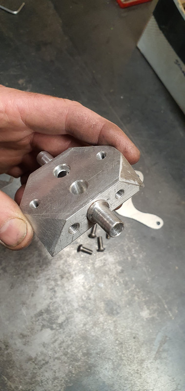
Bolts onto starter like so...
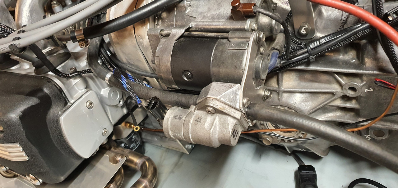
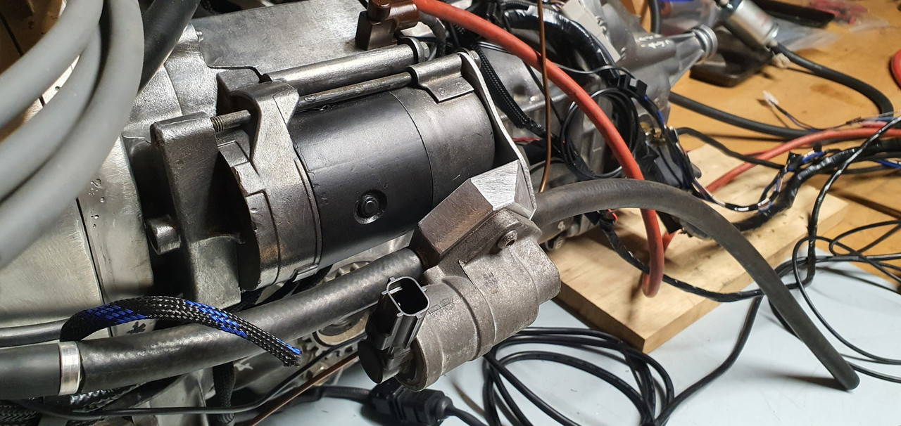
Ended up being not only more compact and better mounted than the old Bosch unit but with better pipe routing too.
I ran the valve through some tests on tuner studio and it works really well, shuts properly and is also much much quieter , partly due to it running at a much higher frequency than the Bosch unit.
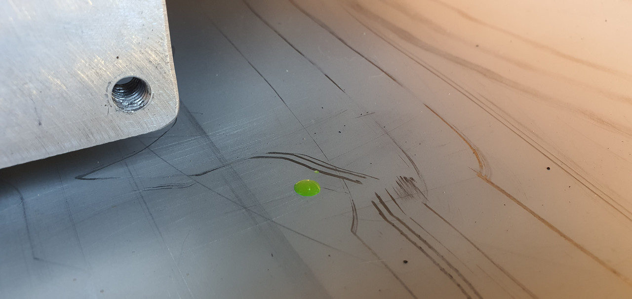
The next thing I thought I'd check was the headbolts out of curiosity to see if they were still torqued up fine. I first laid out some neat material that was absorbent, but waterproof. My sister, a surgery nurse at Wellington hospital, gave it to me and said its handy stuff to have about. Certainly is!...
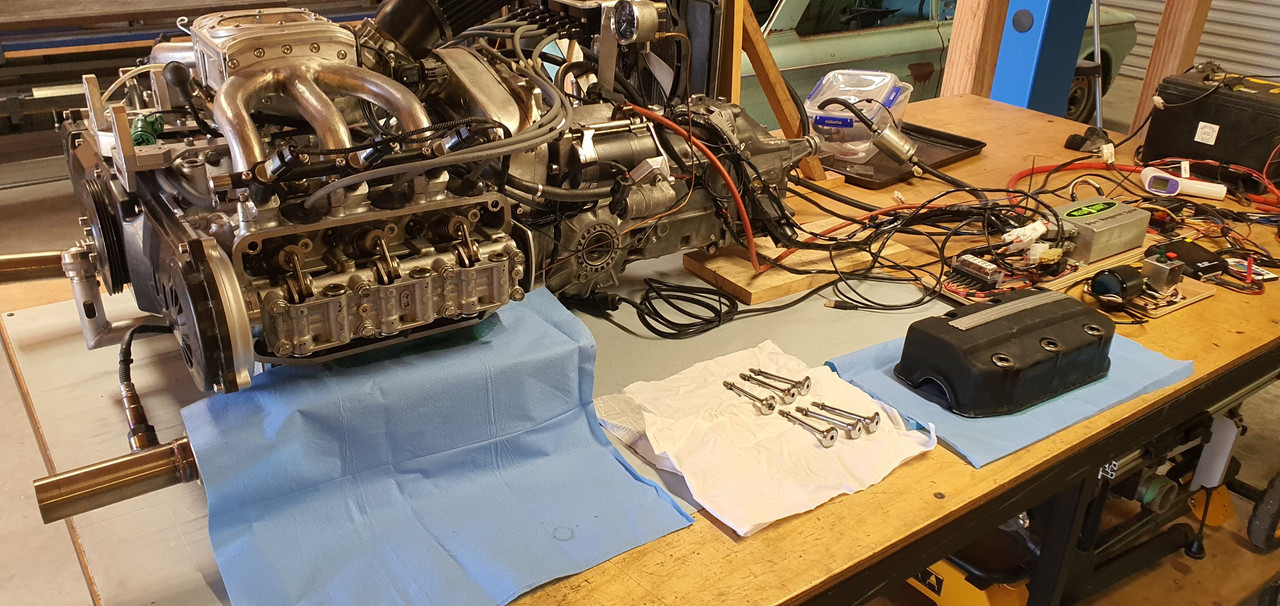
Bolts were all fine and I saw no point in giving them anything extra beyond what Mr Honda specifies, so possibly risking deformation of the heads etc.
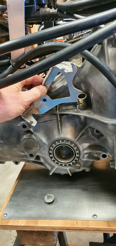
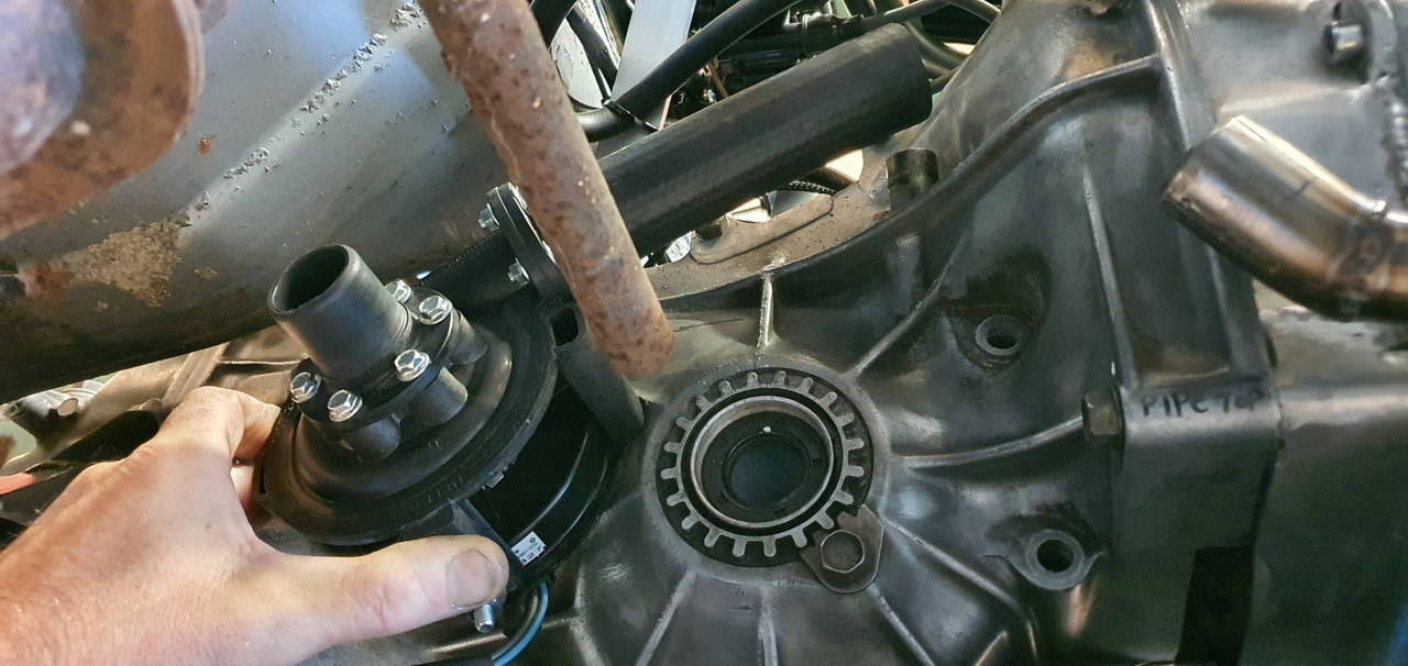
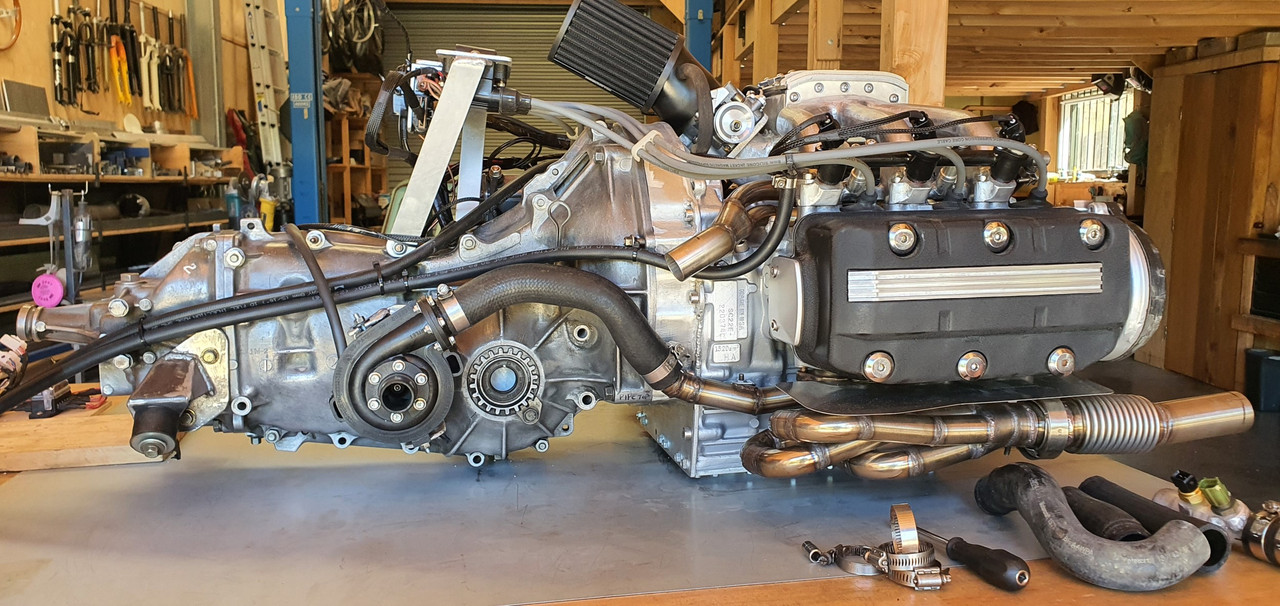
Next thing was to sort out the electric water pump placement. Where I had mounted it turned out to make it a pig to bleed of air due to the outlet pointing downhill and I knew it could be better. See here...
I removed the mounting bracket I'd made for it...
Unplugged the ecu etc etc and slid the whole engine/transmission onto the the 'engine stand 2000'. This process is super easy as it can be adjusted to the same height as the big table or workshop bench and the engine slides really nicely on the ribbed sump.
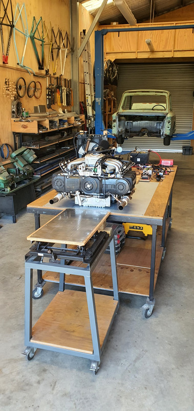
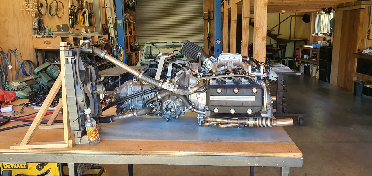
Then I slung it into the spare imp and tried out the water pump for size in the new location I had in mind...
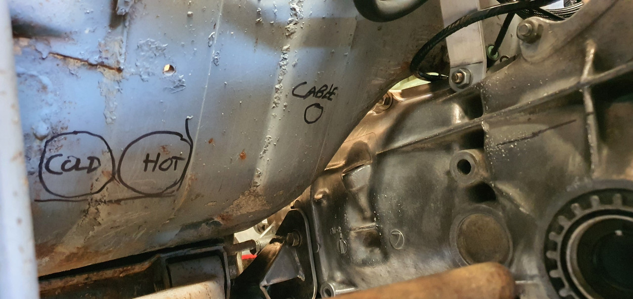
Cooling pipework serving the Datsun engine exit the bodyshell roughly about here...
Much better position. Not only will the pump almost self bleed, being at about the lowest point in the cooling system, but I will also clear up the area of uglyness where it used to be. It also gives me full easy access to the transmission filler/dipstick.
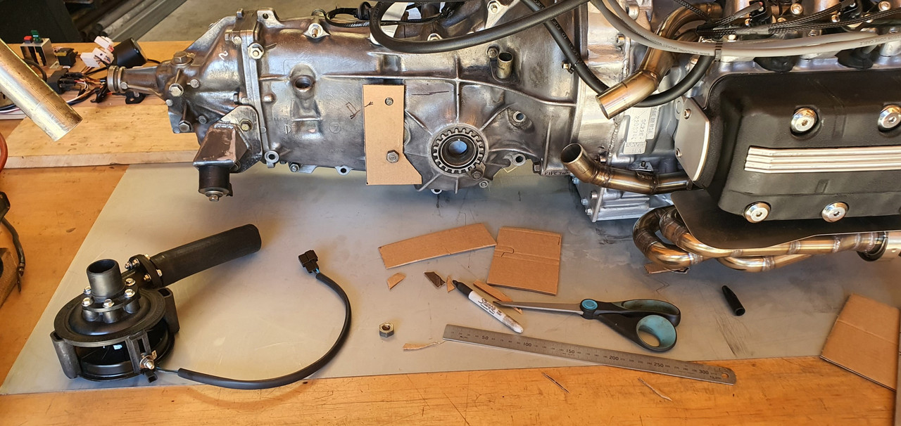
I removed the engine, put it back on the table and set to work marking out for a mounting bracket...
Then fabricated this bracket..
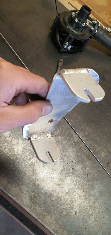
Which mounts the pump here...
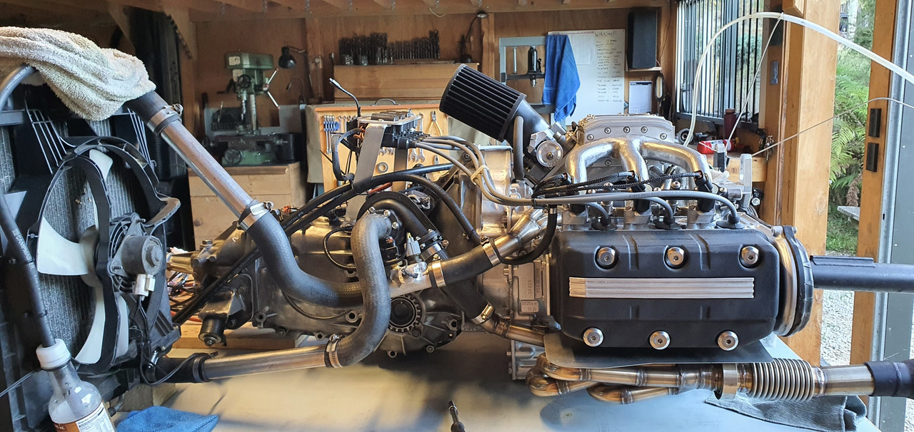
New improved temporary cooling setup which filled up sweet and bleed of air easily..
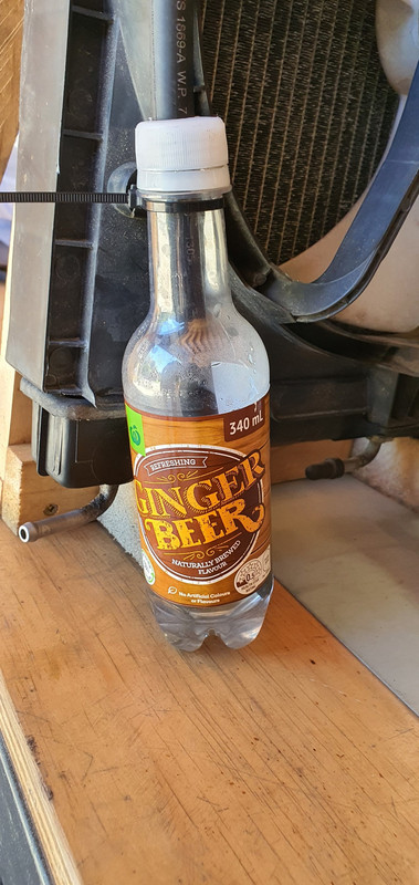
Quality touches..
With the cooling system now filled with just water I ran the engine up to temp. The new iacv was working well and I was more confident in running the engine for as long as my lunchbox fuel can would allow. I kept checking for any leaks and found nothing. The cooling system was working well, the fan kicking on and off, the temp staying around the 95- 97 degrees range I had set on the water pump controller (which also controls the fan relay) and I was finally able to set the idle properly with the idle bleed screw on the throttle body - something I was not able to do with the Bosch iacv which was letting in too much air.
Still no leaks. I ran it several times, let it cool down, checked it the following morning and the level was spot on. Touch wood but I think the extra heat and lack of slippery coolant has allowed the head gaskets to 'set'. Either that or maybe there wasn't a leak at all and it was just residue coolant from spillage when I had removed the top pipes to pressure test them.
Anyway.. I was a farking happy bloke! (Hannah was super happy for me too)
Now with the coolant system working and it idling nicely etc I had the confidence to finally give the engine a decent rev up and see what it sounds like at 6000 rpm. Hannah took a vid...
I just love that sound. The overrun rasp that flat sixes make. It revs up so quick and clean (and there's no acceleration enrichment setup on the tune yet until I sort the main fuel table later on so it can bog if you snap the throttle open too quickly)
Another vid I took showing the hand throttle...
So far the little Mandalorians have managed to keep all their limbs in place. In fact the plenum chamber stays quite cool with the constant stream of cool air flowing into it.
Their spaceship has aircon?
Anyway. I was happy. The only issue was that the whole time I have been running it without any alternator so meaning the ecu is having to use the voltage compensation tables and its not really an ideal situation having everything running at 2-3 volts less than it should.
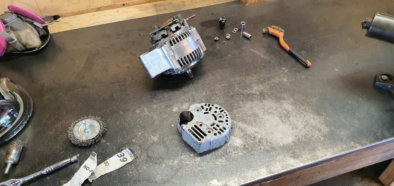
I took my alternator apart again and ran through as many checks I could, following a very handy NZ auto electrical school tutor video about alternator testing online. I suspect the rectifier is kaput and I couldn't locate a cheap replacement.
I managed to locate a second hand alternator, pretty much the same unit and have bought it - now just waiting on the seller to sort their **** out.
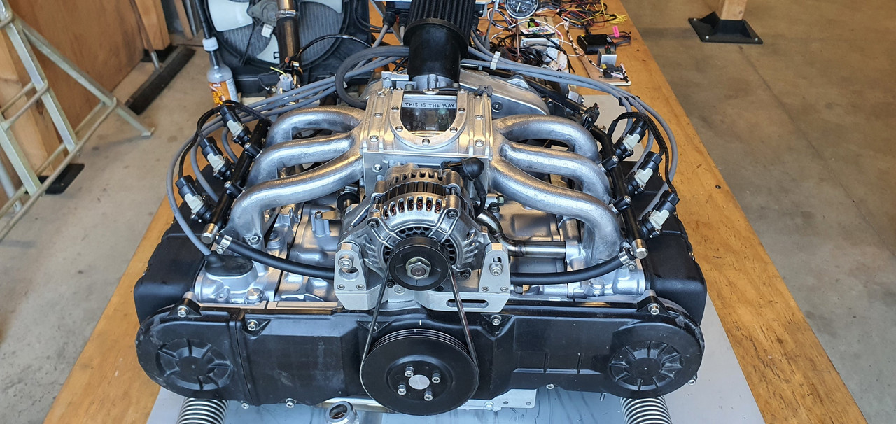
In the meantime I got another similar alternator, this time a nippon denso unit from a Honda prelude that actually has a bit more clearance out back, but with an ugly grey painted steel cover. I ran some pigtail connections and bolted it up, started the engine and now have charging! Yay.

With things running at full voltage I tweaked the engines idle tune and cold start settings and am much happier with where I'm at there.
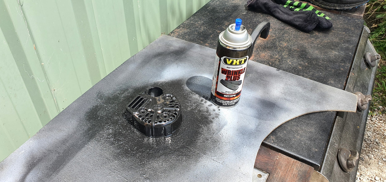
In case the other alternator turns out to not arrive/be a dud etc I decided to give this working unit I do have a bit of a polish and paint. In pics, finishing it off with wrinkle finish paint on the tin end cover.
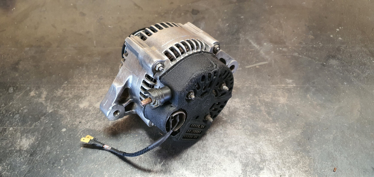
Much better looking. I bolted it back in place and did one final run up to temp with a bit more tuning of the fuel table idle zone. I now have the engine able to idle at 650 and I could almost get a 50cent coin to balance on the plenum lid. The engine is still only sitting on the table, not bolted in place so I cant really expect it to be perfectly smooth. I think it idles a bit nicer at around 750- 800, a zone where its also running leaner at close to 14.7. Lots of time in the future to play with settings.
Confident its all a good starter and idler, plus realising I'm stalling on the next stage, I have now started to take the pump controller, cooling system and temporary wiring apart. The next time it will be started will hopefully be in the Imp. Next job is to reassemble the transmission, bolt the lot into the spare shell and sort out the gear shift linkage.
I left it at that and decided to sort out the idle control valve that wont shut completely. I started by removing it and putting it somewhere it'll probably just collect dust for a few months and then maybe get sold/thrown in a bin. I then took Hannah on another exciting date to the local wreckers where we looked under many bonnets to find a suitable replacement.
'Automotive foraging' I like to call it. Here I am in the wilds of the wreckers...
I took home a couple of throttle bodies with valves attached. One from a Mazda 3 and the other from a Mazda 626. They had almost identical iacvs but one had an adjustment. I cut a section of alloy out of a big block..
Milled it flat and square..
Throttle bodies..
tested them with some pipe and the earlier 626 item has a similar fail safe to my now removed Bosch item, whereby it still lets air through when 'off'.
So that just wont do and I have decided the keeper...
Mazda 3 unit wins this competition and gets to stay in the workshop while the 626 item went in the bin.
I did some more machining of the block so turning it into a ported hub the iacv bolts to, with an in and out pipe pressed in place. I made a bracket to suit the starter motor through bolts to which the aicv block bolts onto. In pictures..
Bolts onto starter like so...
Ended up being not only more compact and better mounted than the old Bosch unit but with better pipe routing too.
I ran the valve through some tests on tuner studio and it works really well, shuts properly and is also much much quieter , partly due to it running at a much higher frequency than the Bosch unit.
The next thing I thought I'd check was the headbolts out of curiosity to see if they were still torqued up fine. I first laid out some neat material that was absorbent, but waterproof. My sister, a surgery nurse at Wellington hospital, gave it to me and said its handy stuff to have about. Certainly is!...
Bolts were all fine and I saw no point in giving them anything extra beyond what Mr Honda specifies, so possibly risking deformation of the heads etc.
Next thing was to sort out the electric water pump placement. Where I had mounted it turned out to make it a pig to bleed of air due to the outlet pointing downhill and I knew it could be better. See here...
I removed the mounting bracket I'd made for it...
Unplugged the ecu etc etc and slid the whole engine/transmission onto the the 'engine stand 2000'. This process is super easy as it can be adjusted to the same height as the big table or workshop bench and the engine slides really nicely on the ribbed sump.
Then I slung it into the spare imp and tried out the water pump for size in the new location I had in mind...
Cooling pipework serving the Datsun engine exit the bodyshell roughly about here...
Much better position. Not only will the pump almost self bleed, being at about the lowest point in the cooling system, but I will also clear up the area of uglyness where it used to be. It also gives me full easy access to the transmission filler/dipstick.
I removed the engine, put it back on the table and set to work marking out for a mounting bracket...
Then fabricated this bracket..
Which mounts the pump here...
New improved temporary cooling setup which filled up sweet and bleed of air easily..
Quality touches..
With the cooling system now filled with just water I ran the engine up to temp. The new iacv was working well and I was more confident in running the engine for as long as my lunchbox fuel can would allow. I kept checking for any leaks and found nothing. The cooling system was working well, the fan kicking on and off, the temp staying around the 95- 97 degrees range I had set on the water pump controller (which also controls the fan relay) and I was finally able to set the idle properly with the idle bleed screw on the throttle body - something I was not able to do with the Bosch iacv which was letting in too much air.
Still no leaks. I ran it several times, let it cool down, checked it the following morning and the level was spot on. Touch wood but I think the extra heat and lack of slippery coolant has allowed the head gaskets to 'set'. Either that or maybe there wasn't a leak at all and it was just residue coolant from spillage when I had removed the top pipes to pressure test them.
Anyway.. I was a farking happy bloke! (Hannah was super happy for me too)
Now with the coolant system working and it idling nicely etc I had the confidence to finally give the engine a decent rev up and see what it sounds like at 6000 rpm. Hannah took a vid...
I just love that sound. The overrun rasp that flat sixes make. It revs up so quick and clean (and there's no acceleration enrichment setup on the tune yet until I sort the main fuel table later on so it can bog if you snap the throttle open too quickly)
Another vid I took showing the hand throttle...
So far the little Mandalorians have managed to keep all their limbs in place. In fact the plenum chamber stays quite cool with the constant stream of cool air flowing into it.
Their spaceship has aircon?
Anyway. I was happy. The only issue was that the whole time I have been running it without any alternator so meaning the ecu is having to use the voltage compensation tables and its not really an ideal situation having everything running at 2-3 volts less than it should.
I took my alternator apart again and ran through as many checks I could, following a very handy NZ auto electrical school tutor video about alternator testing online. I suspect the rectifier is kaput and I couldn't locate a cheap replacement.
I managed to locate a second hand alternator, pretty much the same unit and have bought it - now just waiting on the seller to sort their **** out.
In the meantime I got another similar alternator, this time a nippon denso unit from a Honda prelude that actually has a bit more clearance out back, but with an ugly grey painted steel cover. I ran some pigtail connections and bolted it up, started the engine and now have charging! Yay.
With things running at full voltage I tweaked the engines idle tune and cold start settings and am much happier with where I'm at there.
In case the other alternator turns out to not arrive/be a dud etc I decided to give this working unit I do have a bit of a polish and paint. In pics, finishing it off with wrinkle finish paint on the tin end cover.
Much better looking. I bolted it back in place and did one final run up to temp with a bit more tuning of the fuel table idle zone. I now have the engine able to idle at 650 and I could almost get a 50cent coin to balance on the plenum lid. The engine is still only sitting on the table, not bolted in place so I cant really expect it to be perfectly smooth. I think it idles a bit nicer at around 750- 800, a zone where its also running leaner at close to 14.7. Lots of time in the future to play with settings.
Confident its all a good starter and idler, plus realising I'm stalling on the next stage, I have now started to take the pump controller, cooling system and temporary wiring apart. The next time it will be started will hopefully be in the Imp. Next job is to reassemble the transmission, bolt the lot into the spare shell and sort out the gear shift linkage.
The following users liked this post:
jfischet (02-10-2024)
 02-21-2024 | 05:58 AM
#131
Thread Starter
Advanced
Joined: Aug 2020
Posts: 73
Likes: 70
From: Motueka, New Zealand
Ha. So pretty much the day after I had cleaned up that old alternator up and got it running on the engine the second hand replacement for my original unit turned up in the post.
It came with a 3 month warranty so I'd better check it works before stripping the engine of its ecu etc.
Started to fit it and oh..
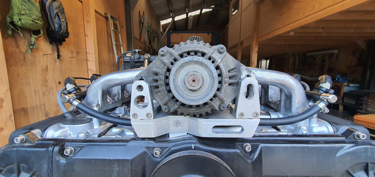
Poos. It wont fit. So I took it apart, along with the original..
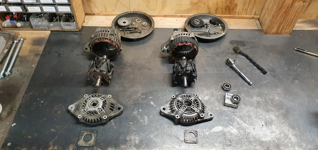
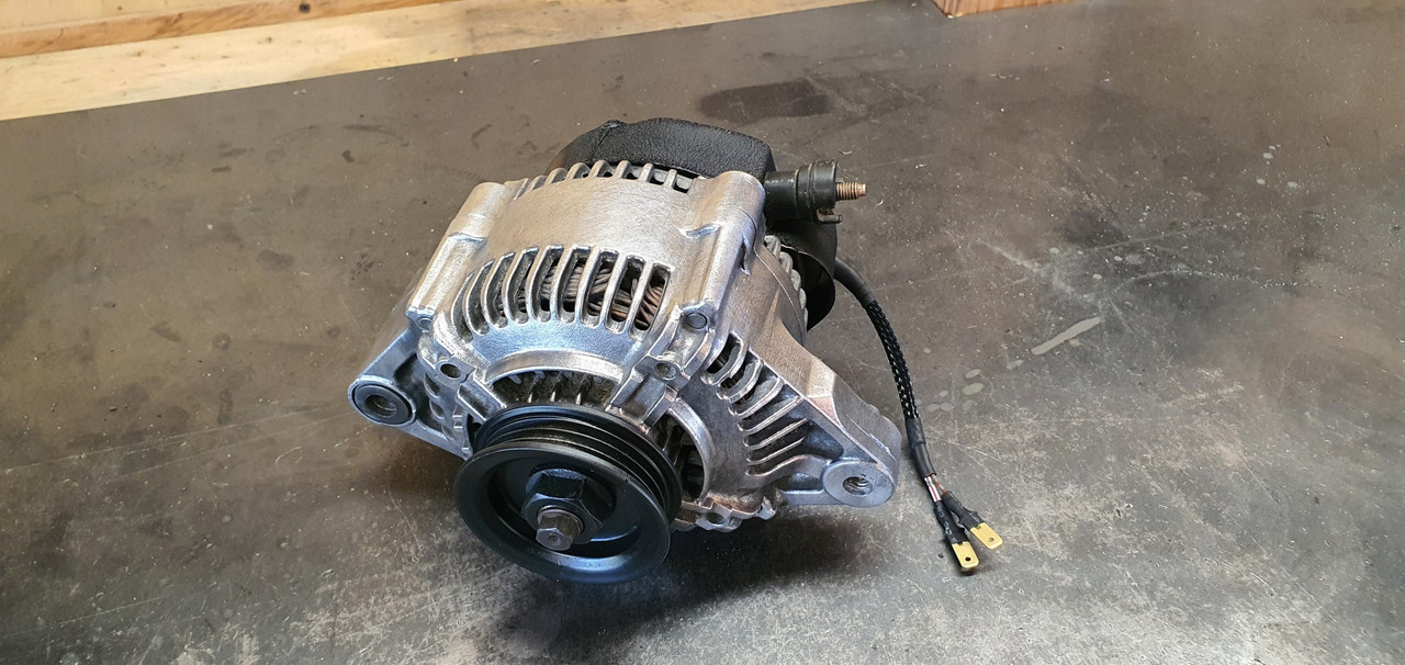
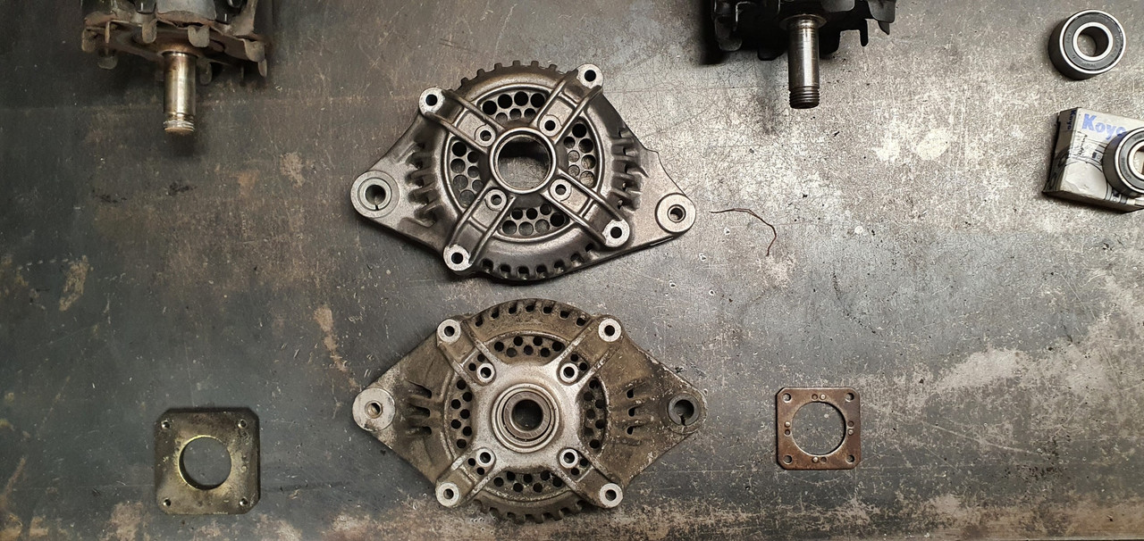
Discovered its just the front housing that's different and I can swap them across..
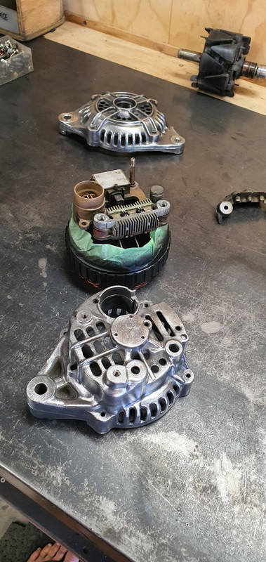
So while its apart it would be rude not to clean all the parts up and polish it all (tempting fate just a bit...)
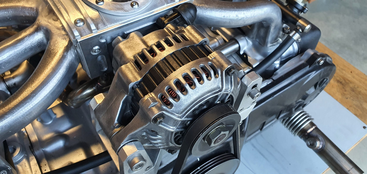
Fitted to the engine and started it up. Yay - it works and it looks great, which is really quite important given its right there, in the middle on display.
I'll keep the other one in storage just in case I need it one day.
Now I could strip the engine back down, removing all the cooling, wiring and fuel lines that I had installed just for bench testing. Then I removed the transmission and put the engine back onto the engine stand 2000, stashing it away because its gearbox tinkering time.
This Leone transmission has a few little issues that need sorting out in order for it to run in reverse rotation and not potentially turn itself into an expensive insinkerator or coffee grinder. I could probably get away without doing these modifications because the box is overbuilt for the application but I wanted peace of mind.
Remember I had acquired the two gearboxes, 1600 and 1800 items, before getting the engine. Ages ago, in fact 4 years ago I think!!! I had wanted to know if it was feasible to run these boxes in reverse. This pic I posted up way back then gives a good idea on what's going on inside...
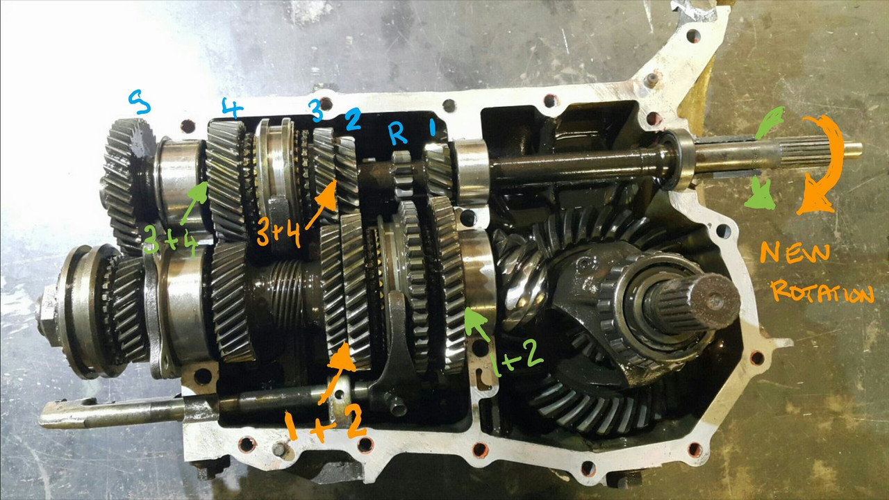
I had already worked out some of the issues back then and knew what I was up for. With more study I found a couple of other areas that need addressing. Here's another bit of wonderful scribbling I did this evening..
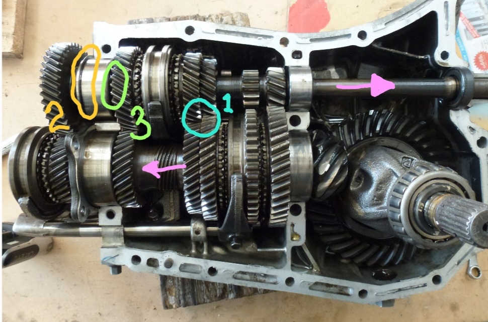
The pink arrows show the new axial forces that are being imparted onto the main (driver) shaft and pinion (driven) shaft. The circles are areas that I think needed attention to make sure it doesn't throw it toys from the cot.
1 : the blue circle. Under high torque loads this area could possibly create the sound of nashing teeth but with much messier consequences. The top left one being the third gear driver wants to move to the right and clip the teeth on the bottom right second gear. In normal rotation they would move apart. There's 1mm of clearance there which is probably enough tbh. But I wanted a bit more and had already worked out how I could get it with no other issues and just a bit of tool making. Which is fun.
2 : The yellow circle. This ring was no going to take thrust loading. It is a strong ring and has a deep groove but I wanted to make sure there was no way it could ever shift.
3 : the green circle. In this area there is a thrust bearing that also acts as a neat little oil pump and squeezes oil through the gear hubs/bushes. Under the new loading the thrust aspect is removed but I still wanted to it pump oil and it was going to be the wrong shape to do so in reverse rotation.
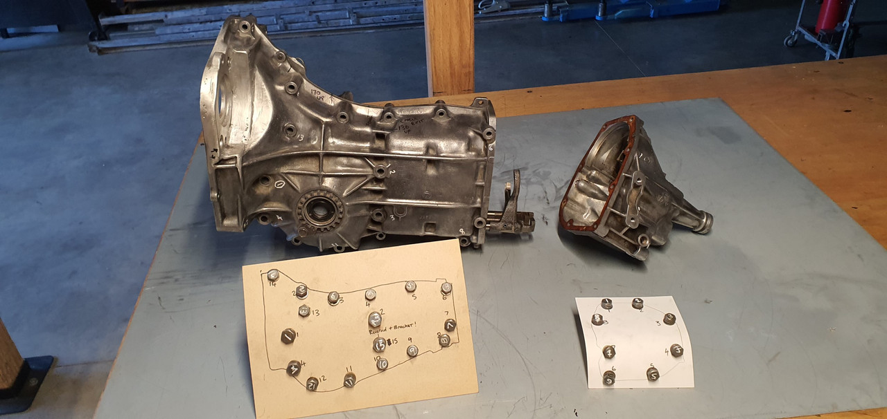
So I set to work and checked off each job. I made a bolt holder for ease of reassembly - several different sizes and lengths.
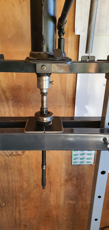
Once apart I started with the gear side clearance. First off I needed to split the mainshaft assembly down. 4 years ago I had out of interest tried using a puller on the spare 1600 box, which shares the same layout and design but with smaller parts in many cases. The puller didn't work. But this time round I have the rather handy workshop press I made. I just needed some extra tooling to do this job. Starting with some press plates...
Allowing me to carefully press the shaft out...
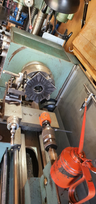
Because I'm not posh (or rich) enough to own a surface grinder I needed to make one. Yes its a bit basic but it will work. I made this...
Which allowed me to do this....
.jpg)
I ended up with this gear having the 0.5mm more clearance I wanted. Super happy with the result.
.jpg)
Now onto number 3 - the little oil pumpy thingee. I went to my friendly engineering workshop in town and got a big lump of 4140 steel. I drilled it out...
.jpg)
Machined out a ring which had to be an exact width. Just in case it needed finishing after the hardening process I made an abor to take it..
.jpg)
I carefully machined it to the right profile, cut the sides down and filed the shapes in, just like the original but in reverse. Happy it was going to work I heat treated it. I have not done any heat treating for over 25 years since I spent a fair bit of time in the blacksmith department while doing my apprenticeship. But it wasn't a super loaded critical component and just had to have a durable hard surface. I didn't take any photos. Hannah was there helping as I carefully heated it up with the oxycet to the austenitic stage and agitated it in some lovely rice bran oil (because I can be posh sometimes) then slapped it in the oven to temper it...
.jpg)
Following morning I polished it. It came up sweet and the old file test showed it to be as hard as the oem item.
.jpg)
You can see the reversed design here...
.jpg)
Here's a little vid I took showing it in action...
While stripping the mainshaft down I was also pleasantly surprised to discover that this 1800 box has needle bearings in all of the gear hubs unlike the 1600 box which uses bushes on the mainshaft. So oil starvation would not have been as much of an issue but I'm still really happy I did this modification.
Last issue to sort was number two - that ring on the bearing. It would hold fine I'm sure but if could make it bulletproof then why not - it's just a bit of extra machining. I started with another lump of high tensile steel and machined out a ring to suit...
.jpg)
.jpg)
This fits over the other ring and then the main thrust plate that sits over the bearing was machined out to suit my reinforcement ring. Its all held in place by the end housing which I have yet to fit.
All the potential issues covered I set to cleaning out the casing and then started reassembly. In doing so I discovered that the original axle seals are sided on these boxes. They have those helical lines on the lip surfaces which aid in pulling/pumping oil back into the oil side of the lip ( the lip does not actually touch the steel when the axle is moving and in fact runs on a tiny bed of oil) which I had not realised before I'd bought plain lip seals from an engineering supplies. This pumping capacity is shown to be twice as high in helixed seals. Subaru fit left and right handed items. But I'm running mine in reverse. Luckily the originals were in excellent condition anyway so I machined up a stepped tool, popped them out and swapped them to the other side.
The diff axle seal surfaces came up good after a clean. Cute little diff..
.jpg)
I'm now about ready to put some 3 bond gloop on the case half and drop the other side in place. Its looking all very nice, clean and shiny in there...
.jpg)
It came with a 3 month warranty so I'd better check it works before stripping the engine of its ecu etc.
Started to fit it and oh..
Poos. It wont fit. So I took it apart, along with the original..
Discovered its just the front housing that's different and I can swap them across..
So while its apart it would be rude not to clean all the parts up and polish it all (tempting fate just a bit...)
Fitted to the engine and started it up. Yay - it works and it looks great, which is really quite important given its right there, in the middle on display.
I'll keep the other one in storage just in case I need it one day.
Now I could strip the engine back down, removing all the cooling, wiring and fuel lines that I had installed just for bench testing. Then I removed the transmission and put the engine back onto the engine stand 2000, stashing it away because its gearbox tinkering time.
This Leone transmission has a few little issues that need sorting out in order for it to run in reverse rotation and not potentially turn itself into an expensive insinkerator or coffee grinder. I could probably get away without doing these modifications because the box is overbuilt for the application but I wanted peace of mind.
Remember I had acquired the two gearboxes, 1600 and 1800 items, before getting the engine. Ages ago, in fact 4 years ago I think!!! I had wanted to know if it was feasible to run these boxes in reverse. This pic I posted up way back then gives a good idea on what's going on inside...
I had already worked out some of the issues back then and knew what I was up for. With more study I found a couple of other areas that need addressing. Here's another bit of wonderful scribbling I did this evening..
The pink arrows show the new axial forces that are being imparted onto the main (driver) shaft and pinion (driven) shaft. The circles are areas that I think needed attention to make sure it doesn't throw it toys from the cot.
1 : the blue circle. Under high torque loads this area could possibly create the sound of nashing teeth but with much messier consequences. The top left one being the third gear driver wants to move to the right and clip the teeth on the bottom right second gear. In normal rotation they would move apart. There's 1mm of clearance there which is probably enough tbh. But I wanted a bit more and had already worked out how I could get it with no other issues and just a bit of tool making. Which is fun.
2 : The yellow circle. This ring was no going to take thrust loading. It is a strong ring and has a deep groove but I wanted to make sure there was no way it could ever shift.
3 : the green circle. In this area there is a thrust bearing that also acts as a neat little oil pump and squeezes oil through the gear hubs/bushes. Under the new loading the thrust aspect is removed but I still wanted to it pump oil and it was going to be the wrong shape to do so in reverse rotation.
So I set to work and checked off each job. I made a bolt holder for ease of reassembly - several different sizes and lengths.
Once apart I started with the gear side clearance. First off I needed to split the mainshaft assembly down. 4 years ago I had out of interest tried using a puller on the spare 1600 box, which shares the same layout and design but with smaller parts in many cases. The puller didn't work. But this time round I have the rather handy workshop press I made. I just needed some extra tooling to do this job. Starting with some press plates...
Allowing me to carefully press the shaft out...
Because I'm not posh (or rich) enough to own a surface grinder I needed to make one. Yes its a bit basic but it will work. I made this...
Which allowed me to do this....
I ended up with this gear having the 0.5mm more clearance I wanted. Super happy with the result.
Now onto number 3 - the little oil pumpy thingee. I went to my friendly engineering workshop in town and got a big lump of 4140 steel. I drilled it out...
Machined out a ring which had to be an exact width. Just in case it needed finishing after the hardening process I made an abor to take it..
I carefully machined it to the right profile, cut the sides down and filed the shapes in, just like the original but in reverse. Happy it was going to work I heat treated it. I have not done any heat treating for over 25 years since I spent a fair bit of time in the blacksmith department while doing my apprenticeship. But it wasn't a super loaded critical component and just had to have a durable hard surface. I didn't take any photos. Hannah was there helping as I carefully heated it up with the oxycet to the austenitic stage and agitated it in some lovely rice bran oil (because I can be posh sometimes) then slapped it in the oven to temper it...
Following morning I polished it. It came up sweet and the old file test showed it to be as hard as the oem item.
You can see the reversed design here...
Here's a little vid I took showing it in action...
While stripping the mainshaft down I was also pleasantly surprised to discover that this 1800 box has needle bearings in all of the gear hubs unlike the 1600 box which uses bushes on the mainshaft. So oil starvation would not have been as much of an issue but I'm still really happy I did this modification.
Last issue to sort was number two - that ring on the bearing. It would hold fine I'm sure but if could make it bulletproof then why not - it's just a bit of extra machining. I started with another lump of high tensile steel and machined out a ring to suit...
This fits over the other ring and then the main thrust plate that sits over the bearing was machined out to suit my reinforcement ring. Its all held in place by the end housing which I have yet to fit.
All the potential issues covered I set to cleaning out the casing and then started reassembly. In doing so I discovered that the original axle seals are sided on these boxes. They have those helical lines on the lip surfaces which aid in pulling/pumping oil back into the oil side of the lip ( the lip does not actually touch the steel when the axle is moving and in fact runs on a tiny bed of oil) which I had not realised before I'd bought plain lip seals from an engineering supplies. This pumping capacity is shown to be twice as high in helixed seals. Subaru fit left and right handed items. But I'm running mine in reverse. Luckily the originals were in excellent condition anyway so I machined up a stepped tool, popped them out and swapped them to the other side.
The diff axle seal surfaces came up good after a clean. Cute little diff..
I'm now about ready to put some 3 bond gloop on the case half and drop the other side in place. Its looking all very nice, clean and shiny in there...
Last edited by yoeddynz; 02-21-2024 at 03:35 PM.
03-17-2024 | 05:30 AM
#132
Thread Starter
Advanced
Joined: Aug 2020
Posts: 73
Likes: 70
From: Motueka, New Zealand
Ok so there's been a couple more big updates on this project. But I have spread myself to thin across the forums and have decided to stop posting it up on each forum. Gets messy and tiring. So please follow this link to my thread on the wonderful low key oldschool.co.nz forum.
https://oldschool.co.nz/index.php?/t...omment-2626866
I'll most likely pop back here when I have the exciting pleasure to post up pics of the cars first drive!
Cheers to those I have entertained here and commented on the thread. I'm having heaps of fun with this build.
Alex
https://oldschool.co.nz/index.php?/t...omment-2626866
I'll most likely pop back here when I have the exciting pleasure to post up pics of the cars first drive!
Cheers to those I have entertained here and commented on the thread. I'm having heaps of fun with this build.
Alex