When you click on links to various merchants on this site and make a purchase, this can result in this site earning a commission. Affiliate programs and affiliations include, but are not limited to, the eBay Partner Network.
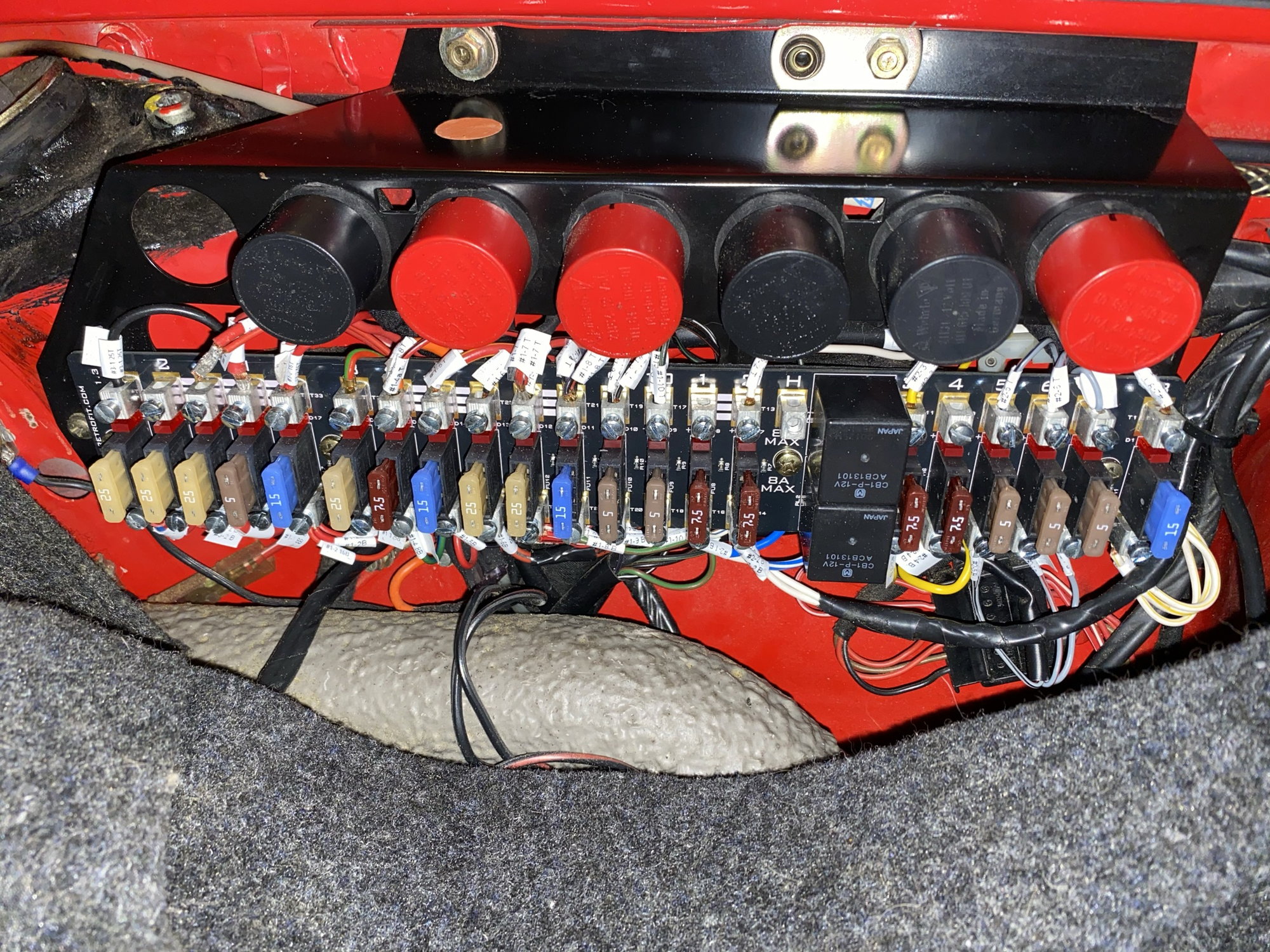
This is for an ‘87 coupe. I have 5 wires, that per the new panel instructions, need to be connected to positions 4 and 5 (from left). The two sets of red wires currently connected in the photo below are in the same position as in the original panel. The unconnected red wire floating just above position 4 came from a connection on the original panel between 4 and 5. There is no such a connection on the new panel and the instructions say to place it in either the position to the left or right (4 or 5 in this case). However, there is no room to fit all these wires in 4 and 5.
On the new panel, positions 2 through 5 are all bridged together as can be seen by the white lines between those connectors. It would seem to me that I could just spread the 5 wires across connections 2 though 5. Is there any reason this cannot be done? Suggestions appreciated. Thanks!
I did this 5 or 6 years ago on my 89 and it was pretty much straight forward ... i bought the conversion kit on Pelican from one of the members
who put it all together , the instructions were clear and simple.
Did you get instructions ?
Perhaps you should post this on Pelican as well !
Do a search , the member was Fred Cook , he sold a lot of his conversion kits
Cheers
Phil
Last edited by wildcat077; 03-11-2021 at 10:39 AM.
Thanks! I added a post on the Pelican forum and also messaged the company. The instructions do not cover this specific scenario. It is just this one problem wire with no home.
Input (line) side of the fuse, right, not the load (fused) side ? Adding to the input side of a bridged set makes no difference which of the bridged terminals you use. Just pick another slot from 2-5 as long they are bridged.
If it's the load (fused) side, you need to do some homework on the circuit.
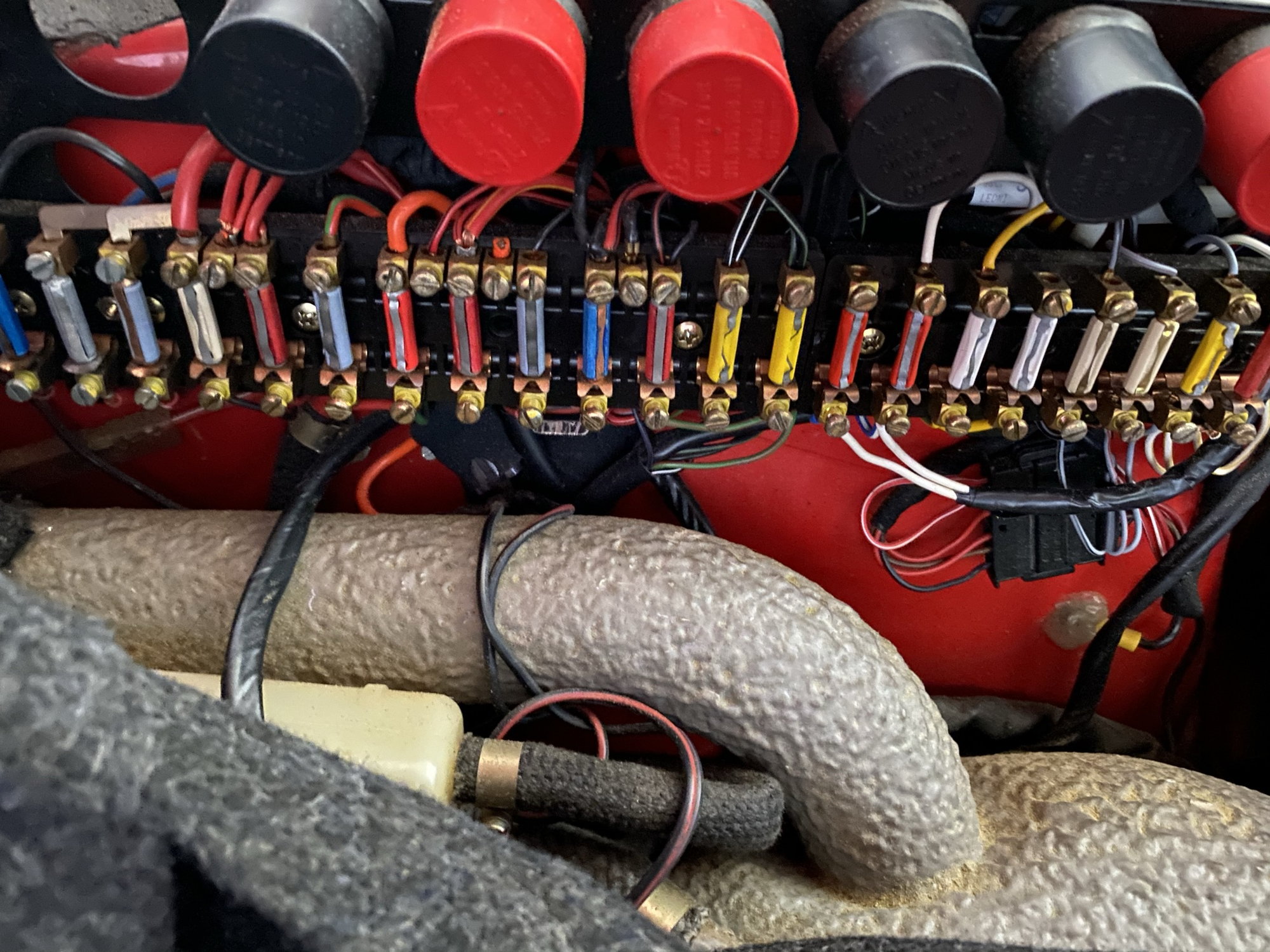
Still a novice in this area. The wire in question to be connected is on the top of the fuse bar, and I would say it is the line side based on my review of the wiring diagrams. The bottom side of the panel seems to be the load side, as per mapping to the diagram wire colors, the wires go to items (loads) such as the radio, hazard light switch, oil cooler fan relay, central locking unit, headlight cleaner CU, ...
Does my interpretation sound correct?
Last edited by ForbiddenRooster; 03-11-2021 at 11:59 AM.
Still a novice in this area. The wire in question to be connected is on the top of the fuse bar, and I would say it is the line side based on my review of the wiring diagrams. The bottom side of the panel seems to be the load side, as per mapping to the diagram wire colors, the wires go to items (loads) such as the radio, hazard light switch, oil cooler fan relay, central locking unit, headlight cleaner CU, ...
While you’re in there , i suggest you de the headlight relay upgrade as well ... think it was J West or something like that ... it could save you
from frying your headlight stalk on the steering wheel !
While you’re in there , i suggest you de the headlight relay upgrade as well ... think it was J West or something like that ... it could save you
from frying your headlight stalk on the steering wheel !
Cheers
Phil
Second this. It is J west. Pelican sells it. Very easy install
While you’re in there , i suggest you de the headlight relay upgrade as well ... think it was J West or something like that ... it could save you
from frying your headlight stalk on the steering wheel !
Cheers
Phil
Headlamp relays are built in to our fuse panel already.
To answer the OPs question, yes the 'extra' wire can be connected to any of the terminals that are 'bussed' together as shown by the white stripes on the fuse panel.
Looks like you had a better experience than I did. Most of my wires on the top end had to be extended as the originals were too short for the new, taller, panel. And a few terminals could not hold all of the wires so there was some splicing involved. As Jonny Retrofit states above, the headlight fuse panel is already in there. Mine took me a solid 12 hours to do all of the wire lengthening...
Looks like you had a better experience than I did. Most of my wires on the top end had to be extended as the originals were too short for the new, taller, panel. And a few terminals could not hold all of the wires so there was some splicing involved. As Jonny Retrofit states above, the headlight fuse panel is already in there. Mine took me a solid 12 hours to do all of the wire lengthening...
The wires can occasionally be shorter due to the handbuilt nature of the cars, but usually the loom can be tugged along a bit from the area near the trunk hinge.
Did your wires have the factory brass ferrules on the end? If not, then may have been cut back.
With thousands of our panels installed, I think your case is the exception rather than the rule.


 03-11-2021 | 09:01 AM